

Abstract
In this paper, we present a novel concept for a planar soft robotic module actuated by smart artificial muscles. The structure consists of a flexible backbone capable of continuously bending along a plane, and having a rigid plate connected to its top. The actuation is provided by an antagonist-agonist pair of artificial muscle fibers, consisting of silicone-based rolled dielectric elastomer actuator (RDEA) membranes connected to the rigid top plate. When actuated via high voltage, the RDEAs expand and, in turn, cause the structure to bend along a desired direction. The novel prototype concept is described in detail first, and systematic parameter studies are conducted afterwards by means of a physics-based model. Then, an experimental prototype is manufactured and tested, with the aim of validating the dependency of the bending angle performance on the system design parameters. We demonstrate that the bending angle is strongly affected by the choice of the flexible beam geometry, as well as the RDEAs mounting points. It is found that, for some combinations of parameters, the buckling instability of the beam can be suitably triggered by the RDEAs, resulting in large bending angles up to 25°. This feature also allows to keep the robot deformed without supplying any electric power. In contrast, parameters corresponding to mono-stable configurations result in a maximum bending angle of 11° only.
Export citation and abstract BibTeX RIS
1. Introduction
Conventional industrial robots, typically consisting of solid metal structures controlled by heavy and bulky drive systems, require special safety measures when employed in human-robot collaboration paradigms [1]. Those measures include sensitive artificial skins, which make use of capacitive sensors to detect humans and obstacles prior to collision [2], or limitations imposed to the maximum payloads and velocity [3]. These solutions, however, result in an unavoidable increase in implementation effort and costs. The field of soft robotics offers an alternative way to address this issue. Thanks to their structural compliance and high flexibility, soft robots allow to intrinsically reduce potential harms to the user [4].
In order to effectively control the large number of degrees of freedom (DoF) of soft robots without affecting their flexibility and compliance, suitable actuator solutions are required. Up to date, the most common driving technologies used in soft robotics are based on pneumatics [5, 6] and motor-driven tendons [7, 8]. Despite effectively providing actuation to the soft robot without affecting its structural stiffness, those solutions rely on bulky and heavy components (e.g. compressors, motors, transmissions) which unavoidably affect the overall system weight, size, and efficiency.
It has been remarked how smart material transducers represent a highly promising alternative for embedding actuation into soft robots [9]. Because of their high flexibility and lightweight, smart materials can be directly integrated within the soft robot structure without requiring additional bulky driving units and mechanical transmissions. Among the many types of smart materials, dielectric elastomers (DEs) appear among the most promising ones for robotic and mechatronic applications [10]. A DE consists of a thin elastomer film (e.g. silicone, acrylic, natural rubber) surrounded by compliant electrodes, which undergoes a surface expansion when subject to high voltage. DEs are often referred to as artificial muscles, because of their large deformation, flexible design, high energy density and efficiency, fast response time, silent operation, and possibility to work as actuators and sensors at the same time (self-sensing) [11–13]. DE actuators (DEAs) can be directly integrated within the structure of a soft robotic system without negatively affecting the overall compliance, weight, and energy efficiency [10]. Several examples of DE soft robot prototypes have been recently proposed in the scientific literature, including soft grippers [14], flexible trunks [15, 16], crawling robots [17], and swimming robots [18, 19]. Most of current works on DE soft robots focus on developing novel concepts to integrate the actuation principle of DEAs within multi-DoF structures. It is worthwhile mentioning that the vast majority of DE soft robot prototypes presented in the literature make use of acrylic material like VHBTM 4910 as elastomer [10, 20]. What makes this material attractive for soft robotic applications is the large strain (up to 400%–500%), together with the relatively low elastic modulus (on the order to 20 kPa [21]). These features allowed researchers to design bending actuators with a deflection angle larger than 90° [22]. Despite their advantages, acrylic DEs suffer from some limitations such as high electro-mechanical losses, high response time, sensitivity to environmental conditions, scarce reliability, and lack of scalable manufacturing process (e.g. for the integration of compliant electrodes) [21, 23]. In contrast, silicone (i.e. polydimethylsiloxane (PDMS))-based DEs are characterized by lower mechanical losses, fast response time (50 times faster [24]) lower leakage conductivity, and longer (>100 times [25]) cyclic lifetime than acrylics, even though they can undergo smaller deformations (on the order of 100% [26]). In addition, scalable and systematic processes have been developed to manufacture compliant electrodes on silicone DE membranes, such as screen printing [27] or spray coating [28]. All those characteristics make silicone a more efficient and reliable material for DE applications [24]. Despite the remarkable advantages of silicone DE, at present there is still a lack of approaches for soft robotic concepts based on this material in the scientific literature. One of the very few examples is the work in [29], in which a silicone-based DE gripper was proposed capable of bending angles up to 60°. In our earlier paper [30], we developed a rotational soft robot concept driven by a double-cone silicone DEA. In this work, the relationship between geometric parameters on the resulting bending angle was systematically investigated, and used to develop design rules which allowed to increase the bending angle almost fivefold, from an initial 2.2° up to 9.6°. From the last example, it is clear how model-based design optimization is essential to exploit the potential of silicone-based DE robotic systems, since it may offer a means to overcome the shortcomings of the material in comparison to acrylic (mostly in terms of strain range) while keeping all its other advantages. Up to date, however, there is a substantial lack of works which perform systematic investigations aimed at developing proper system understanding, design rules for performance scaling, as well as self-sensing based position control architectures for DE soft robots. This is possibly due to the increased level of complexity in comparison to the simpler (and much more understood) case of single-DoF DEAs. Indeed, our previous paper [30] represents one of the first works presenting such type of investigation in the context of DE-based robotic systems. Another crucial aspect for design optimization concerns the use of negative stiffness biasing elements in combination with the DEAs, to increase the achievable motion range. This concept has been extensively used for single-DoF DEA configurations, where a suitable negative stiffness behavior can be implemented based on pre-compressed metal beams [31], or via attracting permanent magnets [32]. Up to date, however, there is still a lack of understanding on how to extend this concept to multi-DoF DE systems such as robots, for which the graphical design methods commonly used in the single-DoF case can no longer be applied.
With the aim of developing and systematically analyzing innovative soft robotic concepts based on DE technology, in this paper we present a novel bendable module driven by silicone-based rolled DE membranes. The first concept of such a system was initially introduced in [33], where only simulation studies were conducted without providing any experimental realization and validation. The system, hereafter referred to as T-platform, consists of a flexible beam capable of bending in-plane, whose tip is connected to a rigid plate. Two pre-tensioned silicone-based rolled DEA (RDEA) elements are mounted on the top plate, acting as an agonist-antagonist pair of artificial muscle fibers [34]. When a RDEA is actuated via high voltage, it expands along its main axis and causes the structure to bend on the opposite direction. Many of those bendable modules can be connected in series, and used to develop a flexible tentacle arm. To begin with, we describe the operating principle of the T-platform, and discuss the most suitable set of parameters which can be studied to optimize its design. Afterwards, we present an extensive model-based parameter study of the T-platform, aimed at understanding how the system free parameters (beam geometry, RDEAs mounting points) affect the resulting bending angle upon electrical actuation. Such a study allows us to determine suitable combinations of design parameters, which are then verified experimentally by means of an extensive characterization campaign. To this end, a novel concept is proposed for the first practical realization and manufacturing of the T-platform prototype. It is found that, for some combinations of design parameters, the buckling instability of the beam can be suitably triggered by the RDEAs, resulting in bending angles up to 25°. This is higher by a factor of 2.5 compared to our previous bendable module concept based on double-cone silicone DEAs [30], for which a maximum bending angle of 9.6° was achieved. Furthermore, compared to the double-cone design in [30], the T-platform is also more suitable for up-scaling and stacking due to its improved aspect ratio. The possibility of exploiting the beam buckling instability to increase the bending angle was initially discovered and analyzed in [35], but the concept was never validated experimentally. The present work represents, to the best of our knowledge, the first experimental validation of a RDEA-driven T-platform, in which a bi-stability-induced magnification of the motion range is demonstrated for the first time in multi-DoF DE soft robots. In addition, this work validates for the first time the ability of the T-platform model initially priposed in [35] to describe a large number of experimental design geometries.
The remainder of this paper is organized as follows. In section 2, the RDEAs are described. The novel T-platform is then discussed in section 3, alongside with a model-based study aimed at understanding how the free design parameters affect the system actuation performance. The T-platform manufacturing process is described in section 4, while the experimental validation of the model-based parameter study is then presented in section 5. Finally, concluding remarks are discussed in section 6.
2. RDEAs
The operating principle of the RDEAs used in this work is briefly summarized in this section. For more details on RDEAs design and manufacturing, the reader may refer to [34].
2.1. Working principle of DEs
The basic structure of a DE corresponds to the one of a parallel-plate capacitor with flexible electrodes and dielectric [36]. By applying high voltage to the electrodes, attractive Coulomb forces are generated between the charges of opposite sign on the two electrodes. As a result, the thickness of the DE decreases and, due to the incompressibility of the elastomer, the membrane surface area increases at the same time. Both thickness reduction and area expansion can be used to generate actuation.
Due to their high flexibility, DEAs can be designed in many different geometries. A popular design is represented by strip-in-plane DEAs (SIP-DEAs) [31]. The basic working principle of this type of actuators is shown in figure 1(a). SIP-DEAs can be used for applications in which a flat layout is preferred, and can also easily stacked on top of each other to increase the resulting work output [37].
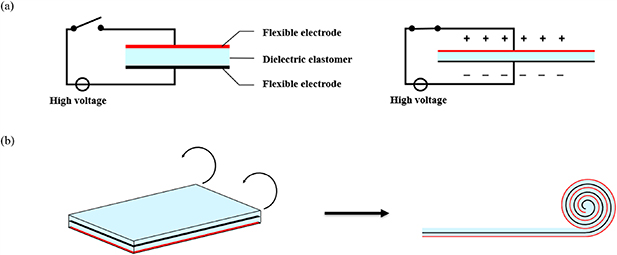
Figure 1. Working principle of DEAs: (a) SIP-DEA, (b) RDEA.
Download figure:
Standard image High-resolution imageIn soft robotics, principles from nature are often taken as a role model. Therefore, a reasonable approach when designing DEAs for soft robotic applications would consist of using biological systems as a guide. As mentioned in the introduction, DEs are often associated to artificial muscles. The structure of human muscles, made of bundles of several fibers, serves as a design template for the RDEA used in this work. Their basic working principle is the same as for SIP-DEAs, but here the dielectric membrane and the electrodes are tightly wound in a cylindrical shape, see figure 1(b). In this case, the high voltage activation produces a reduction in roll diameter and, in turn, an axial expansion. RDEAs can be designed with a very slim aspect ratio (diameter < 4 mm, length > 50 mm), can be easily integrated in soft robotic structures, and can be eventually bundled together to increase the total force [34]. While working as artificial muscle-like actuators, RDEAs can be simultaneously used as nerve-like sensor fibers. In fact, a linear relationship exists between their mechanical deformation and the resulting electrical capacitance [34]. This capacitance-based deformation estimation can be implemented during high voltage actuation, thus realizing the so-called self-sensing operating mode. This unique property is a further advantage of DEs in soft robotic applications, since one does not require additional sensors for controlling the robot in closed loop.
2.2. RDEAs design and manufacturing
The RDEAs considered in this work are manufactured based on the process presented in [34]. Rectangular electrodes (53 mm × 58 mm) with an extension for electrical contact on one side, consisting of carbon black particles suspended in a mixture of PDMS, are screen printed on a 50 μm thin silicone film (Wacker Elastosil 2030). For the considered T-platform application, we restrict our investigation to this single electrode size. In this way, we were able to develop a special manufacturing rig which allows us to systematically manufacture four identical RDEAs at the same time. After screen printing, the films are cured in an oven. The electrodes are then tested with a voltage of 3900 V, to check for defects. If this test is passed, two electrodes with a mirrored layout are cut out and stacked on top of each other. In the subsequent step, the still planar silicone-electrodes sandwich is tightly rolled. To implement the electrical contacts, ferrules are crimped to the ends of the RDEAs and, to simplify the mounting, a nylon rod with a M2 thread is inserted at the free end of each ferrule. In order to supply a high voltage to the actuators, the RDEA ferrules need to be connected to a high voltage amplifier. This is done by screwing a cable shoe with a nut next to the ferrule on the threaded rod. A picture of the final RDEA prototype is shown in figure 2, while its electro-mechanical characterization curves are shown in figure 3 (obtained with the same experimental setup described in [34], in here a small viscoelastic hysteresis can be observed).
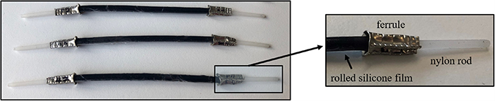
Figure 2. Picture of the manufactured RDEAs.
Download figure:
Standard image High-resolution image
Figure 3. Force-displacement characterization curves of the manufactured RDEAs.
Download figure:
Standard image High-resolution image2.3. Biasing mechanism
In order to achieve a meaningful stroke, a DEA must be pre-tensioned with a suitable biasing system. In the simplest case, the biasing mechanism can be obtained via a constant load (i.e. a mass) or, more commonly, via a linear bias spring (LBS). A simple graphical method, based on a force equilibrium analysis, can be used to predict the stroke of a DEA based on the force-displacement curves of DE membrane and biasing element. An example of application of this method is shown in figure 4(a). In here, the blue and red lines correspond to the DE characteristics for low and high voltage, respectively, while the black line corresponds to the LBS (note that, even though the LBS is a standard Hookean spring, its slope appears negative in this diagram since it is plotted with respect to the DE strain). The intersections between bias and low/high voltage DE curves represent the equilibrium positions when the actuator is turned off and on, respectively. The horizontal distance between these points coincides with the achieved stroke. Given a pair of DE curves, one can freely design the biasing element to tune the stroke accordingly, based on this simple graphical method.

Figure 4. Force equilibrium and graphical design of biasing mechanism: (a) LBS, (b) NBS.
Download figure:
Standard image High-resolution imageHowever, note how the use of simple elements such as masses (constant forces) or LBS results in relatively small strokes (<10% actuation strain), compared to the deformation range achievable by the material. More complex DEA layouts make use of bi-stable biasing elements, such as pre-compressed buckled beam [31], to increase the actuation stroke. The bi-stability of such mechanisms results into a region of negative stiffness (i.e. slope) in their force-displacement characteristics, thus they are commonly referred to as negative bias spring (NBS). If this negative stiffness is properly matched with the positive stiffness of the DEA membrane, a very large stroke (>45% actuation strain) can be achieved, as shown figure 4(b) (also in this case, the negative stiffness of the NBS appears positive in this diagram, since its force is being plotted with respect to the DE strain). It is worthwhile mentioning how, up to date, NBS-based concepts for stroke magnification have only been applied to single-DoF DEA systems, where their design can be effectively performed graphically as described above. The desired stroke and force for the application can be set by adapting the stiffness of the LBS, or in the case of NBS the buckled beam parameters, in such a way that the force-displacement characteristic of the biasing system fits with the desired requirements into the characteristics of the DEs. For more complex DEA systems such as robots, in which several actuators are used at the same time to achieve a multi-DoF behavior, simple one-dimensional graphical methods can no longer be applied for designing the biasing elements. As a result, the high potential of DE material turns out to be highly underutilized in current DE soft robotic applications. A concept for transferring this bi-stability induced stroke magnification to multi-DoF DE systems, and demonstrating it through experiments, represents the main goal of this manuscript.
3. T-platform operating principle and parameter study
After describing the T-platform operating principle, a discussion on the most suitable set of design parameters is presented in this section. Then, a predictive model of the T-platform is summarized and used to perform an initial performance evaluation of the system, in order to guide subsequent experimental investigations.
3.1. Operating principle
A conceptual sketch of the studied T-platform is shown in figure 5. It consists of three main components, i.e. a flexible vertical backbone, a rigid top plate, and the RDEAs, see figure 5(a). As for many soft robotic concepts, the nature is partly used as a role model for the T-platform operating principle. In the human upper arm, flexor and extensor work complementary as an agonist-antagonist pair [38]. In our system, the basic idea consists of using two RDEAs to replicate the role of the agonist-antagonist muscle pair. The RDEAs are mounted in a pretensioned state, with one end connected to the rigid top plate of the backbone while the other end is fixed on the base plate. Figure 5(a) shows the setup in its neutral position. Due to the pretensioning of the RDEAs, a compressive force acts on the top part of the flexible backbone. If a voltage is now applied to one of the actuators, the RDEAs stiffness is reduced and, as a result, the actuator force decreases accordingly. The resulting force imbalance generates a moment, which causes the backbone to bend in-plane towards the opposite direction. The motion obtained when activating the right and left RDEAs is shown in figures 5(b) and (c), respectively. Many of such T-platforms can be eventually stacked on top of each other, resulting into a soft tentacle arm.

Figure 5. Operating principle of the T-platform: (a) neutral position, (b) bending when the right RDEA is actuated, (c) bending when the left RDEA is actuated.
Download figure:
Standard image High-resolution imageOne of the advantages of the proposed T-platform is represented by the possibility of exploiting the beam as a bi-stable biasing element for stroke magnification. In fact, by properly tuning the RDEAs pretensioning, the normal force acting on the beam can be made slightly larger than the buckling load. In this state, the force change due to the electrical activation of a RDEA is sufficiently large to trigger the beam buckling instability, thus causing it to snap and, in turn, produce a large bending displacement. For a detailed theoretical analysis of this phenomenon, the reader may refer to [35]. By exploiting this effect, it is possible to generalize the bi-stability induced stroke magnification concept, extensively used in case of simple DEAs [31], to the considered class of multi-DoF DE robotic structure. In this way, the actuation performance can be dramatically increased given the same amount of active material and input voltage.
3.2. Determination of the free design parameters
The T-platform is characterized by several free design parameters, which strongly affect its displacement performance. Those include the geometry of both beam and rigid plate, as well as the size and attachment points of the RDEAs. Not only those parameters are critical for determining whether the bi-stable actuation can be made possible, but can be also used to further fine-tune the resulting displacement range. A systematic understanding of the relationship between free parameters and resulting motion range is essential for the design of high-performance DE soft robotic systems. Since the system is characterized by a large number of design parameters, it is inconvenient to attempt optimizing all of them at the same time. In here, we will discuss a suitable subset of free design parameters for practical design optimization, whose effects on the T-platform performance will be investigated in subsequent sections.
The first and most relevant parameters are represented by the ones related to the RDEAs geometry. In fact, the shape of the RDEA force-displacement characteristics strongly depend on their geometry as well as their manufacturing process [34]. Since the relationship between RDEA geometry and their force-displacement behavior was already investigated in [34], it will not be further studied in this work. Conversely, for design convenience, we will focus on a specific actuator geometry that can be manufactured in a highly reliable way (see section 2.2).
In addition to the RDEAs, the flexible backbone also plays a fundamental role in determining the system bending angle. The most important parameter describing the backbone flexibility, namely the bending stiffness, strongly depends on the chosen material and beam geometry [35]. A rectangular shape is considered for the cross section, to allow exploiting known results from classic beam theory for quantitative performance predictions. This results in four main free parameters for beam, namely cross-sectional thickness, cross-sectional width, length, and material (i.e. Young's modulus). Since all those parameters affect the beam bending stiffness in a lumped way, it is sufficient to change only one of them for our study. For practical design reasons, we decided to only investigate the effects of the beam thickness on the overall bending stiffness, leaving its other geometric parameters (length, width) and beam material constant.
Further free parameters result from the assembly of the various components. The attachment points of the RDEAs on the top and bottom plates strongly affect the direction along which the actuation forces are transmitted to the flexible structure, as well as the RDEA pre-stretch. Therefore, it is expected that such points have a meaningful impact on the bending performance. Since the structure needs to be symmetrical, the two attachment points on the left- and right-hand sides are selected in an equal manner. The horizontal distances from the attachment points of the RDEAs with respect to the beam top and bottom points are then chosen as further main parameters to investigate. The vertical positions of the RDEA attachment points, as well as the beam length and width, are fixed in a heuristic way compatibly with the size of the actuators discussed in section 2.2, in order to ensure a RDEA strain of about 50% in the initial vertical position (since higher values might damage the RDEAs).
To conclude this section, we report in figure 6 a summary of all the free quantities considered for the parameter study.
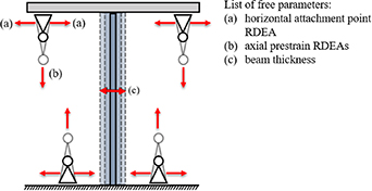
Figure 6. Free design parameters of the T-platform.
Download figure:
Standard image High-resolution image3.3. Model-based parameter study
In order to obtain a preliminary assessment of the effects of the free design parameters (i.e. upper and lower attachment points, beam thickness) on the bending performance of the T-platform, a model-based study is conducted in this section. This model allows us to establish a framework for the basic design and understanding of the bendable module and its associated theoretical performance. In this way, suitable parameter ranges can be evaluated for the subsequent experimental testing campaign.
As a first step, we summarize a physics-based, quasi-static model of the considered soft robotic system. The result is grounded on the energy-based modeling framework we previously developed for the T-platform in [35], which is here updated with our most recent version of the RDEA model [39] as well as with a novel kinematic description which accounts for the actual structure of the novel experimental setup. Figures 7(a) and (b) depict a schematic representation, the T-platform in both undeformed and deformed configurations, respectively. In here, all the relevant system component and geometric parameters are also highlighted. The model essentially comprises three main elements of the T-platform, namely the rigid top plate, the flexible beam, and the RDEAs. For simplicity, we assume that the geometric state of the beam and RDEAs is uniquely determined once the configuration of the top plate is fixed (see [35] for details). For a planar motion, this allows us to completely describe the system with the following vector of generalized coordinates
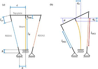
Figure 7. Sketch of the T-platform kinematic model, (a) undeformed configuration, (b) deformed configuration.
Download figure:
Standard image High-resolution imagewhose components correspond to the horizontal and vertical displacement of the beam tip, as well as the orientation of the top plate, respectively (cf figure 7(b)). According to Lagrangian mechanics, the system equilibrium configurations are given by the solutions of the following system of equations
where ν is the total potential energy of the system. In our case, ν can be expressed as the sum of three sub-components, i.e.

representing the gravitational potential energy of the top plate, the elastic potential energy of the beam, and the electro-mechanical potential co-energy of the RDEAs, respectively. νTP and νB can be expressed as a function of q as follows [35]

where
mTP is the rigid top platform mass, g is the gravitational constant, lB is the undeformed beam length, EB is the Young's modulus of the beam material, IB is the beam second moment of area, and AB is the beam cross-sectional area. By assuming a beam with a rectangular cross-section with width wB and thickness tB, we can simply compute the last two beam parameters as IB = wB tB 3/12 and AB = wB tB. In order to define the DE electro-mechanical energy, we first need to define two additional quantities, i.e. the vector of DE voltages vDE
as well as the vector of DE lengths lDE (cf figure 7(b))
where subscript i refers to RDEA i, i = 1, 2, lcr takes into account the length of the passive crimps connecting the RDEAs to the T-platform pivot points, and all the other geometric parameters are reported in figure 7. Then, based on (6), (7), the total co-energy of the RDEAs can be expressed as follows [35, 39]
where L1, L2, L3 are the RDEAs principal lengths in undeformed configuration, Cj 0 are Yeoh parameters describing the DE material hyperelastic response, j = 1, 2, 3, αe 1 an ηb are volumetric loss factors of the RDEA, ε0 is the vacuum permittivity, and εr is the DE relative permittivity. The complete set of equations describing the T-platform steady-state response can be obtained by replacing (4), (5), (7), (8) in (3) (explicit computations are straightforward but cumbersome, thus they are omitted here for conciseness). In this way, we can compute the system equilibrium configurations resulting from the application of a given pair of input DE voltages.
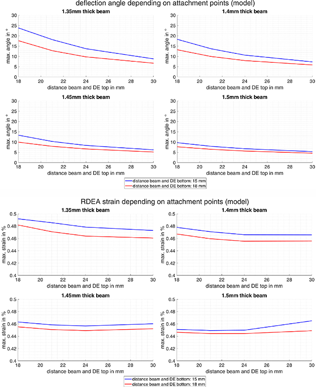
Figure 8. Model-based parameter study, T-platform bending angle (upper part) and maximum RDEA strain (lower part).
Download figure:
Standard image High-resolution imageThe developed model is then used to perform some initial parameter studies, aimed at understanding the trends of how the bending angle α varies as a function of the free design parameters shown in figure 6, i.e. upper RDEA attachment point c, lower RDEA attachment point a, beam thickness tB. All the other model parameters are assumed to be known in advance. In particular, the beam length and width, as well as the constant geometric parameters of the structure, are fixed in a heuristic according to the guidelines provided at the end of section 3.2. The DE material parameters are obtained based on the RDEA characterization in figure 3, while the beam Young's modulus and the top-plate mass are determined based on known properties of available 3D printing materials (i.e. PETG [40], Rigid 10 K Resin [41], see section 4 for more details). The numerical values used for all the constant parameters are summarized
As a final remark, we include some considerations on the maximum electric field, which is related to electrical breakdown in the DE. The electric field of RDEA i, i = 1, 2, is given by [39]
For the maximum DE length obtained in simulation, a peak electric field of about 73.5 V μm−1 is computed. Since this is always smaller than the safety value of 80 V μm−1 recommended by the elastomer manufacturer, we can consider the system suitable from an electrical viewpoint.
4. T-platform manufacturing and assembly
In order to experimentally validate the performance predicted by the model-based study, the overall T-platform design must guarantee the possibility of varying the parameters of interest independently of each other, within their ideal range of variation determined in section 3.3. A suitable physical realization for such a design is discussed in this section.
To ensure consistency with the theoretical T-platform concept in figure 5, the connection between actuators and platform should allow the RDEAs to spontaneously orient itself along the line passing through the top and bottom attachment points. Furthermore, the horizontal distance between the center of the platform and the attachment points should be freely variable, and the vertical position of the attachment point should be precisely adjustable as well. The free alignment is ensured by an adapter mounted on the threaded rod of the RDEAs, which has a triangular profile on both sides. This profile is hooked into a larger triangular notch in the rigid platform, as shown in figure 9. The adapter is held in place by the tensile force of the RDEA, which presses it against a nut serving as a mechanical stop. Due to the size difference between the triangular notch and the adapter, the profile can rotate freely in the notch, and thus it can always adjust its direction according to the one of the RDEA force. The horizontal distance to the platform center can be varied by placing several notches at different distances from the central axis of the beam, see figure 9. The nut, which serves as stop for the attachment adapter, can be used at the same time to finely adjust the vertical position. Six notches are provided on the top plate, equally spaced with an offset of 3 mm. Therefore, the attachment point of the RDEAs can be varied from 18 mm to 30 mm with steps of 3 mm. Two notches are provided onto the lower platform, placed at a distance of 15 mm and 18 mm, respectively.

Figure 9. Structure for RDEA attachment and tuneable mounting point on the T-platform.
Download figure:
Standard image High-resolution imageFor connecting the flexible beam to the base and top plates, a screw-based clamping device is incorporated into the design of both plates. The beam is simply inserted into a gap on the two plates, so that it can be manually replaced in a simple way. To allow accurate insertion of beams with different thickness at the center of the gap, 3D printed rubber plates are used as adapters. In the last step, the beam is fixed with two screws on each side.
Figure 10(a) shows the CAD model of the final T-platform. The rigid top plate and the bottom plate are printed with a SLA 3D printer. The SLA printer ensures an accurate resolution of the notches. Due to their fine profile structure, the adapters for RDEA attachment are also fabricated with the same printer. A bottom plate filament, printed out of PETG, is used to rigidly connect the T-platform to the test bench. Once in this configuration, the RDEAs and the backbone can be mounted between the two plates. For the backbone fabrication, a selection of different PETG beams are printed with the filament printer, according to the geometry provided in the
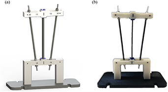
Figure 10. Assembled T-platform: (a) CAD model, (b) first experimental prototype.
Download figure:
Standard image High-resolution image5. Experimental results
This section presents an experimental characterization of the T-platform, together with an experimental validation of the parameter study.
5.1. Experimental test rig
A custom test rig is assembled to systematically characterize the T-platform, and evaluate the performance achieved with different design parameters. For each combination of parameters, an experiment is conducted in which different periodic voltage signals are alternately applied to the left and right RDEA. Two high voltage amplifiers available in our lab (Hivolt HA51U, Ultravolt 4HVA) are used for this purpose, both of them compatible with the voltage/capacitance range of the RDEAs. During this process, a camera is used to record the motion of the module. The test rig allows to automatically detect the position of the T-platform, track its motion over time, and compute the resulting bending angle.
To make the setup as independent as possible from focus settings and camera position, those parameters should be automatically recognizable by (and account for) the motion tracking algorithm. To this end, the MATLAB 'Camera Calibrator' app is used to extract those parameters through at least two reference coordinate systems located in different planes. In order to recognize the coordinate systems during the video post-processing, three tilted plates with a chessboard pattern are placed in the test rig. Note that two of the chessboard plates are out of plane with the T-platform and one plate in plane with the T-platform. By means of an image recognition algorithm, it is possible to identify the individual corners of the chessboard, and use them to generate a coherent coordinate system. The two out of plane coordinate systems are used in the calibration app to get the camera settings. And the third one as reference coordinate system for the T-platform. The complete arrangement of T-platform and three chessboard plates is portrayed in figure 11(a).
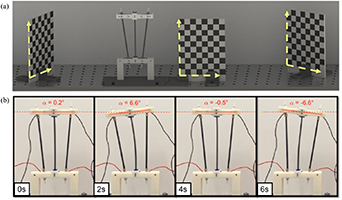
Figure 11. Experimental setup for characterization of the T-platform: (a) test rig with reference coordinate systems, (b) deflection angle tracking in video.
Download figure:
Standard image High-resolution imageTo further assist the motion tracking algorithm, three markers are placed on both the base and the top plate of the T-platform (i.e. two black dots and a vertical line for each element), also visible in figure 10. The marked positions on the T-platform can now be determined with respect to the reference coordinate systems. Once the positions of all the T-platform relevant points are obtained, their motion can be tracked in the video. In the last step, the bending angle can be computed from the positions of the moving points by using standard rigid body kinematics. The result of this tracking algorithm for the angle of deflection is shown in figure 11(b).
5.2. T-platform actuation performance and parameter study
The developed test rig can be used to determine the relationship between the bending angle and the various parameters discussed in section 3. Other than just analyzing the angular displacement performance, it is also meaningful to investigate for which combinations of parameters the system is bi-stable, and how the bi-stability feature affects the maximum deflection angle. The performance of different prototypes are measured, by considering all the possible combinations of the following parameters (for a total of 32 experiments):
- Top DE distance c: 18 mm, 21, mm, 24 mm, 30 mm;
- Bottom DE distance a: 15 mm, 18 mm;
- Beam thickness tB: 1.35 mm, 1.4 mm, 1.45 mm, 1.5 mm.
Note that the configurations corresponding to c = 27 mm are omitted, since they led to almost identical performance compared to the 30 mm case.
During the measurements, a square wave voltage signal with a duration of 2 s and a constant amplitude of 3000 V is applied alternately to the two actuators, in such a way that both rolls remain inactive for 4 s between activations. An example of such a signal is shown in figure 12.
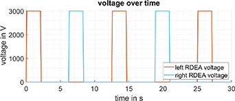
Figure 12. Applied voltage signal to the actuators for experimental investigation.
Download figure:
Standard image High-resolution imageIn the first step of the experimental campaign, the bending angle is determined over time according to the procedure described in section 5.1. Based on the time behavior of the angle, statements can already be made concerning the bi-stability of the system. To better clarify the meaning of bi-stability in the context of our system, figure 13 shows an example of time behavior of the T-platform bending angle, for both a mono-stable (a) and a bi-stable (b) configuration. The mono-stable case corresponds to c= 30 mm, a= 18 mm, and tB = 1.4 mm. With this combination of parameters, the T-platform reaches a maximum deflection around 6°, and the system returns to the neutral position when the voltage is switched off. In contrast, an example of bi-stable case corresponds to c= 18 mm, a= 15 mm, and tB = 1.35 mm. With this combination of parameters, the T-platform reaches a maximum deflection around 25°. After the voltage is switched off, the system does not come back to the neutral position (as for the mono-stable case), but rather settles to a deflection angle of about 22°. This behavior can be observed with respect to the actuation along both directions. The system therefore snaps from one stable equilibrium position to a second one when the voltage is applied, and is therefore bi-stable. Other than proving a larger bending angle, the bi-stable actuation also provides energy saving features, since it allows to maintain a non-zero bending angle without the need of supplying any electrical power. This might represent a further advantage in energy-critical applications, e.g. mobile ones.

Figure 13. Experimental investigation of the T-platform, (a) mono-stable system corresponding to c = 30 mm, a = 18 mm, and tB = 1.4 mm, (b) bi-stable system, corresponding to c = 18 mm, a = 15 mm, and tB = 1.35 mm.
Download figure:
Standard image High-resolution imageAfter clarifying the role of bi-stability in determining the T-platform time behavior, we discuss the results of the experimental study. Figure 14 shows the relationships between the attachment points and the resulting maximum bending angle, for all the considered combinations of parameter. Each experiment is represented with a circle, which are superimposed to continuous lines that represent the simulation results from section 3.3. As expected from the theoretical investigation, we can achieve a wide spectrum of possible bending angles, which range from 5° up to 25°. The experimental results also show a remarkable agreement with the simulated curves. Some deviations exist, mostly visible for the tB = 1.4 mm case, which are reasonably due to manufacturing tolerances as well as due to the introduction of simplifying assumptions in the derivation of the beam model. Nevertheless, the trends are reproduced in a remarkable way, and the maximum bending angle of 25° was predicted by the model with an error of 1°. The obtained results confirm then the effectiveness of our bi-stable design principle, and confirm that our model represents a valuable numerical tool to systematically optimize the T-platform design.

Figure 14. Experimental investigation of the deflection angle depending on the attachment points for different beams, and comparison with model data.
Download figure:
Standard image High-resolution imageBy inspecting the results, it is observed that bending angles larger than a given threshold value always correspond to a bi-stable behavior, independently of the choice of the beam and other parameters. Such a threshold is small for thinner beams, and becomes higher for thicker beams. As an example, in the case of the thinnest beam (tB = 1.35 mm), the system is always bi-stable for bending angles when the bending angle is larger than 7.8°. With thicker beams, the system only becomes bi-stable at larger angles of deflection (11.2° for a 1.45 mm thick beam). Figure 15 summarizes the experimental results from figure 14 in two plots, and groups together the different configurations which result in a mono-stable (blue region) and bi-stable (red region) behaviors. From this plot, it is evident how the bi-stable configurations generally lead to much higher bending angles than mono-stable designs. This confirms that bi-stable biasing mechanisms permit to increase the actuation displacement not only for single-DoF DEAs, but also to multi-DoF DE soft robotic structures. Such a result represents then the first successful experimental verification of the bi-stable actuation concept initially theorized in [35].
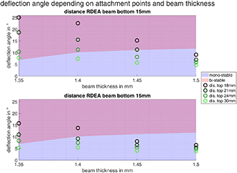
Figure 15. Parameter study on the T-platform: correlation deflection angle and beam thickness.
Download figure:
Standard image High-resolution imageIn conclusion, we have verified experimentally that, in order to maximize the actuation performance, one should move the RDEAs as close as possible to the beam and select a sufficiently thin beam. This combination of parameters will favor buckling which, in turn, leads to a large bending performance. The buckling, however, should not be favored too much, otherwise the actuation becomes irreversible, causing the system no longer to snap when the opposite RDEA is activated. The optimal trade-off between large bending angle and reversible actuation can be tuned via an appropriate choice of the free parameters, and can be eventually supported by the proposed physics-based model. Those finding will provide useful guidelines for the design of future soft tentacle arms based on stacks of many T-platforms.
5.3. Suitability for soft robotics applications
To conclude this section, we investigate the suitability of the T-platform for soft robotic applications. To this end, we perform experiments aimed at evaluating the prototype compliance when subject to an external deformation, since this property is important to ensure a safe human-robot interaction. To measure the T-platform compliance, the setup shown in figure 16 is used. A steel rope (depicted in red) is wired parallel to the left RDEAs, the rope is connected to a load cell (ME-Meßsysteme KD40s) via pulleys. This load cell is mounted on a linear drive, whose displacement can be arbitrarily prescribed.

Figure 16. Experimental setup to measure the mechanical compliance.
Download figure:
Standard image High-resolution imageIn order to measure parameters related to the structure mechanical compliance, tensile experiments are carried out for both mono- and bi-stable configurations (mono-stable: c = 18 mm, a = 18 mm, tB= 1.4 mm; bi-stable: c = 24 mm, a = 18 mm, tB = 1.4 mm). By prescribing a deformation profile to the linear actuator, the structure bends accordingly. During this process, we acquire the force of the load cells, as well as the angle of the rigid spacer mounted at the top of the flexible beam. In order to extract a meaningful compliance measure from those data, we use standard rigid body dynamics to convert the forces to the equivalent moment applied to the center of mass of the rigid spacer. In this way, we can plot the moment as a function of the bending angle, and extract the angular compliance by measuring the slope of this diagram. The corresponding plots are shown in figure 17.
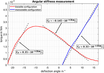
Figure 17. T-platform angular stiffness measurement.
Download figure:
Standard image High-resolution imageFor the monostable case, there is a linear relationship between the deflection angle and the torque. The corresponding angular stiffness is CT = 0.33 × 10⁻³ Nm/°. In contrast, the bi-stable design results in a non-linear relationship with a region of positive stiffness (CT = 0.35 × 10⁻³ Nm/°) and a region of negative stiffness (CT = −0.15 × 10⁻³ Nm/°). This behaviour is equivalent to that of a mono- and bi-stable biasing mechanism with an LBS or NBS in single-DoF. For comparison, the angular stiffness of the human muscle in the elbow is in a range of CTmin = −0.35 Nm/° up to CTmax = 0.35 Nm/° [42]. Therefore, our T-platform is softer by a factor of 103 compared to human muscles, thus confirming its suitability for soft robotics and safe human-robot collaboration.
6. Conclusion
In this work, the first concept of a bendable soft robotic module, consisting of a pair of silicone-based RDEAs actuating a flexible T-platform, was presented and experimentally validated for the first time. The influence of the free design parameters (i.e. beam thickness, RDEA upper and lower mounting points) on the bending angle performance was systematically investigated by means of both simulation studies and experimental investigations. It was found that the bending angle strongly depends on such parameters, and can range between 5° and 25° for the considered parameter space, given the same RDEA geometry and actuation voltage. A good adherence is also observed between simulations and experiments, thus confirming the proposed model as a valuable tool to optimize the T-platform performance. It was also found that, for some combinations of parameters, the system exhibits a controllable bi-stable behavior which, in turn, results in much larger bending angles compared to mono-stable configurations. These findings confirm that, similar to what happens to single-DoF DEAs, bi-stable biasing concepts can be also successfully used to increase the performance of multi-DoF DE structures. The bi-stability also makes it possible to keep the robot in a deformed state without spending electric energy, while mono-stable configurations require a continuous supply of electric power to maintain a desired deflection. These findings confirm that, similarly to what happens to single-DoF DEAs, bi-stable biasing concepts can be also successfully used to increase the performance of multi-DoF DE structures. For the best possible combination of parameters, the maximum deflection angle could be increased up to 25°. Such a value is more than 2.5 larger than our previous concept for silicone-based DE rotational module, which could only bend up to 9.6° for the best possible combination of design parameters [30]. Finally, angular compliance measurements confirmed that our T-platform is softer than human muscles by a factor of 103, thus confirming its suitability for soft robotic applications.
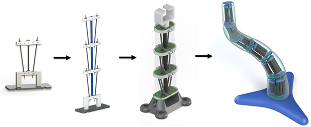
The promising performance of the considered T-platform opens up several possible future directions for our research. Full DE soft tentacle arms will be developed based on stacks of several T-platforms, as shown in figure 18. Stacking several modules presents new challenges for the design. In this case, in fact, the influence of the weight and moment of the upper platforms must be balanced out by the lower platforms, and electrical contacts to the upper modules must also be ensured. Thus, in the future, scaling the force by bundling RDEAs, and finding new ways to contact them electrically, will also be important points to investigate. Scaling the force will also allow the robot arm to adapt to real applications, which involve manipulation of objects. Regarding this aspect, external load forces and moments are also expected to impact the system bi-stability, so that their effects will be explicitly investigated (and accounted for) in future designs. The bi-stable design will also be extended beyond the planar actuation, in order to enable bending along all spatial directions. At the same time, the model will be also validated in a dynamic setting, and will be used to develop motion/interaction control strategies as well as self-sensing estimation of the robot configuration. In this way, we will be able to achieve proportional stabilization of intermediate angles, and thus achieve proportional control of the bending angle while keeping the large displacement benefits of the bi-stable design.
Figure 18. Future planned development steps in the way to a DE-based soft robot arm.
Download figure:
Standard image High-resolution image
Acknowledgments
The authors gratefully acknowledge the support of the Deutsche Forschungsgemeinschaft (DFG, German Research Foundation) through Priority Program SPP 2100 'Soft Material Robotic Systems' (Projects: SE704/6-1, RI3030/1-1).
Data availability statement
All data that support the findings of this study are included within the article (and any supplementary files).
Appendix.: Parameters used in the simulation study
Top plate parameters: mTP = 12 g, g = 9.81 m s−2.
Structure parameters: b = 15 mm, btop = 15 mm, lcr = 13.8 mm.
Beam parameters: lB = 110 mm, wB = 10 mm, EB = 1.9 GPa.
RDEA parameters: L1 = 68.2 mm, L2 = 78 mm, L3 = 47.6 μm, C10 = 218 000 Pa, C20 = −24 000 Pa, C30 = 16 000 Pa, αe 1 = 0.74, ηb = 0.74, εr = 2.8, ε0 = 8.85 × 10⁻¹² F m−1.