

Abstract
Smart materials and structures have developed rapidly, especially their application in the aerospace field has been widely valued and recognized in recent years. Shape memory cyanate ester (SMCE) resin as a class of smart polymers has a broad application prospect in space deployable structure due to the high glass transition temperature (Tg) and excellent mechanical properties. In this work, the SMCE resins were prepared by regulating cyanate prepolymer with small molecules, showing high Tg (> 218 °C) and high storage modulus (E' > 3.15 GPa). The SMCE resins maintained a high shape fixity rate (Rf > 95%) at high operating temperatures (100 °C and 120 °C) for 30 d, providing a great potential application for active deformation structures. Moreover, the synergy of carboxyl (–COOH) functionalized multi-walled carbon nanotubes and short carbon fiber enhanced the thermodynamic properties and shape-changing function of the SMCE composites. The spring made by SMCE composite exhibits 360° freedom rotation, which can be used as smart structures in the aerospace field.
Export citation and abstract BibTeX RIS
1. Introduction
Shape memory polymer (SMP) is a kind of smart material, which has the advantages of large strain and low density. It has broad application prospects in space deployable structures [1–4]. Cyanate ester (CE) is considered as one of the ideal resins for aerospace structural materials due to its excellent thermal stability, high Tg , low moisture absorption and coefficient of linear expansion [5–8]. During the service of spacecraft, it is strongly affected by various space environment factors, such as high vacuum, atomic oxygen (AO), cold and thermal cycle, radiation, ultraviolet (UV) radiation and space debris [9–13], which will lead to the performance degradation of polymer materials. The environment is one of the main reasons that affect the reliability and life-span of spacecraft and induce the performance degradation of spacecraft materials. Therefore, it is necessary to study space radiation, especially the γ-ray damage mechanism of SMCE. The interaction behaviors between different particles and irradiated materials are different, but their mechanisms of destruction are similar [14–17], So far, the research on radiation damage of CE resin mainly focuses on thermal degradation and outgassing [18–21].
In addition to the damage mechanism, the effects of irradiation on shape memory performances of SMPs have also attracted attention. Hou et al [22] found that the Rf of epoxy-based SMP was almost constant at approximately 99.6% and the Rr decreased sharply after 1 MeV electron radiation. They also found that the Rr of shape memory epoxy (SMEP) resin decreased exponentially with decreasing electron dose rate [23]. Furthermore, the Rf of SMEP resin had an almost negligible reduction after 1 MeV proton radiation. However, the Rr decreased significantly [24]. Leng et al [25] indicated the Rr of SMEP resin was greater than 95%, which meant that γ-ray radiation had little effect on Rr . Gao et al [26] demonstrated that the shape memory polyimide films could maintain Rf and Rr even after 30 cycles under AO and UV irradiation and space thermal cycling environments. Xie et al [27] pointed out that AO had no adverse effect on the shape memory performance of cyanate-based SMP. There is little research has been done on the degradation of SMCE resins, especially on Rf .
The space environment in which the spacecraft in service is not static, particularly the ambient temperatures. The temperature differences can reach hundreds. How can a device made of resin composites be kept in a stable structure in such a volatile environment? Resins that maintain a high Rf at high temperatures can meet this requirement. Therefore, it is a new challenge to develop this kind of polymer. It is well known that the shape fixing behavior of polymers is caused by the storage of strain energy in the chain segments between crosslinking points [28, 29]. The high Rf depends on the high homogeneity distribution of the chain segments [30], which shows that the smaller the half peak width of tan δ peak is, the higher the temperature is. Moreover, the high stiffness of the chain segments is unfavorable to shape fixing. Therefore, low molecular weight modifiers containing flexible chain segments are expected to enable SMCE resin to exhibit excellent shape-fixing behavior at high operating temperatures.
In this work, polyethylene glycol diglycidyl ether (PEGDGE) with low molecular weight and flexible chain, was selected to modify the CE resin to give the resin anticipated shape fixing property at high temperatures. The mechanism of degradation and damage of SMCE resin by γ-ray irradiation was studied, furthermore, the mechanical properties, thermal stability, mass loss and shape memory properties of the SMCE resin under γ-ray irradiation were analyzed systematically. The thermal conduction pathways jointly constructed by carbon nanotubes (CNT) and carbon fiber (CF) are conducive to heat conduction and improve the shape recovery performance of the SMCE resins. The flexible spring arm with free deformation, which is made of CNT and CF reinforced CE composites, is designed to meet the requirements of space applications.
2. Materials and methods
2.1. Materials
Bisphenol-A CE prepolymer was purchased from Yang Zhou Chemical Industry Park, Jiangsu, China. PEGDGE (average Mn 500) and Benzophenone (BP) were purchased from Sigma-Aldrich. Carboxyl (–COOH) functionalized multi-walled CNT and short CF were obtained from the Chinese Academy of Sciences Chengdu Organic Chemistry Co. Ltd., China.
2.2. Preparation of CE resin and their composites
CE resin: a certain amount of Bisphenol-A white particulate cyanate ester monomer (CEM) was placed in a clean beaker and then dissolved into a liquid at 120 °C. Keep heating while slowly stirring for 72 h to prepare CE prepolymer. Then, the CE prepolymer was heated to 50 °C in a beaker. PEGDGE was added to the beaker with stirring continuously to obtain a homogeneous solution, namely resin precursor. The mass ratios of CE prepolymer and PEGDGE are 5:1 and 10:1, which were cured at 180 °C for 3 h and then 210 °C for 3 h. The CE and CE' resin plates were obtained.
CE composite: 0.5 wt%, 1.0 wt% and 2.0 wt% CNT or CF was added into the resin precursor, respectively, stirring for 2.0 h at 50 °C and 1.0 h at room temperature, and the CNT doped CE resins (CE-0.5CNT, CE-1.0CNT and CE-2.0CNT) and the CF doped CE resins (CE-0.5CF, CE-1.0CF and CE-2.0CF) were obtained. 2.0 wt% CNTs and 2.0 wt% CFs were added into CE precursor with stirring for 2.0 h at 50 °C and 1.0 h at room temperature, and CE/CNT/CF composite (CECCC) was obtained.
Springs: As shown in figure 1, the precursor was injected into a silicone hose with a 3 mm inner diameter and 5 mm outside diameter by the syringe. The silicone hose filled with resin precursor was convolved around a graduated column and fixed with 5 mm or 10 mm screw pitch, and then was cured at 180 °C for 3 h and 210 °C for 3 h. Remove the silicone hose to obtain the spring.
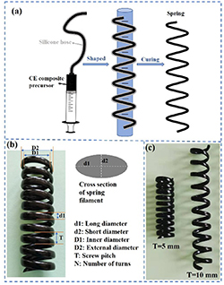
Figure 1. (a) The manufacturing process of a spring. (b) The prepared spring and its parameters. (c) The prepared springs with 5 and 10 mm screw pitches.
Download figure:
Standard image High-resolution image2.3. Space environmental exposure test
The orbital environmental parameter of the space station truss structure for 30 years' electron radiation is 104~105 Gy [25, 31]. The SMCE resins were irradiated by the 60Co radiation source, which was provided by the Heilongjiang Academy of Sciences (Harbin, China). Moreover, the effect of a higher dose (106 Gy) of γ-ray on the CE resin was also studied. The SMCE resins irradiated by 104, 105 and 106 Gy are called IR1-CE, IR2-CE and IR3-CE, respectively. The dose rate is 5.0 Gy s−1and the irradiation time is 2000 s, 20 000 s, 200 000 s, respectively.
2.4. Characterization and measurements
The x-ray diffraction (XRD) analysis was characterized using a Rigaku Miniflex Japan. The CE film samples were tested by Fourier Transform Infrared Spectroscopy (FTIR, Perkin Elmer Corp., US). Dynamic mechanical analysis (DMA) of the resins was carried out using the DMA Q800 apparatus (TA Corp., US) with a 1 Hz frequency. Thermogravimetry analysis (TGA) of the samples was carried out using an analyzer (Mettler-Toledo, Switzerland) from 25 °C to 800 °C with a 10 °C min−1 ramp rate. The mechanical properties of CE resin specimens were characterized using an Instron 5500 R Universal Testing Machine (Instron Corp., USA). A rheological test of CE prepolymer was carried out by DHR Discovery (TA Corp., US) with a 25 mm parallel plate clamp and 1000 µm working gap. The surface and cross-section morphologies of SMCE resins and composites were exposed using a scanning electron microscope (SEM) (JSM-7600F, JEOL Ltd.). The samples were sputtered with gold for 30 s before observation. The thermal conductivity of the specimens was tested by LFA 457 laser thermal conductometer (Netzsch, Germany).
3. Results
3.1. Curing of the SMCE resin and composites
There are two cyano-groups in a CEM molecule. Three neighboring cyano-groups can be self-polymerized to form a triazine ring structure without any catalyst or curing agent. The diagrammatic drawing of the self-polymerization reaction is shown in figure 2(a). The rhombuses represent cyano-groups, and the hexagons represent triazine rings as the connection points of the network structure. The CE resin has high strength, which is due to the high content of triazine rings. However, highly symmetrical structures of the triazine rings lead to the brittleness of pristine CE resin. The toughness of CE resin can be improved by inhibiting the formation of the triazine ring structure.
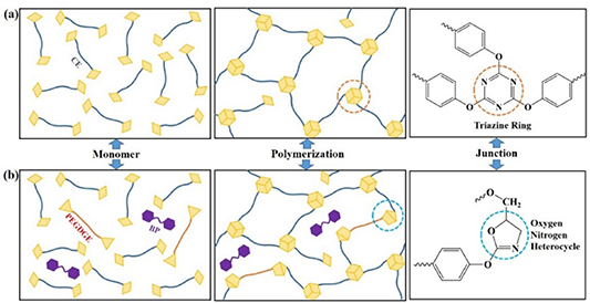
Figure 2. Schematic diagram of the cross-linking structure of pure CE resin (a) and modified CE resin (b).
Download figure:
Standard image High-resolution imagePEGDGE is an epoxy-terminated liner monomer, whose addition prevents the self-polymerization reaction of some cyano-groups. The cyano-groups react with epoxy groups to produce five-membered oxygen-nitrogen heterocycles (ONHCs) as shown in figure 2(b). The producing mechanism of ONHCs was reported in our previous work [32]. Compared with the triazine rings, the ONHCs have higher activity. Therefore, the ONHCs are more likely to be damaged by γ-rays than the triazine rings. Another modifier is BP, which almost did not participate in the chemical reactions during the curing process. The interaction with other components is primarily intermolecular force. The main role of BP is to reduce the stiffness difference between PEGDGE and CE resulting in high homogeneity distribution of molecular chains of all components.
The prepared resin precursor is a mixture of CE prepolymer and modifiers, whose thermal analyses, rheological and curing properties are shown in figures S1 (available online at stacks.iop.org/SMS/31/045010/mmedia) and 3(a), (b). The viscosity decreases with the increase of shear rate, which is consistent with the shear-thinning characteristic of liquid polymer. The initial viscosity of the resin precursor is 177.0 Pa·s. The resin precursor has a high viscosity and poor fluidity at room temperature, which is not suitable for molding. The complex viscosity of the resin precursor varies with curing temperature. The inset curve clearly shows that the complex viscosity increases distinctly when the curing temperature is above 202 °C. Therefore, we set the curing temperature of the resin precursor at 210 °C.
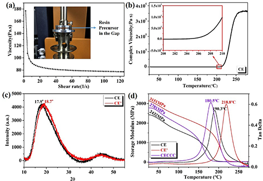
Figure 3. (a) The shear-thinning behavior of resin precursor; (b) The viscosity-temperature curve during polymerization; (c) XRD patterns of CE resins; (d) The modulus and tan δ curves concerning the temperature of the resins.
Download figure:
Standard image High-resolution imageThe curing is accompanied by the formation of network structures in the resin where crosslinking points are hard segments, such as triazine rings and ONHCs, and the molecular chains between the crosslinking points are soft segments. Two samples (CE resin and CE' resin) were prepared by adjusting the ratio of CE prepolymer to PEGDGE. The wide-angle XRD method is to analyze crystallinity and phase of the cured resins with 2.0 mm thickness. Two broad peaks can be observed at around 18° and 45° (2θ) of XRD patterns (figure 3(c)) indicating poor crystallinity of the resins [33, 34]. The 0.8° shift indicates that covalent bonds in CE resin are shorter than that in CE' resin. The CE' resin is expected to have higher hardness than the CE resin. The DMA curves (figure 3(d)) show that the E' is 2432 MPa for the CE resin and 3151 MPa for the CE' resin at 25 °C. The peak of tan δ is labeled as Tg , which is 190.3 °C for the CE resin and 218.8 °C for the CE' resin. CNT and CF are added to the resin precursor to enhance the mechanical properties and thermal conductivity of the resins. CNT as conductive filler formed the main thermal conductivity channels in the CE matrix. CF was introduced to repair defects in conductivity channels and networks. Tg of CECCC is 180.5 °C which is 10 °C lower than that of CE, and E' of CECCC is 2781.0 MPa which is about 350 MPa higher than that of CE.
In addition, the tensile test result of CE specimens doped with different content of CNT is shown in figure S2. The addition of 0.5 wt% and 1.0 wt% CNT increased the CE resin's tensile strength and fracture elongation, while 2.0 wt% CNT decreased the fracture elongation of the resin. 2.0 wt% CNT has negative effects on mechanical properties of the CE resin, indicating potential agglomeration at a high CNT content. To confirm the synergetic enhancements, the thermal conductivity was investigated and exhibited in table S1. The thermal conductivity of the CE resin is 0.206 W ((m*k)−1) and that of the CE resin doped with 2.0 wt% CNT is 0.278 W ((m*k)−1), which demonstrates that CNT is not sufficient to form the thermal conductivity channels in the CE matrix. The thermal conductivity of the CE resin doped with CNT and CF is about twice as much as that of the CE resin. The CF is bridged with CNT nearby, forming the thermal conductivity channels.
3.2. Thermodynamic properties of the SMCE resins and composites
The physical properties of the CE resin change after γ-ray radiation. The mass of CE specimens increases with the increasing irradiation dose as shown in figure 4(a). The mass increases by more than 0.2% for IR3-CE. Ionics and free radicals produce under γ-ray radiation, and the radiation-induced free radicals undergo chemical reactions with oxygen resulting in increasing mass [35–37]. In addition, the four specimens change in color from wine red to orange-red as the inset is shown. The effect of γ-ray radiation on the mechanical performances of the CE renin is also concerned. E' and tan δ with temperature curves of the CE, IR1-CE, IR2-CE and IR3-CE resins are shown in figure 4(b) and table S2. The E' is increased by about 200.8 MPa after 106 Gy γ-ray radiation, which means the capacity to store strain energy increases. The Tg shifts to lower temperature after 106 Gy γ-ray radiation, which decreases from 190.3 °C to 186.2 °C. The decrease is caused by the breaking of molecular chains between crosslinking points in the CE resin.

Figure 4. (a) The mass variation of CE resin after irradiation; (b) E' and tan δ values versus temperature of the CE resin and irradiated CE resin; (c) Stress–strain behaviors of the resins and their composites; (d) Stress–strain behaviors of the CE resin before and after γ-ray irradiation.
Download figure:
Standard image High-resolution imageThe tensile test is to characterize the mechanical properties of the resins, which can analyze the tensile strength and toughness of the resins. The stress–strain curves of CE, CECCC, CE' and CE'/CNT/CF composite (CE'CCC) specimens tested at 25 °C or high temperature (Tg of the specimen) are present in figure 4(c). The curves of the CE and CECCC specimens reveal a 0.4% decrease of elongation at break and a 10.9 MPa increase of tensile strength after the addition of CNT and CF. And the curves of the CE' and CE'CCC specimens show a 0.6% increase of elongation at break and a 7.0 MPa increase of tensile strength after the addition of CNT and CF. To summarize, the synergistic effect of CNT and CF improves the tensile strength and has little effect on fracture elongation. Figure 4(d) records that the elongation at break increases from 4.81% to 5.93% after 106 Gy γ-ray radiation, which is caused by the destruction of molecular chains between the crosslinking points and then the slip of the molecular chain under the stress.
The thermal stability of the CE resin is influenced by γ-ray which can be revealed by TGA. Figures 5(a) and (b) show the TGA curves of CE specimens at different γ-ray doses measured in a high-purity air and N2 atmosphere. The initial thermal decomposition temperature (T5%) is defined as the temperature at which the weight loss is 5%. T5% of the CE resin is 324.7 °C. T5% of the CE resin is 324.7 °C which decreases gradually with the increasing radiation dose. When the γ-ray dose is 106 Gy, T5% is 297.0 °C. The decomposition process is endothermic on the whole as shown in figure S3. There is an exothermic peak in the heat flow curves at 520 °C~600 °C which is attributed to the decomposition of triazine rings [38, 39]. When the temperature exceeds 650 °C, the weight is no longer reduced, so the curve shows a plateau stage. The carbon residue ratio of the four specimens is 1.4%, 1.5%, 1.1% and 0.6% at 800 °C, respectively. The results show that the carbon residue ratio decreases with the increasing radiation dose. The cross-linking structure of SMCE resin is destroyed by high-energy γ-ray radiation, which leads to the reduction of crosslinking density and thermal stability of SMCE resin. The decomposition in N2 is different from that in air. T5% of CE resin increases from 284.9 °C to 352.8 °C with the increasing γ-ray dose. The carbon residue rates of CE, IR1-CE and IR2-CE are almost the same, about 23.6%, and that of IR3-CE is 19.2%, which indicates that the carbon skeleton of the CE resin is difficult to decompose in the N2 atmosphere, and part bonds on the carbon skeleton are destroyed by 106 Gy γ-ray.
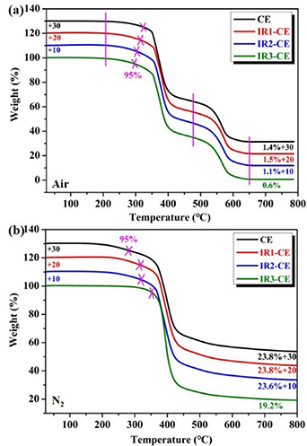
Figure 5. TGA curves of the SMCE resin before and after γ-ray irradiation in the air (a) and N2 (b) atmosphere.
Download figure:
Standard image High-resolution imageThe chemical bond changes in the irradiated resins can be seen in FT-IR spectra. Figure S5 demonstrates the FT-IR spectra of CE, IR1-CE, IR2-CE and IR3-CE. The peaks at 2968 and 2871 cm−1 are attributed to C–H stretching vibration in –CH3 and –CH2–. The two peaks at 1564 and 1366 cm−1 can be corresponding to 1,3,5-triazine groups [40] and the peak at 1503 cm−1 belongs to the benzene ring [5]. There is no new peak after γ-rays radiation and a slight change in peak intensity which is probably caused by the differences in film thickness.
3.3. Surface morphologies of the SMCE resins
SEM was used to evaluate the influence of γ-ray radiation on the surface morphology of the CE resin. Backscattered electron (BSE) images of surface morphology and cut surface morphology of the CE specimen and the IR3-CE specimen are shown in figure 6. The mold caused some scratches on the surface during preparation and the magnified images of CE and IR3-CE have no significant difference. The CE and IR3-CE specimens are cut and the enlarged views of the cut surfaces show no significant difference. In addition, secondary electron (SE) images of surface morphologies and cross-section morphologies of the CE and IR3-CE specimens are shown in figure S6. The surface of the CE plate is smooth and has no changes after irradiation as shown in figure S6(a). The cross-sectional images in figure S6(b) are the sections of CE and IR3-CE specimens after the tensile test. The section cracks are similar in the two images, which are low in sharpness and diffuse. The section morphologies are rough and show the characteristics of feather fracture with high toughness and high strength, so the brittleness of the material is low and the plastic deformation is significant. It indicates that the added linear monomer has entered the crosslinking network structure of cyanate ester, resulting in increased flexibility and enhanced toughness of the material. Nevertheless, some differences could be found in the two enlarged images. There are micro-pits and tensile tear stripes in the radial extension zone near the fracturing source for the IR3-CE specimen, showing obvious ductile fracture characteristics.
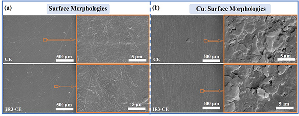
Figure 6. BSE images of (a) surface morphology and (b) cut surface morphology of the CE and IR3-CE specimens.
Download figure:
Standard image High-resolution imageThe surface chemical compositions and atomic valence states of the CE resin before and after γ-ray radiation are analyzed by XPS. The C1s peak curves are shown in figure 7. The raw peak is split into three sub-peaks, then the three sub-peaks are fitted into a peak (red curve). The location and area proportion of the three subpeaks are listed in table 1. The sub-peaks located at 284.6 eV, 285.5 eV, 288.6 eV are assigned to C–C/C–H, C–O and C=O/O–C=N bonds, respectively [41–43]. As γ-ray increased, the proportion of C=O/O–C=N peak area decreases significantly from 8.7% to 2.8%, which is caused by the synergistic action of C=O bonds and O–C=N bonds. The C=O bond in the CE resin is broken and its ratio is reduced by γ-ray radiation. The formation of triazine rings and oxygen-nitrogen heterocyclic rings is the direct cause of the increased ratio of O–C=N bond during irradiation. As γ-ray increases, the proportion of C–O peak area increases slightly from 34.8% to 36.5% and that of C–C/C–H peak increases from 56.5% to 60.7% indicating the destruction of C–O bonds and C–C/C–H bonds by γ-ray. C–O bond in PEGDGE may dissociate after γ-ray radiation, which means the crosslinked network of the CE resin is destroyed to some extent and the ability of segment motion is enhanced.

Figure 7. XPS spectra of C1s after (a) 0 Gy, (b) 104 Gy, (c) 105 Gy, (d) 106 Gy γ-ray radiation.
Download figure:
Standard image High-resolution imageTable 1. Characteristics of the peak in XPS C1s spectra for epoxy-based shape memory polymer before and after γ-ray radiation.
| Samples | Bonds | Binding energy (eV) | Proportion (%) |
|---|---|---|---|
| CE | C=O/O–C=N | 288.6 | 8.7 |
| C–O | 285.5 | 34.8 | |
| C–C/C–H | 284.6 | 56.5 | |
| IR1-CE | C=O/O–C=N | 288.8 | 5.7 |
| C–O | 285.5 | 36.6 | |
| C–C/C–H | 284.6 | 57.7 | |
| IR2-CE | C=O/O–C=N | 288.8 | 3.7 |
| C–O | 285.5 | 37.0 | |
| C–C/C–H | 284.6 | 59.3 | |
| IR3-CE | C=O/O–C=N | 288.8 | 2.8 |
| C–O | 285.5 | 36.5 | |
| C–C/C–H | 284.6 | 60.7 |
3.4. Shape memory properties of the SMCE resins
The tan δ peak width at half height (W) is labeled in figure S7, which is related to the shape memory performances of the resins. The smaller W is, the less transition time between glassy state and rubbery state is. Moreover, the shape recovery process is fast and the Rf is higher. W is 27.7 °C for the CE resin and 25.4 °C for the CE' resin, which demonstrates that the shape fixing performance of the CE' resin is better than that of the CE resin.
New cross-linking points and molecular fragments generate in the process of γ-ray irradiation, which makes a difference to Rf and Rr. Rf and Rr of the CE and IR3-CE specimens are measured by stretch-recovery cycles. The chains become more active when the resin is heated and become more ordered during stretching. Four tensile cycles of the CE and IR3-CE resins were performed as shown in figures 8(a) and (b). Rf and Rr of the cycles are calculated by equations (1) and (2):
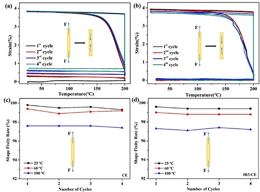
Figure 8. Tensile memory performance of the CE resin (a), (c) and the irradiated CE resin (b), (d).
Download figure:
Standard image High-resolution image
where  and load are the strain after unloading and the maximum strain under load, respectively. rec is the strain after shape recovery and is the strain at the beginning of every cycle.
Rf of the CE and IR3-CE resins at different test temperatures (at 25 °C, 60 °C, 100 °C) is shown in figures 8(c), (d) and table S3. Rf (at 25 °C) of the CE resin decreases from 99.6% to 99.5% after irradiation, and Rf (at 100 °C) decreases from 97.6% to 97.3%. The decrease is attributed to soft segments destroyed by γ-ray radiation. The reason for the decrease is that the potential energy storage capacity of the soft segments is weakened due to γ-ray radiation. Moreover, the Rr of every cycle is listed in table S4. The average Rr is 95.8% for the CE resin and 98.9% for the IR3-CE resin at 25 °C. Rr is affected by the crosslinking points in the network structure. Rr of the CE resin increases after γ-ray radiation. The unreacted functional groups in the resin undergo secondary crosslinking under γ-ray radiation increasing cross-linking points, which increased the recovery force and Rr of the CE resin.
In addition to the stretch mode, Rf of the samples at bend mode is tested at different temperatures for 30 d. 'U' is a temporary shape of the CE resin. Rf and Rr are calculated by equations (3) and (4), respectively. The results are shown in figure 9 and table S5:

Figure 9. Rf of the CE resin (a) and the IR3-CE resin (b) at bending mode.
Download figure:
Standard image High-resolution imagewhere θ is the shape recovery angle. Rf decreases and then levels off with time. Rf of the CE resin is more than 99.2% at 25 °C, 97.9% at 60 °C and 95.6% at 100 °C on the 30th day. Rf of the IR3-CE resin is more than 99.0% at 25 °C, 97.3% at 60 °C and 94.8% at 100 °C. The comparison demonstrates that γ-ray radiation will slightly reduce the Rf due to the damage of soft segments in the CE resin, which is consistent with that in the stretch mode.
The recovery processes of the CE and IR3-CE resins are within 15 s and are shown in figures 10(a) and (b). The shape recovery angle of the CE resin is about 1° at 15 s and its Rr reaches up to 99.4%. The shape recovery angle of the IR3-CE resin is about 3° and its Rr is about 98.3%. The results demonstrate that irradiation has a negative effect on the Rr of the CE resin due to the destruction of molecular chains between the crosslinking points. The shape recovery angle of CECCC) is about 2° at 15 s and its Rr reaches up to 98.9% as shown in figure 10(c), which is slightly lower than the Rr of the CE resin. However, the shape recovery of CECCC shows a significant advantage at 2, 5 and 10 s compared with that of the CE resin, which is caused by the addition of CNT and CF.

Figure 10. The shape recovery process of U-shape specimens at 190 °C.
Download figure:
Standard image High-resolution imageA spring-based elastic arm is designed, which is inspired by flexible manipulators. As shown in figure 11(a), the curves show stress–strain behaviors of the two springs with 5 and 10 mm screw pitches, which are almost straight lines. The fracture strain of the spring with screw pitch 10 mm is 100% and that of the spring with screw pitch 5 mm is over 150%. The spring can be used for extension flexible arms to grasp objects, which not only can stretch and contract, but also has the bending function.

Figure 11. (a) The tensile fracture behavior behaviors of the stretched springs; (b) The shape recovery process of the spring in the space; (c) and (d) The spring elastic arm.
Download figure:
Standard image High-resolution image
In the space coordinate system, the X-axis act as the axle wire of the spring and one end is located on the original point (O) as shown in figure 11(b). Shape recover spring could store strain energy, controllably release energy and possess super deformation ability in space compared with common spring, which has a characteristic of variable stiffness. The E' of the CE composite decrease with temperature increases. The stiffness degradation is conducive to deform. It can bend in any direction, and it also can be compressed and stretched. The forming temperature is 180 °C and then the bent spring is cooled to 25 °C. The shape recovery temperature is set to 170 °C which is lower than Tg , resulting in the spring retaining a certain rigidity to overcome its gravity. The flexibility of the spring gives the spring unlimited potential as an elastic arm. As shown in figures 11(c) and (d), the elastic arm consists of a spring, a woven net and a claw. The net is stretchable and has a good match with the spring. The elastic arm can be stretched or compressed to grab and hold objects, such as the end of service aircraft and debris in space.
4. Conclusion
The shape memory CE resins were prepared by introducing functional modifiers into the cyanate prepolymer. The CE resin was exposed to 106 Gy γ-ray, whose Tg decreased from 190.2 °C to 186.2 °C and elongation at break increased by 22.9%. T5% of the CE resin dropped from 324.7 °C to 297.0 °C after γ-ray irradiation and the residual carbon rate decreased from 1.4% to 0.6% at 800 °C. In addition, the CE resin demonstrates excellent shape memory behaviors. The CE resin has a high Rf of 95.6% at 100 °C for 30 d. The multiscale fillers (CNT and CF) jointly construct thermal conductivity channels to enhance the thermal conductivity of the CE resin improving the shape recovery efficiency. The SMCE resin and its composites with excellent Rr and Rf at high operating temperatures show more advantages than most common thermosets. The elastic arm made of CNT/CF doped CE resin is expected to stand out in deployable space structures.
Acknowledgments
This work is supported by the National Natural Science Foundation of China (Grant No. 11632005).
Data availability statement
All data that support the findings of this study are included within the article (and any supplementary files).