

Abstract
This paper presents a pneumatic colonoscopic robot with tactile sensing and shape-locking abilities. With the integration of a helical rotating propulsion module, a specially designed soft-sensing module, and a wire-tension-based shape-locking module, the proposed robot achieves excellent efficiency, visualization quality, and safety. The propulsion module can generate a helical rotating motion in tubular environments with good adaptivity to rigid, flexible, vertical, and elbow tubes. The sensing module, employing a specially designed soft sensor based on conductive rubber, can monitor the contact status between the robot and the environment to avoid slippage and reduce discomfort to patients. In conjunction with actuating balloons, the shape-locking module can keep the robot in any helical formation, which allows the camera attached to the robot to obtain a stable view. Experimental results show that the robot has great adaptability to tubes of different diameters (26–32 mm) and considerable propelling velocity (as fast as 20 mm s−1 with 30 mm tube diameter). The feasibility and practicability of the sensing module and shape-locking module are also demonstrated. A screening test in a simulated colon tube validates its excellent comprehensive performance and indicates good potential for the proposed robot.
Export citation and abstract BibTeX RIS
1. Introduction
According to global cancer statistics 2018 [1], colorectal cancer ranks third in terms of incidence and second in terms of mortality worldwide. There is evidence to suggest that regular screening is one of the best and most effective methods of preventing it [2]. However, conventional push-type colonoscopy is not widely accepted as an effective diagnostic technique because the procedure often brings considerable discomfort to patients, and the operation is cumbersome [3, 4]. Finding a more comfortable and convenient alternative to conventional colonoscopies would increase participation in regular screenings, which would help to reduce the incidence and mortality rate from colorectal cancer.
Developing active propulsion techniques in colonoscopy is considered critical for improving conventional colonoscopies [5]. Based on their propulsion mechanisms, existing self-propelling colonoscopic devices can be classified into four main types: wheeled, legged, screw-based, and worm-like devices.
Wheeled devices [6, 7] can advance relatively smoothly in the colon at a high speed, facilitating efficient colonoscopy with low invasiveness. To gain traction and avoid scratching the inner wall of the colon, the devices are usually equipped with many wheels or tracks [8]. This complicated structure makes sterilization difficult. Additionally, the devices cannot adapt to changes in the diameter of the colon without an auxiliary mechanism, which further complicates their structure [9].
Legged devices [10, 11] usually employ several leg-like protrusions to advance in a cyclical walking motion through the colon. These protrusions generate better traction and adapt better to diameter variations of the colon than wheeled devices [12]. However, there is a high risk of trauma due to the small contact area between the leg-like protrusions and the inner wall of the colon.
Screw-based [13, 14] devices, with spiral protrusions on their surface, advance in the colon in the same way as a bolt moves in a threaded hole. This propulsion method is very stable, and these devices are of a relatively simple structure. However, the devices rub against the inner wall of the colon during propulsion, generating a large friction force and often causing considerable discomfort or even trauma to patients. Moreover, their fixed size makes them unadaptable to diameter variations of the colon.
Worm-like devices are inspired by worms such as the inchworm [15, 16] and earthworm [17, 18]. Most of these devices have flexible bodies and are driven pneumatically; thus, they are safer than the other types of devices. Among them, devices inspired by the earthworm are inefficient for screening colonoscopies because their propulsion velocity is relatively low. A full-driving soft robotic colonoscope has been proposed inspired by the earthworm, but its top velocity is less than 2.5 mm s−1 [19]. The inchworm-inspired devices have better potential in colonoscopy because of their efficiency and elegance of structure. Generally, inchworm-inspired devices consist of two anchoring segments and one propulsion segment [20, 21]. To achieve effective propulsion, the anchoring segment often has to be greatly deformed to avoid slipping. As a result, the colon is under great pressure as it is deformed correspondingly, increasing the patient's discomfort during the procedure.
In addition, some other propulsion mechanisms are also used in self-propelling devices for tubular environments. A twisted bundled tube locomotive device can advance in pipes by helical rotation, which generates propulsion by revolving its whole body [22]. A snake-like robot with 13 links has been developed by applying the 'sinusoidal wave drive' principle and can advance in curved pipes and pipes of varying diameters [23]. However, these devices were not developed for colonoscopy, and the applicability of their propulsion mechanisms to flexible tubular environments has not been demonstrated.
In general, the above self-propelling devices have various problems in their propulsion methods that cannot be ignored for colonoscopy. Furthermore, although most of these devices offer active propulsion, because of the lack of force/tactile sensing, there is considerable risk of discomfort or even damage to patients during the propulsion process. An alternative method with satisfactory efficiency, quality of visualization, and especially tactile sensing ability to ensure safety and minimization of discomfort to patients needs to be developed.
In this paper, a shape-lockable self-propelling robot with tactile sensing for inspecting the large intestine was developed based on helical rotating motion. The device consists of a propulsion module, sensing module, and shape-locking module, which are integrated through a novel helical structure. The main features and contributions of each module are as follows:
- Propulsion module: the helical rotation employed in the propulsion module is essentially a rolling motion, by which the entire body of the robot can roll along the colon. This allows it to adapt to changes in the diameter of colon, resulting in high efficiency and low invasiveness. Additionally, the propulsion module is driven pneumatically rather than electrically, making the robot safer and more compliant.
- Sensing module: to the best of our knowledge, this is the first work integrating a tactile sensing module into a self-propelling colonoscopic robot, thus allowing real-time monitoring of the contact status of the robot with the colon. This tactile sensing capability allows the robot to maintain its contact pressure within a predetermined range to ensure propulsion efficiency and minimize discomfort.
- Shape-locking module: for the first time in a self-propelling robot, we included a shape-locking module, which employs a wire-tension-based mechanism to keep its shape in an arbitrary position. This shape-locking ability, which helps to avoid relative motion between the robot and the colon, significantly improves the quality of visualization.
2. Methods
2.1. Design concept
Figure 1 illustrates the design concept of the proposed self-propelling robot. Basically, the structure of the robot consists of a propulsion module, sensing module (figure 1(d)), and shape-locking module (figure 1(c)) integrated through a multi-sectional structure (backbone). As shown in figure 1(b), the backbone is assembled by sequencing a head link, tail link, and several waist links together along a central cord. In this structure, the length between any two neighboring links is 11 mm, and the unilateral rotation limit of each spherical joint is 30°. Moreover, an O-ring is attached to each link without a sensing module to ensure that all links are consistent in diameter and to assist the robot in obtaining sufficient friction with the inner wall of the colon.

Figure 1. Conceptual design of the robot. (a) Overall structure of the robot. (b) Structure of the backbone. (c) Locking module structure. (d) Soft sensor layout.
Download figure:
Standard image High-resolution imageThe propulsion module comprises the backbone and six expandable actuating balloons. The actuating balloons are distributed uniformly around the backbone at an angle to the central cord through the channels on the waist links, and the two ends of each balloon are mounted on the quick couplings of the head and tail links. The locomotion principle of the propulsion module will be discussed in section 2.2.
During colonoscopy, a stable inspection of important sections of the colon, such as lesions, is inevitably performed. Therefore, colonoscopes that can flexibly adjust their field of view and maintain a stable state are of great importance. To make the robot stable for visualization in tubular environments, a shape-locking module has been specially designed. The shape locking module includes three locking wires, three sliders, three stoppers, a locking balloon, and a locking shell. The locking wires are spirally distributed around the backbone, similar to the arrangement of the actuating balloons. One end of each locking wire is fixed to the head link, and the other end is fixed to the slider. The inflation and deflation of the locking balloon, which is glued to the stoppers, leads to the radial displacement of the stoppers. As shown in figure 1(a), there are teeth on both sliders and stoppers. Thus, inflating or deflating the locking balloon, which determines whether the stoppers are engaged with the sliders or not, can switch the robot between the locking-on and locking-off states. In the locking-off state (figure 2(a)), the sliders slide freely in the locking shell, and the locking module has little effect on the propulsion module; in the locking-on state (figure 2(b)), the stoppers, which cannot move axially, are engaged with the sliders, locking the sliders to their current positions. When the slider positions are locked, the three locking wires work together to stabilize the robot in a certain shape.
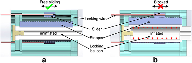
Figure 2. Working principle of the shape-locking module. (a) Locking-off state and (b) locking-on state.
Download figure:
Standard image High-resolution imageRobots in tubular environments should avoid slippage as slippage greatly reduces the efficiency of propulsion [24]. To do so, the robot must maintain effective contact with the inner wall of the tube at all times. However, the diameter of some tubular environments changes constantly; accordingly, this changes the contact status between the robot and the inner wall of the tube. In addition, the contact force in colonoscopy should always be under a threshold value to ensure safety. In this robot, a sensing module is integrated on the periphery of the middle waist link to monitor the contact status. Thus, the robot can be adjusted in real time to avoid slippage and ensure safety. As shown in figure 1(d), the sensing module, which is mounted on the middle waist link, consists of a silicone substrate and a specially designed soft sensor based on the piezoresistive effect. The sensor corresponds to an actuating balloon; therefore, the contact status between the robot and the environment can be monitored when the actuating balloon is driven. The material between the electrodes is pressure-conductive rubber whose resistance can change with the pressure applied to it [25].
2.2. Locomotion principle
To facilitate the analysis of the propulsion module, we simplified its model to a cylindrical body with six actuating balloons and a central cord; the cord and the actuating balloons are fixed together in the body whose role is the same as the backbone. The actuating balloons are spirally distributed around the central cord, and the length between the center of each balloon and the central cord is r. We set the pitch of the spiral balloons to P0. As shown in figure 3(a), when the length of the body is exactly one pitch, the initial length of each balloon L0 is given by the following formula:

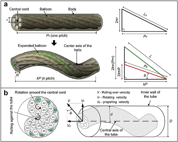
Figure 3. Locomotion principle. (a) Principle of helical deformation and (b) principle of the helical rotating motion.
Download figure:
Standard image High-resolution imageThe length of the central cord is immutable. As shown in figure 3(a), when one of the actuating balloons expands lengthwise, the shape of the body becomes helical, and the corresponding expanded balloon goes onto the outer side of the helical body. P and R represent the pitch and radius of the helical central cord, respectively. When the length of the expanded balloon is L (L ⩾ L0), the helical deformation can be described as follows:
where k is a variable coefficient, which represents the number of turns of the helical body. The helical deformation can be determined when the length of the balloon is given. Hence, a third independent equation is added to provide a unique solution to the system. Generally, the specifics of l(k) are related to the physical characteristics of the propulsion module.
As shown in figure 3(b), the cylindrical model is placed in a tube of appropriate diameter in which the expansion of any balloon can cause the corresponding outer side of the helical body to come into contact with the inner wall of the tube. To illustrate the locomotive principle of the propulsion module, we took a cross-section of the helical body as the analysis object (it is consistent with the whole helical body in motion). When the six balloons (b1 to b6) are alternately expanded and restored in sequence, the cross-section will rotate around the central cord and roll against the tube. The cross-section rolls along a helical line on the tube inner wall rather than in a circle because the rotation axis of the cross-section is at an angle to the central axis of the tube. Hence, the whole helical body can generate a helical rotation that can be separated into a rotation around the central axis of the tube and propulsion along the axis. The velocity relationship between these motions is marked in figure 3(b).
We assume that the outer side of the helical body is in contact with the inner wall of the tube and that there is no slippage between them. If the six balloons are sequentially expanded and restored in period T, the propelling velocity can be expressed as

where d is the diameter of the body and θ is the helical angle of the central cord. According to figure 3(a) and the second equation of equation (2), we obtain
Moreover, there is a relationship,

where D is the diameter of the tube and is equal to the outer diameter of the helical body. From equations (3)–(5), the following equation is obtained:

For a particular prototype whose diameter d is constant, the velocity Vp depends on the control period T, diameter of the tube D, and pitch P. However, when the diameter D is given, the pitch P of the helical body is determined according to (5) and (2), and the propelling velocity is only determined by the control period T.
2.3. Fabrication
A photograph of the fabricated prototype is shown in figure 4(a); it is 195 mm in length and 22 mm in diameter. A charge-coupled device (CCD) camera is mounted on the front end of the prototype. Its electric cable is also used as the central cord mentioned in the previous analysis.

Figure 4. Configuration of the robotic system. (a) Prototype of the developed robot and (b) control system of the robot.
Download figure:
Standard image High-resolution imageThe actuating balloons (5 mm outer diameter, 2 mm inner diameter), locking balloon (6 mm outer diameter, 2 mm inner diameter), and silicone substrate were made of a biocompatible silicone rubber (Smooth-On Dragon Skin™ 20) using a casting method. The fabrication process of the balloons is shown in
The pressure-conductive rubber in the soft sensor is mainly composed of a silicon rubber matrix and graphite nickel-plated fillers. When the pressure applied to the conductive rubber changes, the contact condition of the conductive fillers will change, causing a change in resistance. The dimensions of the conductive rubber are 2 × 3 × 0.5 mm. It was first placed into a groove reserved on the silicone substrate. Then, two electrodes (beryllium copper) were mounted on both sides of the conductive rubber and fixed with the silicone substrate (the electric wires were pre-installed on the electrodes).
2.4. Robotic system configuration
Figure 4(b) shows the configuration of the developed robotic system. In the pneumatic section, pressurized air from an air compressor is first transported to two regulators (FESTO, MS4-LR-1/4-D6-AS), which control the supplied air pressure to the propulsion module and shape-locking module. Then, several two-position, three-way solenoid valves (FESTO, MHE2-MS1H-3/2G-QS-4) are used to achieve independent control of the air supply to each balloon. It can be seen from the robot propulsion principle that the air tubes and cables will become spirally entangled during long-distance propulsion. Therefore, we added a pneumatic–electrical rotatable joint between the solenoid valves and the robot whose output ports can rotate synchronously with the robot. In the electrical section, the cables of the CCD camera and the soft sensor are first connected to the rotatable joint. Then, the soft sensor is connected to a transmitter circuit to convert its resistance into voltage that can be received by the microcontroller (Arduino UNO), and the CCD camera is directly linked to the computer through universal serial bus. To achieve efficient actuation and monitoring of the robot, we established an interface using LabVIEW®. Through the LabVIEW program, we can set the on-off time of the solenoid valves, and the monitoring results of the contact status is displayed in real time. With this system, the robot can be effectively adjusted to actual situations.
Figure 5 shows the given control sequence of the solenoid valves for the propulsion module. In this control pattern, the robot can always maintain a helical formation during propulsion, and the six actuating balloons can be sequentially expanded and restored in period T.

Figure 5. Control pattern of the solenoid valves for the actuating balloons.
Download figure:
Standard image High-resolution image3. Experiments and results
3.1. Locomotion performance
According to the analysis in section 2.2, the propelling velocity Vp of the robot is essentially determined by the control period T and the diameter of the tube D. Therefore, we tested the velocity variation with these two values. To observe locomotion in real time, the experiments were carried out in transparent acrylic tubes (available online at stacks.iop.org/SMS/30/125023/mmedia). Figure 6(a) shows the propulsion process of the robot in a tube at a constant velocity of 5 mm s−1. According to [26], the inner diameter of the intestine is mainly about 25–50 mm. However, if the colon is empty and in a contracted state, which it is during most regular intestine inspections, the lumen is much smaller. In addition, the larger diameter parts are near the cecum, where regular colonoscopies do not always reach. Therefore, the tests were conducted in tubes with diameters of 26–32 mm. We measured the velocity of the robot at a series of control periods, the results of which are presented in figure 6(b). It can be seen from the figure that under the same control period, the propelling velocity increases with an increase in the tube diameter. Notably, the propulsion velocity is inversely proportional to the control period, which is consistent with equation (6).
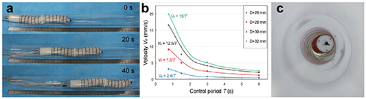
Figure 6. Locomotion velocity of the robot. (a) Propulsion process of the robot in an acrylic tube, (b) velocities under different tube diameters and control periods, and (c) contact status between the robot and acrylic tube.
Download figure:
Standard image High-resolution imageThe relationship between the supply pressure and propelling velocity was also tested, the results of which are shown in table 1. All velocity data are the average of three tests. It can be seen from table 1 that when the supply pressure is not larger than 1.3 bar, the robot cannot propel itself because the outer diameter of its deformed helical shape is still smaller than the tube inner diameter; thus, no effective contact is achieved. For a supply pressure between 1.4 and 1.9 bar, the velocity increases with higher pressure. However, for pressures greater than 1.7 bar, the velocity increase is not obvious. For pressures larger than 2.0 bar, the balloon bursts. Because the velocity increase is not obvious and the balloons are approaching their bursting point at pressures greater than 1.7 bar, the robot was operated at a pressure of 1.6 bar.
Table 1. Relationship between supply pressure and propelling velocity in Φ30 mm tube.
| Pressure (bar) | 0–1.3 | 1.4 | 1.5 | 1.6 | 1.7 | 1.8 | 1.9 | 2.0–∞ |
|---|---|---|---|---|---|---|---|---|
| Velocity (mm s−1) | 0 | 10.46 | 13.42 | 16.67 | 21.26 | 22.21 | 22.25 | Balloon bursts |
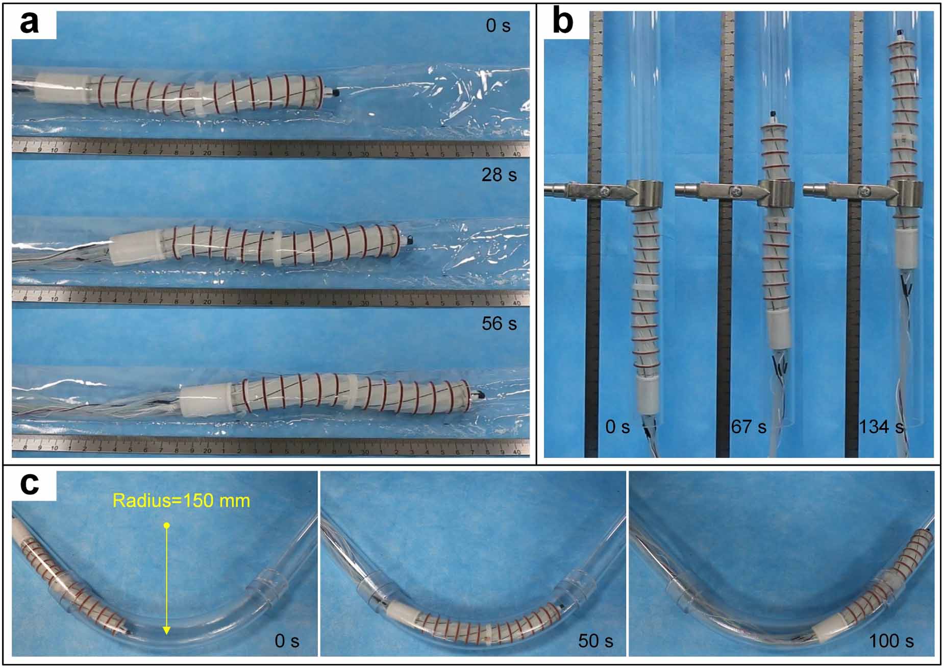
To comprehensively evaluate the locomotion performance, the robot was tested in a flexible tube, vertical tube, and elbow tube (available online at stacks.iop.org/SMS/30/125023/mmedia). Figure 7(a) shows the propulsion process in a flexible tube with a diameter of 30 mm. The robot was able to hold up the flexible tube and advance at a velocity of 1.8 mm s−1 (control period was 3 s). To simulate the environment of a human intestine, the inner wall of the flexible tube was then wetted with water. Under this condition, the propelling velocity fell to 1.4 mm s−1, which is 77.8% of the velocity in the dry flexible tube. Figure 7(b) shows the propulsion process in a vertical tube whose diameter is 26 mm. When the control period was 3 s, the propelling velocity of the robot was 0.8 mm s−1, which is consistent with the results in figure 6(b).

Figure 7. Locomotion performance. (a) Propulsion process of the robot in a flexible tube, (b) process of the robot progressing in a vertical tube, and (c) process of the robot passing an elbow.
Download figure:
Standard image High-resolution imageFigure 7(c) shows the process of the robot passing through an elbow tube at a velocity of 2.4 mm s−1 for which the control period is 1.5 s and the diameter of the elbow tube is 28 mm. More than 50% of the velocity was lost when the robot passed through an elbow tube compared with a straight tube. In addition, the robot can only pass through elbow tubes where the elbow radius is larger than 100 mm. This is because the combination of six balloons and three locking wires by the links reduces the flexibility of the robot body. Further steps must be taken to improve the elbow passing performance, which will be discussed in section 4.
3.2. Contact status monitoring
The piezoresistive characteristics of the soft robot were first tested using the setup shown in figure 8(a), and the results are presented in figure 8(b). We can see that the piezoresistive characteristics of the soft sensor are monotonic, making it suitable for monitoring the contact force. Moreover, the curves of the four measurement cycles are the same, which indicates that the soft sensor works stably. The sensor was integrated in a ring structure (figure 1(d)) with a flat contact surface with the environment (human body). The voltage applied to the sensor is below 1 V, and the corresponding electric current through the sensor is below 10 mA. These features ensure that the sensor is physically and electrically safe for use in the human body.

Figure 8. Performance of the sensing module. (a) A picture of the setup for calibrating the soft sensor, (b) the relationship between force and resistance of the soft sensor, and (c) results of contact status monitoring.
Download figure:
Standard image High-resolution imageTo evaluate the effectiveness of contact status monitoring, we also tested the sensing module when the robot was propelling through a tube (available online at stacks.iop.org/SMS/30/125023/mmedia). As shown in figure 8(c), when the propulsion module was not initially actuated, the contact status signal did not change significantly. At t1, the propulsion module was activated to enable the robot to navigate through the tube. At that time, the contact status signal changed with a period equal to the control period of the propulsion module. When we increased the supplied air pressure at t2, the robot could still advance effectively, but it can be seen from the contact status signal that the contact force had increased. To adjust the robot according to the contact status, we set two contact status thresholds (c1 and c2). When the signal value is lower than the threshold value c1, we deem that the robot does not have effective contact with the inner wall of the tube (inefficient); when the signal value is higher than the threshold value c2, the contact force is deemed too large (unsafe). Two indicator lights were used to visually display changes in the contact status. Through the changes in the indicator lights, we can always adjust the contact status between c1 and c2 (both efficient and safe). Currently, c2 is considered to be 1 N, which is half of the tissue manipulating force [27] and is the safe level of contact force for medical robot work in the gastrointestinal tract; c1 is 0.35 N, which was determined by our experiment trial as the force below which the robot tends to slip.
Tests of the contact force variation for different pressures and tube diameters are shown in figure 9. It can be seen there is an approximately proportional relationship between the pressure and contact force, whereas the contact force decreases linearly with tube diameter.
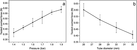
Figure 9. Tested contact force. (a) Contact force variation with pressure in 30 mm tube, (b) contact force variation with tube diameter for constant 1.6 bar pressure.
Download figure:
Standard image High-resolution image3.3. Shape-locking capability
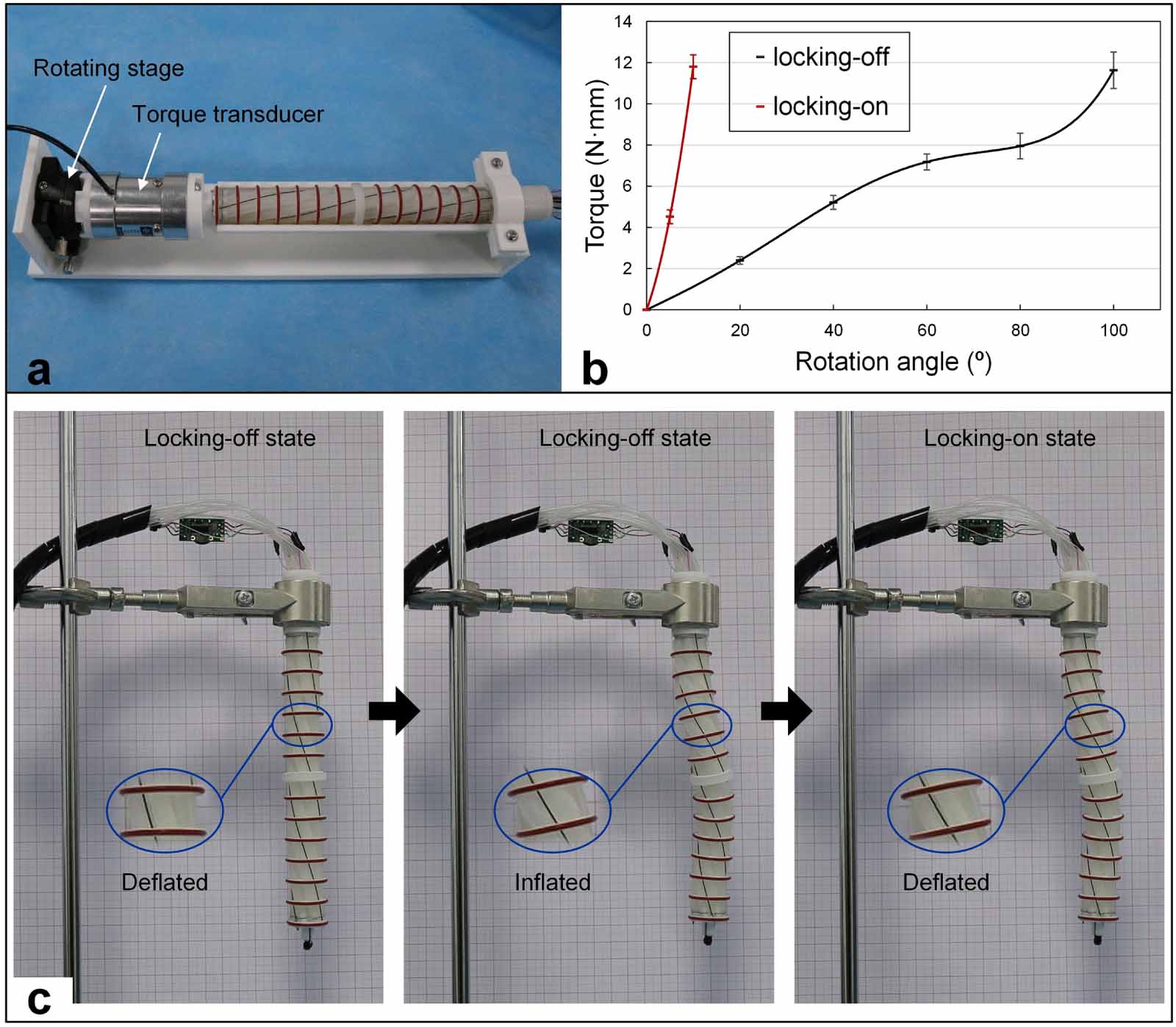
The realization of the shape-locking function essentially depends on the engagement of the stoppers and sliders. To evaluate the engagement effect between them, we measured the torque when the head and tail ends of the robot rotated relative to each other using the setup in figure 10(a).

Figure 10. Performance of the shape locking module. (a) A picture of the setup for evaluating the engagement effect of the stoppers and sliders, (b) the relationship between torque and rotation angle in locking-on and locking-off states, and (c) a demonstration of the shape locking capability.
Download figure:
Standard image High-resolution imageAs shown in figure 10(b), in the locking-on state, when the rotation angle is 10°, the torque can approach an approximate value of 12 Nmm (average stiffness 1.2 N mm/°); in the locking-off state, to obtain this much torque, the rotation angle needs to reach 100° (average stiffness 0.12 N mm/°). Thus, the shape-locking module gives ten times increase in rotating stiffness between the locking-on and off states.
The shape-locking module, in conjunction with the actuating balloons, can lock the shape of the robot in an arbitrary position. To demonstrate this, an evaluation experiment was performed outside the tubes (available online at stacks.iop.org/SMS/30/125023/mmedia). As shown in figure 10(c), the robot was fixed vertically on a clamp. First, two adjacent actuating balloons were inflated, making the shape of the robot helical. Then the locking balloon was inflated, and the actuating balloons were deflated. By comparison, we can see that the helical shape of the robot hardly changed. This result indicates that the shape-locking module is effective in locking the robot.
3.4. Visualization performance
To evaluate the visual quality and integrity during colonoscopy, the robot was tested in an opaque tube with marks on its inner surface (available online at stacks.iop.org/SMS/30/125023/mmedia). Figure 11(a) shows the process of navigating the robot in the tube at a velocity of 3 mm s−1, during which the camera performed a comprehensive inspection of the tube's inner surface. The three views containing the circular marks were taken from the video captured by the camera. Furthermore, as shown in figure 11(b), the robot can be adjusted and maintained in a stable position for the inspection of a target on the tube's inner surface. This task is accomplished by coordinating the shape-locking module with the actuating balloons. By adjusting the actuating balloons, a stable view of any part on the inner surface can be obtained. The results in figure 11(b) are a good validation of the shape-locking capability of the proposed robot.

Figure 11. Inspecting the inner surface of a tube. (a) Time series of the locomotion process and corresponding view from the on-board camera and (b) a stable inspection of a target on the tube's inner surface by co-ordination of the actuating balloons and the shape-locking module.
Download figure:
Standard image High-resolution image4. Discussion
The developed robot performed relatively well in propelling, contact status monitoring, and shape-locking. The experimental results have shown that it has great potential in inspecting the large intestine.
The helical rotating motion of the robot is realized by the actuation of six balloons in sequence. This motion can be generated with only three balloons as well, which is the minimum required number of actuating balloons. Six balloons were used because more balloons can generate more continuous motion, which helps to reduce patients' discomfort. In addition, it ensures that the camera has a relatively stable visual field during propulsion. Moreover, when observing a certain part of the colon's inner surface, more balloons make it easier to adjust the robot to the corresponding position. Furthermore, using six balloons is cost effective, and the structure of the robot is relatively simple. Using more than six balloons will make the fabrication of the robot cumbersome and the structure of the robot complicated.
According to the experimental locomotion performance results, the robot can adapt well to changes in tube diameter within a certain range (26–32 mm). This range is consistent with the average diameter of the distal colon (26 mm for the sigmoid colon and 33 mm for the descending colon), but is smaller than the diameter of the transverse colon (37 mm) and ascending colon (45 mm) [25]. Therefore, this robot is currently only suitable for the distal colon. The propelling velocity corresponding to the shortest control period is 3.2–20 mm s−1. Therefore, the robot can theoretically move from one end of the average human colon to the other (1850 mm [28]) in under 10 min, even at its lowest velocity. Compared with existing flexible endoscopy technology, which entails approximately 30 min for an entire procedure [29], the developed device shows good potential for efficiency improvement. In the propulsion tests, the robot was able to advance in flexible and elbow tubes smoothly, but with some loss in the propelling velocity. This loss can be reduced by decreasing the number of balloons and links or by using more slender locking wires. The propulsion process in the vertical tube indicates that the generated traction of the robot is at least able to overcome its self-weight. This characteristic is a result of the entire helical body of the robot being in contact with the tube during the propulsion process. Moreover, the O-rings arranged on the waist links can generate a large friction force with the tube. To enhance traction in the colon, the O-rings could be covered with a soft polymer film with micro-pillars, whose fabricability and effectiveness in increasing the friction coefficient with intestinal tissue has been confirmed [30].
The sensing module of the robot is arranged on the periphery of the middle waist link as the contact status between this link and environment can reflect the average contact status between the robot and the environment in most cases. According to the experimental results, the monitoring of the contact status is discrete because the contact point changes with the sequential inflation of the actuating balloons and there is only one soft sensor. Nevertheless, the robot was able to sense the contact force with the tubes and work within the effective and safe contact status interval (between two contact-state thresholds) in the experiment, which demonstrates the feasibility of using only one sensor. For colonoscopy, the contact status thresholds c1 and c2 need to be accurately set through clinical tests.
By comparing the relationship between torque and rotation angle in the locking-on and locking-off states, the engagement between the stoppers and sliders was found to be effective. In theory, in the locking-on state, rotation cannot occur when torque increases. The slight rotation is mainly caused by manufacturing errors, which can be ignored depending on the subsequent shape locking experiments (the helical shape of the robot is the same before and after locking). According to the experimental results, for our robot, the shape-locking module has little effect on helical deformation in the locking-off state, whereas the helical formation of the robot can be effectively maintained in the locking-on state. Hence, in coordination with the actuating balloons, the shape-locking module can stably keep the field of view on the target.
To further demonstrate its superiority for use in colonoscopy, some critical properties of the proposed robot were compared with four typical self-propelling colonoscopic devices. The comparative results are summarized in table 2. It can be seen that among all the devices, the worm-like device and our robot are excellent in overall properties. The applicable diameter range of our robot is slightly smaller than that of the worm-like device. However, in terms of velocity and invasiveness, our robot is superior to the worm-like device. Moreover, except for our robot, there is no colonoscopic device which utilizes tactile sensing (perception of contact force).
Table 2. Comparison of self-propelling colonoscopic devices.
| Property | Tracked device [8] | Legged device [12] | Screw-based device [13] | Worm-like device [20] | This work |
|---|---|---|---|---|---|
| Complexity (cost, reliability) | General | High | General | Low | Low |
| Mentioned velocity (mm s−1) | 3 | 0.9 | 2.2 | 12 | 3.2–20 |
| Invasiveness (contact force, flexibility) | Low | High | High | General | Low |
| Diameter adaptability (mm) | — | 30–35 | — | 22–32 | 26–32 |
| Tactile sensing | — | — | — | — | Capable |
5. Conclusion
A novel shape-lockable self-propelling robot with a helical mechanism and tactile sensing for inspecting the large intestine was developed in this study. By sequentially inflating and deflating the six actuating balloons, a helical rotation was realized inside tubes. The robot can be operated in tubes with different diameters (26–32 mm) and is applicable in flexible, vertical, and elbow tubes. Depending on the diameter of the tube, the robot can achieve a propulsion velocity of between 3.2 and 20 mm s−1. Moreover, the capability of the robot to monitor the contact status and the function of the shape locking module were demonstrated by corresponding tests. Overall, the experimental results imply that the proposed robot has high potential for clinical usage in self-propelling inspection of the large intestine.
Limitations of our device include the lack of operating tool and fixed orientation of the camera. In the future, we will develop a specially designed operating tool for the robot, which will achieve more functions in conjunction with the shape-locking module. In addition, if the orientation of the front camera can be adjusted remotely, the screening quality will be further improved. An electrical skin using more soft sensors will be explored and employed instead of the single sensor in this work to monitor the contact status between the entire body of the robot and the colon.
Acknowledgments
This work was supported in part by the National Key R&D Program of China under Grant No. 2019YFB1311501 and in part by the National Natural Science Foundation of China under Grant Nos. 62133010 and 61773280.
Data availability statement
The data generated and/or analysed during the current study are not publicly available for legal/ethical reasons but are available from the corresponding author on reasonable request.
Conflict of interest
No competing financial interests exist.
: Appendix
The fabrication process of the balloons is shown in the following figure. First, the two parts of the silicone rubber are mixed together in equal proportions. Second, a vacuum machine is used to remove all air from the mixture. Molds (purple in the figure) were designed using CAD software and fabricated by 3D printing. A metal rod is used to create the cavity of the balloon. Thirdly, the mixture is poured into the mold and the air removal process is conducted again. Because the balloon has thin walls compared with its length, the cavities between the mold and the metal rod are narrow. A syringe can be of great help in this process to inject the mixture into the cavities uniformly. After injection and combining the two halves of the molds, it is recommended that the assembly be shaken to avoid big bubbles. Finally, after the silicone is set, the balloon can be demolded. Because the silicone rubber balloon is elastic and is partly glued to the molds and the metal bar, it can be easily broken in the demolding process. Unfolding the molds first is recommended, during which the separation between the tube and the mold should be carefully observed. A 'massage' process is strongly recommended before separating the balloon from the metal bar.

Download figure:
Standard image High-resolution image