

Abstract
Auxetic and negative thermal expansion metamaterials have a wide range of applications in flexible electronics, aerospace, biomedicine. Based on the compression/thermal–torsion coupling effects, and combining the special deformation mechanism of the planar anti-tetrachiral structure, this work proposed a novel 3D mechanical metamaterial with negative Poisson's ratio (PR) and negative coefficient of thermal expansion. The mechanical design method of the metamaterial is demonstrated, and the coordinated deformation theory between its in-plane and out-of-plane deformations is established. By numerical simulation, the torsional deformation response of torsion unit of the metamaterials is explored, and Poisson's characteristics and thermal expansion effect of the metamaterials are analyzed. The results show that the PR and thermal expansion effect of the metamaterial can be adjusted and switched, and its deformation behavior can be programmed. The coupling design method for metamaterials provides a good design strategy for engineering applications such as intelligent actuators, flexible robots, and biomedical sensors.
Export citation and abstract BibTeX RIS
1. Introduction
Mechanical metamaterials have exhibited novel characteristics and functions [1, 2] due to their unique microscopic lattice structure design and diversified topological parameters. Among them, auxetic metamaterials [3] which are also called negative Poisson's ratio (PR) metamaterials are one of the most interesting sub-families. When subjected to axial tensile load, they exhibit abnormal behavior of expansion in the transverse direction. With such behaviors, they are shown to provide some enhancements in mechanical properties, such as energy absorption [4–7], indentation resistance [8] under impact load, and negative thermal expansion, etc. Auxetic metamaterials have been designed to meet the needs of different industrial fields, such as the aerospace field of deformable wings [9], the biomedical field of stent [10, 11], the flexible electronic field of flexible electronic skin [12–14] and flexible sensors [15, 16], etc.
Based on these potential application prospects, scholars have been interested in the research of auxetic metamaterials. Adjusting the material properties by designing the configuration, topology, size and arrangement of the unit cell provides a new method for designing metamaterials. A large number of unit cell structures (such as concave honeycomb [17–22], rotating polygon [10, 22, 23], lattice [24, 25], origami [26, 27], etc) have appeared, and the tunability of mechanical properties has been fully proved theoretically and experimentally [28–30]. Similar to the negative PR, the materials with zero or even negative coefficient of thermal expansion (CTE) [31, 32] are also widely favored by scholars. The current main design idea is to carefully design the composite microstructure, by using two materials with positive CTE to generate thermal expansion mismatch to achieve negative thermal expansion effect. Typical microstructures include stretch-dominated bi-material triangles [33, 34] and some derived spatial polygons (such as triangular pyramids, quadrangular pyramids, etc [35, 36]) and bend-dominated chiral structures [37]. In addition, some structures that realize the coupling of negative thermal expansion and negative PR [38–40], which provides the feasibility of multi-field control structures with both temperature and mechanical sensitivity.
In recent years, the chiral structure that exists widely in nature has become the focus of research. It has been used in the development of auxetic metamaterials [41, 42], negative thermal expansion metamaterials [37, 43], and also involved in compression-twisting materials. Since 2017, a paper using stacks of chiral structures without mirror symmetry has officially revealed a class of metamaterials that twist with compression [44]. Inspired by this, various mechanical metamaterials based on tilted rod chiral mechanisms [45–49] have been developed. Many compression-torsion coupling structures have been designed and studied, but no scholars have studied structures with thermal-torsion coupling effect, nor have they applied the thermal-torsion coupling effect to the development of negative thermal expansion metamaterials. The thermal-torsion coupling effect is similar to the compression-torsion coupling effect. When the structure is stimulated by temperature changes, the thermal expansion deformation will be converted into twisting deformation.
Therefore, different from the previously studied 3D structure, based on the compression/thermal–torsion coupling effects, and combining the special deformation of the chiral structure, a novel 3D metamaterial with negative PR and negative CTE is proposed in this paper. First, the mechanical design method is explained in detail; then, the deformation theory of metamaterials is derived; some details and necessary explanations of numerical simulation are explained. Secondly, the results of numerical simulation and theoretical analysis are compared, and the factors affecting the expansion characteristics (i.e. Poisson's characteristics and thermal expansion effect) of the 3D metamaterial are discussed. Finally, some important conclusions and prospects are provided.
2. The auxetic layer design
2.1. Mechanism of tailorable PR and CTE for the bi-material auxetic layer
This paper introduces a novel 3D lattice metamaterial, which is based on the design methods of compression-torsion and thermal-torsion coupling with planar chiral cell structure respectively, which can achieve negative PR under axial load and negative thermal expansion under the stimulation of temperature change of the external environment.
Figure 1 shows the configuration design and deformation model of the novel auxetic metamaterial. The metamaterial is composed of a planar anti-tetrachiral structure and torsion units connected by nodes. The planar anti-tetrachiral structure is called lattice layer. The lattice layers are connected by torsion units. The torsion unit is obtained by an array of the Z-type composite beam and bending, and the lattice layer and the torsion unit together are called the auxetic layer. It is assumed that the auxetic layer is in the infinite model to eliminate boundary effects. The metamaterial is obtained through a periodic array of auxetic layers, so the auxetic layer is taken as the representative analysis unit of the metamaterial, and periodic boundary conditions are applied in the numerical simulation. The auxetic layer is composed of Aluminum and Invar. Among them, the horizontal beam of the Z-type composite beam is given Aluminum (red), and the remaining components are given Invar (green). The properties of the component materials are shown in table 1. Through this bi-material design, the composite metamaterials can achieve customizable PR and CTE.

Figure 1. The configuration design method of the metamaterial.
Download figure:
Standard image High-resolution imageTable 1. Elastic modulus, Poisson's ratio and thermal expansion coefficient of Aluminum and Invar.
| Components | Elastic modulus (GPa) | Poisson's ratio | CTE |
|---|---|---|---|
| Aluminum | 70.7 | 0.33 | 2.32e-5 |
| Invar | 144 | 0.29 | 1.2e-6 |
The deformation mechanism of the metamaterial is as follows. Due to the asymmetric chiral composite beam design, when an axial load is applied to the metamaterials, the Z-type composite beam will drive the top circle and bottom circle of the torsion unit to rotate in opposite directions while reducing the axial out-of-plane distance. When the top circle and bottom circle rotate, due to the special configuration of the chiral structure, when the direction of the ligament is in the reasonable direction of the two circles, the corresponding nodes in the adjacent lattice layer always have the opposite direction of rotation (that is, adjacent lattice layers are perpendicular to each other), the lattice layer can achieve in-plane contraction. In the same way, when a temperature change stimulation of a certain amplitude is given, the three-way shrinkage of the metamaterial can also be achieved due to the mismatched deformation of the thermal expansion of the two-component material. It is worth noting that because the ligaments are connected to the top circle and bottom circle of the cylinder and are in the tangential direction, it is reasonable that the connection point between the ligament and the circle is in any position.
It can be found that the most fundamental deformation mechanism of the metamaterial with expansion characteristics is the torsion effect of the torsion unit. In order to better explore the expansion characteristics of the metamaterial, it is very necessary to quantitatively characterize the torsion characteristics of the torsion unit and the superposition effect and mechanical properties of the metamaterials in the axial extension process. Therefore, in section 3.1, considering the observability of deformation, the ease of convergence of structural simulation and the efficiency of calculation, we expand the torsion unit to 5 layers along the z-direction, so as to assemble in series into five-layer series torsion unit (FSTU) with different performances and perform numerical simulations to verify the assumption.
2.2. Deformation analysis and theory
In this section, the deformation relationship between the plane anti-tetrachiral structure and the torsion unit in the metamaterial are introduced. We selected a representative auxetic layer as the theoretical analysis model of the metamaterial. As shown in figure 1, the auxetic layer is composed of anti-tetrachiral lattice layers and torsion units, and the metamaterial is formed by periodic arrays of auxetic layer. As shown in figures 2(a) and (c), the geometric parameters of the analysis model are the circumferential radius r (set r = 10 mm)of the torsion unit, the height a of the Z-type composite beam, which is the partial plane unfolding model of torsional unit (figure 2(a)), the length l of the inclined beam, the length c of the horizontal beam, and the angle  between the inclined beam and the horizontal beam, the length of the ligament is 2d (i.e. center to center distance of circular element), the cross-section of the ligament is a rectangle with length h and width b (both h and b are much smaller than a, set h = 1 mm, b = 0.25 mm), and the remaining cross-sections are squares with side length t = 1 mm. At the same time, based on previous studies, assuming that the circle is a rigid body, it maintains its original shape during structural deformation [50], which only serves as a connection and transfer force. Under uniaxial compression, the deformation of each ligament is antisymmetric with its midpoint, so there is no bending moment at the midpoint of the ligament, and the midpoint of the ligament is always located on the line of the center of the adjacent rings of the lattice layer. For small deformation models, the torsion unit can be simplified to a plane stress state.
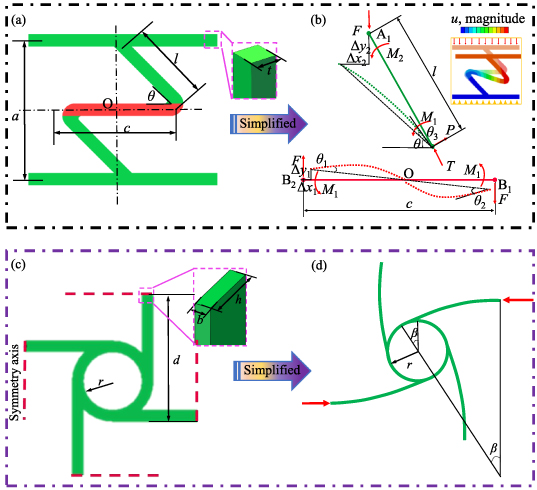
Figure 2. Theoretical analysis models (a) and (c) of the metamaterial and its simplified analysis models (b) and (d).
Download figure:
Standard image High-resolution imageFigures 2(b) and (d) are the simplified analysis models of torsion unit and anti-tetrachiral lattice layer, respectively. The illustration in figure 2(b) shows the deformation mode of the Z-typed composite beam under compression load. Where F corresponds to the vertical downward normal force of the lattice layer on the inclined beam, the reaction force of the horizontal beam on the inclined beam is decomposed into the normal force T and the shear force P,  is the concentrated force couple of the inclined beam to the horizontal beam,
  is the concentrated force couple of the lattice layer to the inclined beam. Suppose the upper endpoints of the inclined beam is A1, the left and right ends of the horizontal beam are B1, B2 respectively.
The force components of the simplified structure are shown in figure 2(b) upon the decomposition of the structure. The relationships between these force components are:


From the moment balance condition of the Z-shaped composite beam, we can find:
From the moment balance condition of the inclined beam, we can find:

From the moment balance condition of the horizontal beam, we can find:

Simultaneous equations (4)–(6) yields:
The θ1, θ2 and θ3 shown in figure 1(c) are the maximum deflection angles of the horizontal and inclined beams respectively, where θ1, θ2 are equal under these conditions. From Timoshenko beam theory, the angle of deflection of the horizontal beam θ' could be expressed as:
where  , ω is the deflection of the horizontal beam and γ is the shear strain, G1 is the shear modulus, E1 is the elastic modulus. Owing to the cross section of the beam is a square, the second moment of inertia of the cross section
  , the cross-sectional area A = t2, the geometrical factor κ = 5/6.
Coupling the result that θ1 = θ2 with equation (9), the maximum deflection angle could be expressed as [51]:
Similarly,
where E2 is the elastic modulus of the inclined beam, G2 is the shear modulus.
Substituting equations (2), (7), (8) in equations (10), (11) leads to:
It is assumed that the connection point between Aluminum and Invar is rigid, so the concave angle remains unchanged before and after deformation. According to the method of Onck et al [51], the displacement of points B1 and B2 along the x- and y-directions relative to point O caused by horizontal beam deflection can be expressed as follows:


Similarly, the displacement of points A1 along the x- and y-directions relative to point B1 caused by the inclined beam deflection can be expressed as follows:


Simultaneous equations (12)–(17), the displacement of points A1 along the x- and y-directions relative to point O can be expressed as follows:
Within the range of elastic deformation, the relationship between the shear modulus G, elastic modulus E, and PR  of isotropic material is:
 ,
,  , where
  and
and  are the PR of the horizontal and inclined beams respectively.
For simplicity, an arc deformed shape is assumed for the ligaments, the torsional response is only relative to the deflection of the ligament in order to obtain the relationship between the in-plane strain  of the lattice layer and the torsion angle [52].
where β is the model rotation.
Since the Z-typed composite beam is centrosymmetric, the displacement of point A1 relative to point O should be equal to the arc length of the node circle:

The PR of the metamaterial in the z-direction can be given as:
Simultaneous equations (21)–(23) leads to:
Substituting equations (18), (19) in equations (24), (24) can be further expressed as:
For the materials selected in this paper (table 1),  is much smaller than
  , and
, and  is much smaller than
  , which can be ignored. Therefore, equation (25) can be simplified to:
Equation (26) shows that the PR is affected by geometric parameters  and θ. The value of
  actually represents the aspect ratio of the auxetic layer. Fixed the θ, when
  is particularly small, it indicates that the in-plane span of the auxetic layer is large, but the out-of-plane thickness is small, the negative PR effect is small at this time. In order to explore the validity of this theoretical analysis, a numerical simulation method was carried out, comparisons and evaluations will be made in the following sections.
2.3. Parametric design and numerical simulation method
In order to systematically explore the designability and corresponding mechanical behavior of the metamaterial proposed in this paper, parametric studies are carried out. The 3D CAD models of the metamaterial are designed in the software SolidWorks 2020, and presented in figure 3. Besides, the numerical simulations are conducted through the software Abaqus 6.14. After the sensitivity analysis on the influence of the geometrical parameters of the structure, in the parameterization study, we focused on three important dimensionless parameters  ,
,  ,
,  and
and  , quantified the influence of each parameter on the torsion angle (
 ) of the FSTU, as well as the PR (
 ) and CTE (
 ,
,  ) of the metamaterial. Due to the symmetry of the structure,
  =
=  . The
. The  and
and  represent the CTEs of the metamaterial in the plane (x/y-direction) and out of the plane (z-direction), respectively. Specifically, as shown in figure 3(a), keep
  =
=  unchanged, and take
  ,
,  respectively with 0.2 as the interval, there are 16 kinds of models. As shown in figure 3(b), keep
  ,
,  unchanged, take
  =
=  ,
,  ,
,  ,
,  respectively, there are 4 kinds of models. Therefore, a total of 20 different parametric models have been established for the FSTU. In addition, we also choose
  = 1.5 and 2.0 respectively to explore the influence of the length of the chiral ligament on the metamaterial. Therefore, a total of 40 different numerical simulations are carried out for the parametric study of the metamaterial.

Figure 3. (a), (b) 3D CAD models of torsion unit under different geometric parameters; (c) the finite element models of the FSTU (left), metamaterials (right) and their partially enlarged view.
Download figure:
Standard image High-resolution imageThe finite element model uses C3D8R elements, where the size of the grid (0.25 mm) is small enough to ensure the convergence and accuracy of the numerical results, and the interface between the two materials is a bound connection. Assuming that the composite beam is sufficiently slender, a linear elastic small deformation model is adopted, and the effect of axial compression and shear in the overall deformation of the structure is ignored. Besides, in the interest to eliminate boundary effects and obtain the intrinsic mechanical properties of the metamaterial, similar to the work of Ebrahimi et al [52], the auxetic layer with periodic boundary conditions is applied in numerical simulation to simulate the infinite metamaterial model and the infinite metamaterial model has good compatibility with the deformation of the auxetic layer. The numerical simulation is divided into two parts: the compression-torsional deformation response of the FSTU and the expansion characteristics of the metamaterial. The finite element model of compression-torsional deformation response of FSTU is shown in figure 3(c-left). The six degrees of freedom on the surface of the six lattice layers of the FSTU are coupled with RP-0–RP-5 to output the torsion angle of each layer. Then apply rotation constraint and displacement load uz to RP-0, and apply displacement constraint (uz =0) to RP-5 in the z-direction (the layer where RP-0 is located is called layer 0, and so on, the layer where RP-5 is located is called layer 5). The finite element model of the metamaterial is shown in figure 3(c-right), the nodes on the right boundary (red region) and the front boundary (blue region)of the ligament are coupled to move freely in x- and y-directions respectively, the nodes the left boundary (black region) and on the back boundary (orange region) of the ligament are restricted by the freedom of movement in the x-direction (ux = 0) and y-direction (uy = 0) respectively, the bottom surface is constrained to move the degree of freedom in the z-direction (uz = 0). When analyzing the negative PR behavior of the metamaterial, a compression displacement load is applied in the z-direction; when analyzing the negative thermal expansion behavior, the initial ambient temperature is set to 25 °C, and the maximum thermal load of the metamaterial is 225 °C, which is equivalent to Temperature change of 200 °C.
3. Results and discussion
3.1. Research on torsion characteristics of the FSTU
In the interest to reveal the twisting deformation mechanism of the chiral torsion unit, we performed a numerical simulation on the FSTU. There are many torsion units listed in figure 3. If all the numerical simulations are carried out, the time cost is very high. Therefore, we selected the FSTU under the four sets of geometric parameters in figure 3(b) to explore their torsion characteristics. Figure 4 shows the stress and displacement contours of the FSTU with geometric parameters  ,
,  ,
,  under a displacement load of about −5 mm (9% strain) in the z-direction, and different degrees of twisting in different lattice layers. Because it is connected in series in an array, the torsion effect of each layer will be superimposed on each other. Obviously, the place with larger stress appears at the corner of the Z-type composite beam. The possible reason is that there is a small included angle here, which is prone to stress concentration. On the other hand, it is the connection point between Aluminum and Invar, and the stress will be relatively large. Through the multi-layer series connection of the torsion angle superimposition effect, we can clearly observe that as the axial compression (tension) displacement increases, the torsion angle of the FSTU in the clockwise (counterclockwise) direction around the z-axis gradually increases (the inclination of the black dotted line in figure 4 indicates the torsion angle of the FSTU), and the largest torsional deformation occurs at the bottom end of the FSTU.
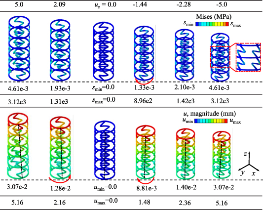
Figure 4. Compression-torsion deformation response of the FSTU with  ,
,  ,
,  at uz
= 5.16 mm, 2.16 mm, 0 mm, −1.66 mm, −2.51 mm, −5.0 mm respectively: (a) stress contours and (b) displacement contours.
at uz
= 5.16 mm, 2.16 mm, 0 mm, −1.66 mm, −2.51 mm, −5.0 mm respectively: (a) stress contours and (b) displacement contours.
Download figure:
Standard image High-resolution imageIt can be seen from figure 5(a) that the displacement-torsion angle change curve of the FSTU in tension and compression is symmetrical about the initial position. The torsion angle increases linearly with the axial displacement. It is worth noting that the slope of the black line in figure 5(a) is negative, indicating that under the same mechanical design assembly mode and load, the corresponding the FSTU has the opposite twisting direction compared to the others. The two-way torsion behavior of the FSTU allows the design of multifunctional lightweight structures or actuators. In addition, in order to explore the superimposition effect of the torsion characteristics of the torsion unit, we exported the correspondence relationship (figure 5(b)) between the torsion angle and the displacement uz of the coupling reference points RP-1–RP-5 (figure 3(c)) of the finite element models in figure 3(b) from software Abaqus.
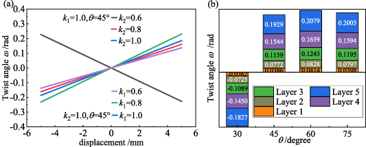
Figure 5. (a) Displacement-torsion angle curves of the FSTU and (b) histogram of twist angle of the lattice layer of the FSTU.
Download figure:
Standard image High-resolution image3.2. The influence of geometric parameters on the CTE and PR of the metamaterial
In section 3.1, we have mastered the torsion deformation mechanism of the torsion unit. The torsion angle increases linearly with the increase of the number of superimposed layers. Therefore, the proposed joint design has a wide joint rotation range, which can realize the flexibility of torsion and axial contraction. Adjust the coupling design, and further realize the adjustable coupling design of torsion and axial contraction, and can further realize the expansion of the 2D planar anti-tetrachiral structure to 3D to form a 3D honeycomb structure. Through the intermediate bridging action of the torsion unit, the relationship between the deformation in the xoy plane and the deformation out of the plane (z-direction) can be established. In the following sections 3.2.1 and 3.2.2, 40 types of auxetic layers (figure 3 (c-right)) composed of planar anti-tetrachiral structures with ligament lengths of d = 15 mm ( ) and d = 20 mm (
 ) combined with the 20 torsion units as the analysis objects. And the influence of geometric parameters on the PR and CTE of the metamaterial is explored. The results of the numerical simulation are shown in figure 6.

Figure 6. CTEs and PRs of the metamaterial under different geometric parameters (unit of CTE: ppm per °C).
Download figure:
Standard image High-resolution image3.2.1. Research on the influence of geometric parameters on PR of the metamaterial.
In this section, numerical simulation is used to explore the PR of the metamaterial composed of auxetic layers with a single torsion unit. Figure 7 shows the displacement contours of the auxetic layer under compressive displacement load (5% strain) in the z-direction, which is the same as the expected deformation law, the metamaterial shrinks uniformly along the three directions of x, y, z. Within the error range, the shrinkage displacements in the x- and y-directions can be considered equal, and these errors may be caused by the asymmetry of the meshing of the finite element model.

Figure 7. Displacement contours of auxetic layer with geometric parameters  ,
,  ,
,  ,
,  under compressive displacement load (5% strain) in the z-direction. Scaling factor = 4.
Download figure:
Standard image High-resolution imageFigure 8 shows the effect of geometric parameters on PR. Figures 8(a) and (b) provides the contours of the effective PR of the metamaterial with  when
when  equal to 1.5 and 2.0 respectively, indicating the impact of
  and
and  on the effective PR. Clearly, the PRs of the metamaterial near the diagonal (i.e.
  =
=  ) are relatively small, and the closer to the lower right corner, the greater the PR. Figure 8(c) is the difference of PRs of the metamaterial when
  is equal to 1.5 and 2.0, namely
  . It is not difficult to see that,
  , this indicates that the increase of
  will weaken the positive and negative PR effects of the metamaterial, which is also confirmed in figure 8(d). Figure 8(d) shows the change curve of PR in the row or column where the arrow symbol is located, and each arrow symbol represents the PR value of the row or column where it is located. Besides, figure 8(e) shows the comparison between the results of the numerical simulation and the theoretical analysis, for the model fixed
  , keep
  =
=  = 1.0 unchanged, with the increase of
  , the PR gradually decreases from positive to negative. It can be found that in figures 8(d) and (e), when k1< 0.6 or
  =
=  , the PR is positive, which can be confirmed in figures 5(a) and (b). The finite element models represented by the black line in figure 5(a) and the first column of data in figure 5(b) have a torsion angle opposite to other models under compressive load. According to the design mechanism of coupling mechanics, it can be known that the lattice layer will expand rather than contract in the xoy plane, so the PR is positive. It is worth noting that when θ increases from
  to
to  and then increases to
  , PR gradually decreases, but when θ continues to increase to
  , PR increases abnormally, which is mutually confirmed by figure 5(b). In figure 5(b), when the θ angle increases to
  , the torsion angle decreases abnormally, resulting in a decrease in the shrinkage displacement of the lattice layer in the xoy plane, and the negative PR effect will decrease.

Figure 8. The effect of geometric parameters on the PR of the metamaterial. (a), (b) Distribution of the PR of determination over a range of geometrical parameters ( ,
,  and
and  ). (c) The distribution of the difference between
  and
and  . (d) Numerical simulation results of PR of the versus the geometrical parameters (
 ,
,  and
and  ). (e) Numerical simulation results of PR of the versus the geometrical parameter
  .
.
Download figure:
Standard image High-resolution image3.2.2. Research on the influence of geometric parameters on the CTE of the metamaterial.
Figures 9 and 10 respectively show the distribution law of the CTE of the metamaterial under the stimulation of a temperature change of 200 °C. Figures 9(a) and (b) provides the contours of the effective CTE of the metamaterial with  ,
,  , indicating the impact of
  and
and  on the normalized effective CTE. It can be seen from figures 9(a) and (b) that the closer to the upper left corner (that is, the smaller
  , the larger
  ) and the smaller the
  and
and  , the more obvious the negative thermal expansion effect of the metamaterial; on the contrary, the closer to the lower right corner (that is, the larger
  , the smaller
  ), the larger the
  and
and  , the weaker the negative thermal expansion effect of the lattice. This can be verified from the variation curve of the CTE of the metamaterial under some geometric parameters shown in figure 9(c). The minimum value of
  reaches −12.2 ppm per °C, and the minimum value of
  reaches −4.87 ppm per °C. The results of the numerical simulation also show that the anisotropic the metamaterial can be obtained through reasonable geometric parameter design. As shown in figure 9(d),
  of the metamaterial of the row where the black arrow is located is less than 0, but
  greater than 0. This provides a good idea for the design of anisotropic materials. Besides, it can be clearly seen from figure 9(e), keep
  =
=  = 1.0 unchanged, and with the increase of
  , both
  and
and  gradually decrease from positive until it becomes negative.
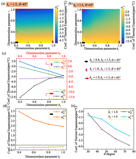
Figure 9. The effect of geometric parameters on the CTE of the metamaterial with  . (a), (b) Distribution of the CTE of determination over a range of geometrical parameters (
 and
and  ). (c), (d) Numerical simulation results of CTE of the versus the geometrical parameters (
 and
and  ). (e) Numerical simulation results of CTE of the versus the geometrical parameter
  .
.
Download figure:
Standard image High-resolution image
Figure 10. The effect of geometric parameters on the CTE of metamaterials with  . (a) The distribution of the difference between
  and
and  . (b) Distribution of the CTE (
 ) of determination over a range of geometrical parameters (
 and
and  ). (c), (d) Numerical simulation results of CTE of the versus the geometrical parameters (
 and
and  ). (e) Numerical simulation results of CTE of the versus the geometrical parameter
  .
.
Download figure:
Standard image High-resolution imageFigure 10(a) provides the contour of the difference of the effective CTEs of the metamaterial with  and
and  , namely
  . Obviously, within the error range, it is considered to be almost zero. This means that the change of
  will only change the in-plane CTE but not the out-of-plane CTE. This can be verified by comparing figures 9(c) and 9(e), 10(c), and 10(d) respectively. The curves with the same color indicate that the metamaterial has the same torsion unit but different ligament lengths of the lattice layer. Therefore, we can draw the conclusion that the ligament length coefficient
  only affects the expansion and contraction of the planar anti-tetrachiral lattice layer, and the
  ,
,  only affects the rotation and longitudinal expansion and contraction of the torsion unit. The effect of the two on the deformation is mutually independent. This provides a new idea for the design of anisotropically adjustable metamaterials, that is, if you need to increase the negative thermal expansion effect of the metamaterial in the z-direction, you need to adjust the parameters
  ,
,  ,
,  of the torsion unit instead of the ligament length coefficient
  . On the contrary, if you need to increase the negative thermal expansion effect in the xoy plane, you need to adjust the ligament length parameter instead of the torsion unit parameter.
Section 3.1 discusses the series superposition effect of torsion units and verifies that the torsion angle can be superimposed in series by torsion units. Section 3.2 discusses the influence of geometric parameters on the PR and CTE of the metamaterial, which shows the deformation independence of the plane anti-tetrachiral lattice layer and the torsion unit. Therefore, it is conceivable that when multiple torsion units are connected in series in an array, the auxetic layer can superimpose the torsion generated by each torsion unit, which will contribute to the large torsion and large shrinkage of the overall structure, and enhance the negative PR and negative thermal expansion effects of the metamaterial. Figure 11(a) shows the auxetic layer with two torsion units and (b) three torsion units connected in series. In addition, the metamaterial is assumed to be in a uniform temperature field, that is, every position of the metamaterial is simultaneously stimulated by the same temperature. However, if it is stimulated by non-uniform temperature, the metamaterial may produce higher thermal stress and self-locking phenomenon at the cell junction. These conjectures will continue to be verified in subsequent work.

Figure 11. Auxetic layers with (a) two and (b) three torsion units in series.
Download figure:
Standard image High-resolution image4. Conclusion
This paper proposes a novel 3D mechanical metamaterial with negative PR and negative CTE based on chiral mechanism. An analytical formula for the coupling deformation between the anti-tetrachiral structure and the torsion unit is deduced. The numerical results show that the metamaterial can realize the auxetic effect in 3D space and verified the analytical predictions well. The metamaterial can not only achieve negative PR through compression-torsion coupling but also achieve negative thermal expansion through thermal-torsion coupling.
Conclusions are summarized as follows:
- (a)The compression-torsion response of the FSTU has a linear superposition effect, and the torsion angle increases linearly with the increase of the number of superimposed layers.
- (b)The change of geometric parameters can realize customized adjustment of PR and CTE.
- (c)The telescopic deformation of the planar anti-tetrachiral lattice layer and the torsional deformation of the torsion unit are independent, so we can control and adjust
 and of the metamaterial individually. Combining the compression-torsion superimposition effect of the FSTU further will help the large torsion and large contraction of the metamaterial, and enhance the negative Poisson's ratio and negative thermal expansion effects of the metamaterial.


Acknowledgments
This work was supported by the National Natural Science Foundation of China (Project Nos. 11932002, 11802166 and 11902032), which is gratefully acknowledged.
Data availability statement
All data that support the findings of this study are included within the article (and any supplementary files).