
Abstract
A piezoelectric device connected to the standard interface circuit is proposed for harvesting energy by inducing the mixed resonant modes of vibration under the two-point rotary magnetic plucking. It consists of a piezoelectric cantilever beam attached to a tip magnet and a second magnet placed on the middle of the beam. Both magnets are excited by another two magnets aligned radically and attached to a rotating host. The two impulsive forces from these magnets are made in opposite directions for the ease of inducing the second resonant mode. As a result, the harvester device exhibits the pronounced broadband energy harvesting which can not be achieved by the conventional design based on the one-point magnetic plucking for exciting a single resonant mode. The analysis is based on the Fourier decomposition of magnetic impulsive forces for realizing the phenomenon of frequency up-conversion. In addition, the estimate of harvested power is analytically derived based on using the equivalent load impedance which is originally proposed for analyzing harvester arrays. The result shows that the theoretical prediction agrees well with the experimental observation. Further, the rotary frequency response exhibits the remarkable feature of broadband energy harvesting as the output power is increased up to 2500% higher than that in the off-resonance region of the setup allowing plucking only on the tip magnet.
Export citation and abstract BibTeX RIS
1. Introduction
Due to escalating demands of the smart sensor device, the electrical energy consumption is essentially required and becomes an increasing visibility in the microsystem technology markets. It is known that the power supply of battery only gives a limited energy source during system operation. As a result, this leads to the time-consuming task for its replacement, which is normally located at the remote area. It then inevitably affects the effectiveness of device usage. To assuage such condition, micro-power harvesting, as a viable alternative engineering solution, can be designed and enables to convert the energy harvesting using a surrounding vibration environment. Such technique has been reported by numerous researchers over the past decade. One of the profound technical capabilities can be found in the use of a smart structure with embedded piezoelectric material. The complete production of the piezoelectric harvesting obviously underlies on the three principles of technical knowledge such as geometry and material properties, fabrications, and power electronic circuits [1, 2].
Nevertheless, the motivation for investigating various models of the piezoelectric vibration-based power harvesting has risen important aspect, particularly for analyzing the electromechanical dynamic system behavior. Starting with the lumped electromechanical parameter models [3], the circuit techniques with various case studies have been developed using the resistive load impedance [4], AC-DC harvesting circuit [5], the synchronized switching harvesting on an inductor (SSHI) [6–8] and the synchronized electric charge extraction (SECE) [9, 10]. Another work focusing on the continuous vibration modeling with the piezoelectric beam [1, 11–14] and plate [15–17] structures has also been developed by considering various mechanical systems and electrical network strategies. Using the multimodal system level of beam arrays, the appearance of multiple resonance peaks can be achieved by using different dimensions of the structures and by tuning further their magnitudes using circuit interface with the SSHI/SECE system [18–24]. Another alternative way for widening the two-resonance of power output using the nonhomogeneous and discontinuous piezoelectric beam has been investigated using a shunt control [11]. Moreover, tuning the resonances at the higher modes of operations and boosting the optimal power output of the piezoelectric plate structure [16] has been developed using an electrical network of the multiple electrode segments. Finally, the multimodal energy harvesting for broadband improvement can also be achieved by designing specific structures with multiple close peaks of resonances [25]. These include the works of L-shape/meandering beam [26–28], multi-degree-of-freedom energy harvesters [29–32], mixed modes of bending and torsion [33, 34], and the harvester beam with a multimodal dynamic magnifier [35].
As clearly seen in the aforementioned literatures, vast majority of the studies for bandwidth improvement, such as array, multimodal and resonance tuning techniques, have been still built on the axial motion excited at around the device's resonances. Therefore, harvesting vibration energy at low excitation frequency is indeed a challenging task for small size of harvesters. A technique for alleviating such condition is to develop frequency up-conversion energy harvesters [36]. This method is to induce a higher-frequency resonance in a transducer from a smaller-frequency motion of ambient source. Therefore, it permits a resonant harvester to operate in a non-resonant practice [37]. Two common strategies for enabling frequency-up include the impact [38–40] and plucking mechanisms [41–43]. The former typically implemented by introducing a stopper to limit the amplitude, can broaden bandwidth and harvest more power because of the larger bandwidth [44–46]. The latter is useful when the energy availability is high and is operated by two different implementations. One is the mechanical plucking transferring energy from the plectrum to the harvester device [47–50]. The other is the magnetic plucking capable of creating a contactless energy transfer due to a reciprocating excitation [51–55]. Each of them has its own useful advantages in specific environments, and some of them have shown success in certain applications. For example, the use of magnetic/piezoelectric frequency-up conversion has recently exhibited significant improvements in wrist-worn energy harvesting applied to self-powered smart watches or wristbands [56–58].
The article is focused on the study of rotary magnetic plucking using the piezoelectric transduction. The conventional design consists of a piezoelectric cantilever beam with a tip magnet. The tip is plucked by another magnet mounted at the lower end of a rotating eccentric disk for human motion powered inertial device [37, 42, 59], or mounted on a rotating plate used for the health monitoring of smart bearings [60]. The setup is based on the one-point rotary magnetic plucking for inducing a single resonant mode of vibration for energy harvesting [51, 61–64], as illustrated in the upper left corner of figure 1. Its operation principle for frequency up-conversion can be described simply by considering a set of discrete driving frequencies of the plucking force
where  is the first resonant frequency of the harvester beam. It can be shown that the resonance amplification is achieved whenever the driving frequency
  [51]. But it raises a question about the insufficient voltage output in the inactive frequency zone within the neighboring of peak voltage frequencies. For an example of
  Hz, the resonant vibration could be achieved at around
  Hz (
Hz ( ) and
) and  Hz (
Hz ( ), as illustrated in figure 1. But the voltage frequency response exhibits vanishing output voltage between the adjacent frequencies of 10–12.5 Hz, as also shown in the inactive zone of figure 1. This leads to an innovative idea of inducing higher resonant modes for complete broadband energy harvesting. Indeed, consider another set
where  is the second resonant frequency of the harvester beam. Clearly, the set
  contains much denser distribution of driving frequencies than the set
  due to the wide separation of resonant mode frequencies of the beam. To see it, consider an example of
  Hz. The voltage output is sufficiently generated within the frequency range between 10–12.5 Hz due to triggering the resonant vibration of the second mode at around the frequencies
  Hz, 10.7 Hz, 11.1 Hz, 11.5 Hz and 12.0 Hz for
  , as demonstrated by the red color curves in figure 1. It is therefore left to a critical question about how the second resonant mode is induced under plucking with sufficient voltage (power) output. To answer it, a device is proposed and shown to be capable of realizing broadband harvesting energy by inducing the first and second beam resonant modes of vibration. It is achieved by implementing the two-point rotary magnetic plucking, as demonstrated in the upper right corner of figure 1. Specifically, it allows two impulsive magnetic forces of opposite directions acting simultaneously on the beam, giving rise to the bending shape similar to that of the second resonant mode. The detailed setup and modeling are described in section 2. The experiment for validation is described in section 3 with discussions in section 4. Finally, the conclusions are made in section 5.

Figure 1. Schematic illustration of introducing the two-point rotary magnetic plucking for broadband frequency up-conversion.
Download figure:
Standard image High-resolution image2. Model
Consider a piezoelectric cantilever beam fixed on the stationary base. Two magnets A1 and A2 are attached to the beam and are interacted with the other two magnets B1 and B2 placed along the radial direction of the circular rotating plate, as shown in figure 2(a). Let  and
and  be the revolution radii of the magnets B1 and B2, and
  and
and  be the perpendicular distances between the magnets A1 and B1 and A2 and B2, respectively, as also shown in figure 2(a). Based on the model of dipole-dipole interaction, it can be shown that the magnetic forces acting on the magnets A1 and A2 are [51]
where  is the angular driving frequency of the rotating plate and
  are the coefficients which can be measured experimentally. Thus, the impulsive force
  acting on the beam can be expressed as

where  is the Dirac delta function, L1 and L2 are the positions of the magnets A1 and A2 measured from the fixed end of the beam as shown in figure 2(b).
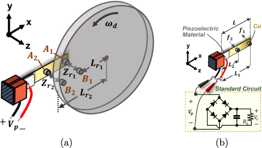
Figure 2. (a) Schematic presentation of a piezoelectric energy harvester beam impulsively excited by two-point rotatory magnetic plucking. (b) The harvester is attached to the standard interface for AC-DC conversion.
Download figure:
Standard image High-resolution imageNotice that the magnetic forces  and
and  are impulsive in nature. Indeed, set
where γ is the angle of revolution. As  actually depends on
  , it can be shown that [51]
for small γ. Thus, the peak magnitude of  is concentrated at around γ = 0 and is very sharp for small αi
, as illustrated in figure 3(a). Note that the parameters of figure 3(a) are drawn from the our experiment shown in figure 3(b) which will be described in section 3.
is concentrated at around γ = 0 and is very sharp for small αi
, as illustrated in figure 3(a). Note that the parameters of figure 3(a) are drawn from the our experiment shown in figure 3(b) which will be described in section 3.
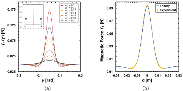
Figure 3. (a) Illustration of the magnetic force  against the angle of revolution γ for various magnitudes of
  . (b) The magnetic coefficient
  is experimentally determined by fitting the experimental observations (yellow points) to equation (3) plotted against the horizontal distance d between two magnets.
Download figure:
Standard image High-resolution imageNext, suppose the harvester is attached to the AC-DC standard interface circuit consisting of a full-bridge rectifier followed by a smoothing capacitor in parallel with a resistive load RL , as illustrated in figure 2(b). The cantilever beam consists of a substrate and a piezoelectric layer partially paved on the top of the beam as also shown in figure 2(b). It is excited due to the non-contact rotary magnetic plucking, giving rise to energy harvesting by the direct piezoelectric effect. The explanation is developed according to two different scenarios as presented below.
2.1. Single resonant mode induced by one-point rotary magnetic plucking
Consider the first case where only the tip magnet A1 is retained and the second magnet A2 is removed. This setup is based on the one-point rotary magnetic plucking and has been theoretically studied by Shu et al [51]. We briefly describe their approach below for the ease of extension to the setup of two-point magnetic plucking as shown in figure 2. They suggested applying the Fourier technique to the impulsive function  for analyzing the phenomenon of frequency up-conversion. Indeed, let
where  are the coefficients of the Fourier cosine expansion of
  defined by equation (3). Equation (7) suggests the resonant vibration of the harvester beam could be achieved as long as
  where
where  introduced in equation (1) is the first resonant frequency of the beam. Thus, many more discrete peaks appear in the relevant frequency response diagram whenever the driving frequencies are equal to the first resonant frequency divided by some integer, as indicated by equation (1). The device therefore exhibits the phenomenon of the nth frequency up-conversion transforming the low rotational driving frequency into the high resonant vibration.
In addition, it was shown that the electromechanical response of the device could be described by the reduced formulation whenever  [51]
[51]
where  can be viewed as time-varying magnitude of the modal shape function of the first resonant mode,
  is the voltage across the piezoelectric element, I(t) is the current flowing into the standard interface circuit. Besides, M1, η1, K1, Θ1 and Cp
are the effective mass, mechanical damping coefficient, the stiffness, the piezoelectric coefficient and the capacitance of the piezoelectric harvester beam, respectively. Now we can imitate the familiar case of a harvester under rectilinear harmonic excitation to solve the simplified formulations as in equation (8). Indeed, the DC harvested power Ph
can be obtained from the work by Shu and Lien (see equation (30) in [5]) who analyzed AC-DC power harvesting and showed
is the voltage across the piezoelectric element, I(t) is the current flowing into the standard interface circuit. Besides, M1, η1, K1, Θ1 and Cp
are the effective mass, mechanical damping coefficient, the stiffness, the piezoelectric coefficient and the capacitance of the piezoelectric harvester beam, respectively. Now we can imitate the familiar case of a harvester under rectilinear harmonic excitation to solve the simplified formulations as in equation (8). Indeed, the DC harvested power Ph
can be obtained from the work by Shu and Lien (see equation (30) in [5]) who analyzed AC-DC power harvesting and showed
2.2. Mixed resonant modes induced by two-point rotary magnetic plucking
The conventional magnetic plucking for piezoelectric-based frequency up-conversion harvesters in aforementioned literatures is based on the plucking at the beam tip [51, 53, 61, 62, 64]. This method is, however, not sufficient to excite the higher resonant modes for broadband energy harvesting. It therefore motivates the idea of the inclusion of the second magnetic pair A2 and B2 for inducing the resonant vibration of the second mode, as suggested by figure 2. The methodology is similar to the previous case based on the one-point magnetic plucking. But there are two main differences. First, the impulsive-like magnetic force  will be replaced by the modal forces
  which are the linear combination of
  weighted by the standard modal shape function. Second, the reduced single mode formulations by equation (8) will be replaced by the multi-mode coupled formulations whose equivalent circuit model is similar to the case of parallel connection of piezoelectric oscillators excited at different harmonics. The analysis therefore can follow that originally applied to the piezoelectric harvester array connected to different nonlinear interface circuits [18–20].
Specifically, let the second magnet A2 be placed at around the middle position of the beam. In addition, the impulsive magnetic forces  and
and  are designed in the opposite direction. This gives the opportunity for inducing the beam deflection similar to that of the second resonant mode. The deflection of a beam
  is then approximated to be

where  and
and  are the shape functions of the first and second resonant modes with
  and
and  as time-varying amplitudes. In the present case of a piezoelectric sheet not covering the whole substrate beam, the determination of these two modal shape functions can be found in literatures [65, 66]. In addition, based on the standard modal analysis or the parametric distributed method in piezoelectric harvesters [1], the modal forces
  and
and  on the first and second resonant modes are realized as
where  is given by equation (4).
To see how the impulsive-like modal force  incites the ith resonant mode of vibration, the Fourier technique briefly described in section 2.1 is employed again for analyzing the phenomenon of frequency up-conversion [51]. Specifically, the Fourier cosine expansion originally applied to
  in equation (7) is applied to the modal forces
  respectively by
It has been shown that  will remain non-vanishing for sufficiently large numbers of ni
if the ratio αi
defined by equation (5) is small [51]. Next, if some integers n1 and n2 are such that
will remain non-vanishing for sufficiently large numbers of ni
if the ratio αi
defined by equation (5) is small [51]. Next, if some integers n1 and n2 are such that  and
and  (
( ), the first two resonant modes could be excited simultaneously. The associated reduced formulations are therefore [17, 18]

Above, the variables  , I(t) and the parameters Mi
, ηi
, Ki
,
, I(t) and the parameters Mi
, ηi
, Ki
,  and Cp
are the same as those defined in equation (8). For example, Ki
is the effective stiffness evaluated at the ith resonant mode.
and Cp
are the same as those defined in equation (8). For example, Ki
is the effective stiffness evaluated at the ith resonant mode.
As the chosen AC-DC interface circuit, shown in figure 2(b), consists of nonlinear circuit elements, it makes analyzing equations (14)–(16) much more difficult than the case of simply attaching to a resistive load. Fortunately, Lien and Shu [18] have introduced the equivalent load impedance  for analyzing the harvester array attached to various nonlinear interface circuits. Based on this approach, it is shown that the circuit elements consisting of the piezoelectric capacitance Cp
in parallel with the interface circuit are replaced by an equivalent load impedance
for analyzing the harvester array attached to various nonlinear interface circuits. Based on this approach, it is shown that the circuit elements consisting of the piezoelectric capacitance Cp
in parallel with the interface circuit are replaced by an equivalent load impedance  , as illustrated by the dashed rectangle box in figure 4. In the present case of the standard AC-DC interface,
  is explicitly expressed by [18]
Next, equations (14)–(16) can be interpreted by introducing an equivalent RLC circuit model
as resistor, inductance, capacitance and voltage source, respectively [18]. The piezoelectric voltage Vp
related to  gives
gives

where  is called the velocity current [18]. This circuit model is schematically presented by figure 4 and its mathematical formulations in the frequency domain is provided by
where  and
and  are the corresponding Fourier transforms of
  and
and  . It therefore gives
where
The harvested power Ph is taken the real part of
where  is the total velocity current, the superscript * denotes the complex conjugate, and T is the period covering
  and
and  . It can be shown that

where  is the ij component of
  defined by equation (23).
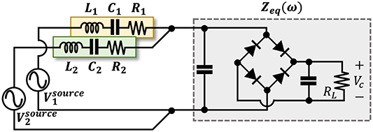
Figure 4. An equivalent circuit model representing two resonant modes of vibration.
Download figure:
Standard image High-resolution imageFinally, if the resonant frequencies are widely separated as often seen in the beam structure, i.e.  , then the contributions to power from the crossing terms
  in equation (23) are negligible. The harvested power is therefore simplified to be
3. Experiment
The experimental setup similar to that schematically presented in figure 2(a) is now shown in figure 5. A cantilever beam is clamped by a fixture mounted on a stationary base. It consists of a Cu substrate and a partial piezoelectric layer made by Eleceram Technology (Taiwan). The size of the Cu substrate is  , and that of the piezoelectric attachment is
  . A motor (SGM7G-13AFA61) and its controller (SGD7S-120A00A008) are chosen to drive the rotating plate. The standard interface circuit schematically described by figure 2(b) is attached to the harvester. The piezoelectric voltage Vp
and the output DC voltage Vc
across the load
. A motor (SGM7G-13AFA61) and its controller (SGD7S-120A00A008) are chosen to drive the rotating plate. The standard interface circuit schematically described by figure 2(b) is attached to the harvester. The piezoelectric voltage Vp
and the output DC voltage Vc
across the load  are measured by the designed LabVIEW program for different driving rotational frequencies. All of the measurements are recorded through the DAQ device (NI 9229).
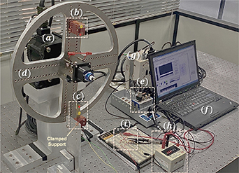
Figure 5. Experimental setup: (a) motor, (b) rotating magnets B1 and B2, (c) a piezoelectric cantilever beam with magnets A1 and A2 attached on it which is clamped by a fixture, (d) a rotating plate, (e) DAQ for data acquisition, (f) laptop installed with LabVIEW, (g) motor controller, (h) resistance substitution box, (i) standard interface circuit.
Download figure:
Standard image High-resolution imageThere are two magnets A1 and A2 attached on the beam and the distances to the end of the beam are  mm and
  mm. Another pair of magnets B1 and B2 are aligned radially on the rotating plate with the radii of revolution
  mm and
  mm. The perpendicular distance
  between A1 and B1 is 10.2 mm and
  between A2 and B2 is 9.6 mm. All of these notations are schematically illustrated in figure 2.
The measurements start from realizing the magnetic interaction forces characterized by the coefficient  and
and  in equation (3). These two coefficients are obtained by matching the theoretical prediction, as in equation (3), to the experimental observations (see, for example, figure 5 in [51]). It is illustrated in figure 3(b) where the magnetic forces are measured under various horizontal distances d between two magnets. The measured results are
  N m4 and
  N m4. The negative sign in
  is due to the opposite directions of magnetic forces
  and
and  . The Fourier coefficients
  and
and  of different modes are therefore determined by numerical integration of equation (13) for different integers. The results are listed in table 1. Next, the equivalent parameters measured at the first resonant mode, as in equation (8) for the setup of one-point magnetic plucking, are identified based on the standard modal testing. They are presented by table 2. Furthermore, for the setup under the two-point magnetic plucking, the equivalent parameters of the harvester beam evaluated at the first and second resonant modes, as in equations (14)–(16), are measured and listed in table 3.
Table 1. Fourier cosine coefficients  of the magnetic modal forces
  .
.
| n1 | 3 | 4 | 5 | 6 | 7 | 8 | 9 | 10 | 11 | 12 |

| 3.355 | 3.40 | 3.448 | 3.50 | 3.552 | 3.601 | 3.646 | 3.685 | 3.716 | 3.739 |
| n2 | 16 | 17 | 18 | 19 | 20 | 21 | 22 | 23 | 24 | 25 |

| 2.169 | 2.173 | 2.174 | 2.173 | 2.170 | 2.160 | 2.150 | 2.137 | 2.121 | 2.102 |
Table 2. Equivalent parameters of the device under the one-point rotary magnetic plucking. The notation  denotes the short-circuit resonant frequency.
| M (kg) | η (N sec m−1) | K (N m−1) | Θ (N V−1) | Cp (nF) |
 (Hz) (Hz) |
|---|---|---|---|---|---|

|

| 114.4 |

| 12.8 | 50.2 |
Table 3. Equivalent parameters of the device under the two-point rotary magnetic plucking. The notation  denotes the short-circuit resonant frequency.
| M (kg) | η (N sec m−1) | K (N m−1) | Θ (N V−1) | Cp (nF) |
 (Hz) (Hz) | |
|---|---|---|---|---|---|---|

|

|

| 110.0 |

| 12.8 | 47.6 |

|

|

| 10 006.0 |

| 12.8 | 250.1 |
4. Results and discussions
The experimental results are discussed according to two different scenarios. Consider the first setup excited by the one-point rotary magnetic plucking. Therefore, only the first resonant mode can be induced under this operation. The DC voltage frequency response evaluated at the optimal load  kΩ is plotted in figure 6(a). The analytic predictions obtained from equation (9) with parameters given by table 2 are presented individually by various continuous blue curves according to distinct integers
  . They are found in reasonable agreement with the experimental observations presented by red points. Notice that the diode loss inevitable in the practical power conditioning process is not taken into account in the previous theoretical modeling. It is included here by setting the voltage drop 1.4 volt in equation (A4) proposed by Wu et al [22] for the fair comparison between the prediction and experiment. The details of descriptions are omitted for brevity. The next observation is that the harvested DC voltage is concentrated on certain specific discrete frequencies of narrow band, such as 5.6 Hz (
 ), 6.3 Hz (
 ), 7.2 Hz (
 ), 8.4 Hz (
 ), 10.0 Hz (
 ) and 12.6 Hz (
 ), etc. However, it is immediately reduced from the peak value of 7–10 volt to 0.6 volt within the adjacent frequencies of peak output described above, as clearly demonstrated in figure 6(a). Finally, the time waveform of the piezoelectric voltage measured at around
  Hz (
Hz ( ) is shown in figure 7(a). Its FFT plot presented in figure 7(d) exhibits a sharp peak located at around 50 Hz which is close to
  of the device (see table 2) in the frequency domain. This confirms the harmonic extracted from the voltage frequency response in figure 6(a) is mainly attributed to the first resonant mode of the harvester.

Figure 6. The comparison of DC voltage response against frequency between the analysis and experiment. (a) is the setup excited by the one-point rotary magnetic plucking. (b) is the setup operated by the two-point rotary magnetic plucking.
Download figure:
Standard image High-resolution image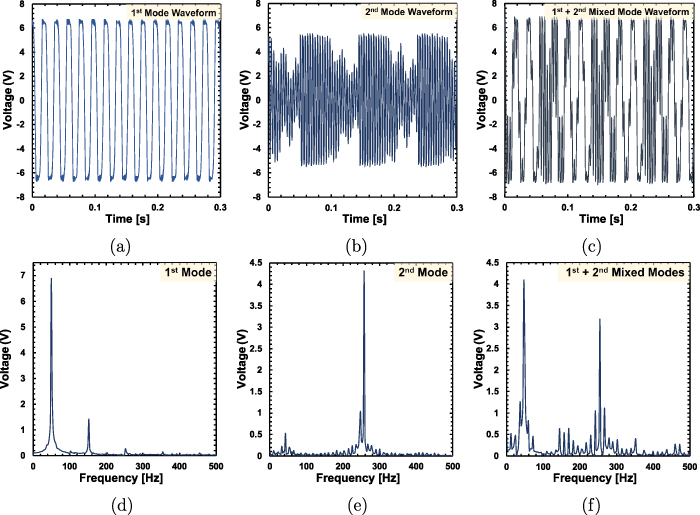
Figure 7. The top three are the time waveforms of the piezoelectric voltage: (a) is measured from the peak voltage of  in figure 6(a); (b) is measured from the peak voltage of
  (second resonant mode) in figure 6(b); (c) is measured from the peak voltage of
  and
and  (mixing of the first two resonant modes) in figure 6(b). Next, the bottom three (d), (e) and (f) are the corresponding FFT plots of the cases (a), (b) and (c), respectively.
Download figure:
Standard image High-resolution imageOn the other hand, the electrical response of the second setup allowing two-point rotary magnetic plucking exhibits the significant contrast in comparison to the previous case. Indeed, the DC voltage frequency response evaluated at the load  kΩ is shown in figure 6(b) where the experimental observations are presented by red points. The analytic predictions are obtained from equation (25) evaluated at various integers n1 and n2. They are presented by blue curves for the second resonant mode of vibration and are presented by yellow curves for the mixed resonant modes of vibration, respectively. Obviously, figure 6(b) shows a good agreement with the experimental observations. In addition, the discussions of these results are classified into two cases according to the different types of resonant modes.
- (I)Suppose only the second resonant mode is triggered by the specific driving frequency fd ; i.e.
 but where and are defined by equation (1) and equation (2). An example of this case is Hz and in figure 6(b) so that Hz. The waveform of the piezoelectric voltage is shown in figure 7(b) and its FFT plot shown in figure 7(e) justifies the main contribution of harmonics results from the second resonant mode of vibration. In addition, from figure 6(b), the lowest magnitude of measured DC output voltage is about 3.0 volt within the frequency range between 10–12 Hz. This range within the adjacent frequencies of peak voltage is labelled by and , as shown in figure 6(b). In comparison with the off-resonant frequency range between 10.5–12 Hz (the neighboring frequency between the peaks labelled by and ) shown in figure 6(a), the DC voltage generated by the first setup is as low as around 0.6 volt. It shows that the harvested power is increased up to 2500% () in the off-resonance region of figure 6(a). This confirms the proposed device offers an advantage of inducing broadband frequency up-conversion operated by two-point rotary magnetic plucking.
 - (II)Suppose both the first two resonant modes of vibration are induced by some driving frequency fd ; i.e. and . In other words, there exist some integers n1 and n2 such that the driving frequency fd
satisfies the conditions Hz and Hz. An example of it is Hz, and as illustrated in figure 6(b). The corresponding time waveform of the piezoelectric voltage is shown in figure 7(c) and its FFT presentation is shown in figure 7(f). Clearly, the FFT plot exhibits two very sharp peaks evaluated at around 47 Hz and 250 Hz. This provides an additional proof showing the harmonics extracted from figure 7(c) are mainly attributed to the mixing of the first two resonant vibrations. A consequence of it is that the output voltage is enhanced to 6.7 volt, giving rise to significant power boosting in comparison with the previous case (I).


A closing remark is about the feasibility of using equation (26) for replacing the complex formula equation (25). Indeed, it can be shown that in the present case the contributions to the total power output from the crossing terms  in equation (23) are less than 0.15%. Thus, the use of equation (26) is legitimate as long as the resonant frequencies of the device are widely separated.
5. Conclusions
The article shows that the significant broadband energy harvesting can be accomplished by inducing the mixed resonant modes of vibration under the two-point rotary magnetic plucking. The proposed device consists of a piezoelectric cantilever beam connected to the standard AC-DC interface circuit. It is designed to allow two impulsive magnetic forces with opposite directions, acting simultaneously on the beam so that the second resonant mode of vibration can be induced by impulsive excitations. A theoretical model is established for explaining the electrical response of the proposed harvester. It is based on the Fourier decomposition of magnetic impulsive forces and the equivalent load impedance originally proposed for analyzing harvester arrays. The former is for realizing the phenomenon of frequency up-conversion and the latter is for the replacement of nonlinear interface circuit. The analytic estimate of DC power output is derived considering the effect of mixed resonant modes of vibration.
The predictions are validated by experiments carried out under the two different scenarios. The first one adopts the conventional approach allowing the plucking only at the tip magnet (one-point magnetic plucking), giving rise to inducing a single resonant mode of vibration. It exhibits the significant output voltage generated at several discrete number of driving frequencies. However, the voltage drops to 0.6 volt in the off-resonance region between the adjacent frequencies of peak voltage, as shown in figure 6(a). Such a drawback is overcome by the proposed setup allowing the two-point magnetic plucking for triggering mixed resonant modes, as confirmed by figure 6(b). In addition, the lowest level of output voltage is observed to be around 3 volt within the wide frequency range between 5–15 Hz. Thus, the DC output power is enhanced at least to 2500% higher than that in the off-resonant frequencies of the first setup, showing the remarkable feature of broadband energy harvesting.
Data availability statement
All data that support the findings of this study are included within the article (and any supplementary files).
Acknowledgment
The support from Ministry of Science and Technology through the Grant No. 108-2221-E-002-004-MY3 is highly appreciated.