

Abstract
For advanced microrobots such as an in-pipe working microrobot with dexterous micromanipulators, a novel multi-degree of freedom (DOF) soft microactuator integrated with flexible electro-rheological microvalves (FERVs) using an alternating pressure source was proposed and developed. The concept of the proposed actuator includes a series connection of multiple one-DOF microactuator units, built-in FERVs, and an alternating pressure system. The one-DOF soft microactuator unit consists of a bending fluidic actuator part and the FERVs. The FERV made from flexible materials controls electro-rheological fluid (ERF) flow by its viscosity change with the electric field applied through fixed electrodes. The alternating pressure of the ERF is supplied with only one pipe and rectified with the synchronously on/off-controlled FERVs. The benefits of the proposed actuator are (a) compact design with built-in FERVs and the alternating pressure system, (b) multi-DOF actuator with simple structure, and (c) closed system suitable for independent microrobots. In this paper, as a basic module, a 20 mm long two-DOF soft microactuator with two actuator units was developed. Through simulation, the length ratio of the one-DOF soft microactuator units were determined. The material of the fluidic chambers was selected by fabricating and testing the bending fluidic actuator parts. Then the designed microactuator was successfully fabricated using MEMS technologies. Through experiments, the tip displacements, the response, and the output forces were clarified. The two-DOF motion was realized and the validity of the proposed actuator was confirmed.
Export citation and abstract BibTeX RIS
1. Introduction
In recent years, a soft microactuator has gained much attention due to its multiple benefits such as the ability to safely interact with the environment [1], ability to perform highly dexterous tasks [2], high resiliency [3], and high resistance to mechanical damage [4]. A fluidic soft microactuator is a typical soft microactuator composed of a deformable elastic structure with fluidic chambers inside that can be enlarged when fluidic pressure is applied to them. The fluidic soft microactuator has a simple structure and can achieve different modes of deformation including, bending [5, 6], twisting [7], contraction/expansion [8, 9], and multi-degree of freedom (DOF) motion [10] with a specific design. Due to the benefits and flexibility of a fluidic soft microactuator, it is highly suitable for an advanced microrobot that performs complex and sensitive tasks with dexterous manipulating components in narrow spaces such as inside the human body, inside small diameter pipe, etc [11]. With advanced fluidic soft microactuators having multiple DOFs, integrated microvalves, and a simple and downsized piping system, the microrobot can have a micromanipulator that can reach and grasp an object or move a micro-camera to inspect the environment at a hard-to-reach location as shown in figure 1.
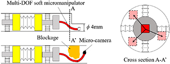
Figure 1. Advanced microrobot with multi-DOF soft micromanipulator.
Download figure:
Standard image High-resolution imageA fluidic soft microactuator can be driven by either pressurized air or liquid. However, a pneumatic pump is difficult to be realized on a micro-scale due to the compressibility of air. In the in-pipe application where the advanced microrobot needs to travel in a complex network of pipelines, the microrobot tethering with an external pneumatic power source is not appropriate. In contrast, a hydraulic soft microactuator in a closed system is much suitable for this kind of application. Various types of microvalves are available for controlling the fluidic soft microactuators: e.g. an electrostatic type [12], a shape memory alloy type [13], a piezoelectric type [14], a pneumatic membrane type [15], a pneumatic tube-buckling type [16], and so on. However, they have complicated structures with moving parts that cause friction, wear, and sticking and degrade their performance. In addition, they are rigid and difficult to be integrated into the soft microactuators. Rigid external microvalves usually result in a bulky valve system that is larger than the actuators themselves, especially when multiple control valves are required to independently control multiple soft microactuators [17].
To realize a simple microvalve without moving parts, electro-rheological microvalves (ERVs) using electro-rheological fluids (ERFs) as the working fluids have been proposed and developed [18–23]. The ERF is a functional fluid whose apparent viscosity can be increased in response to the electric field (ER effect). The ERV is a simple flow channel having a pair of parallel electrodes on the top and bottom walls. When an electric field is applied to the ERF passing through the ERV with the electrodes, the increased apparent viscosity increases the pressure drop across the ERV up to the ER effect index (κER) times [22]. Figure 2(a) exemplifies the usage of ERV with a bending microactuator. At the original state, the pressure drop across the ERV is P0. When the maximum electric field (a few kV mm−1) is applied, the pressure drop across the ERV increases up to κER P0, increasing the internal pressure of the microactuator. In addition, to realize a flexible microvalve, flexible electro-rheological microvalves (FERVs) have been proposed and developed, which are a cantilever type [24], divided electrode type [25], and hybrid structure type [26]. The FERVs are made from flexible materials, and they can be integrated into the soft microactuators, which can remove the bulky external control valves as shown in figure 2(b), especially when there are multiple microactuators to be controlled separately.
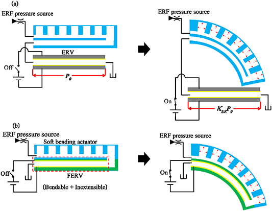
Figure 2. Working principle of microactuator controlled with: (a) ERV and (b) FERV.
Download figure:
Standard image High-resolution imageFor a multi-DOF ER microactuator and/or multiple ER microactuator system, the piping becomes an essential problem because each fluidic chamber in the soft microactuators needs two pipelines for supply and return, which results in a bulky and complicated piping system. To overcome the problem, an alternating pressure system was proposed as exemplified in figures 3(a) and (b) [27]. The system consists of an alternating pressure source (APS) and ER soft microactuators, each of which has two fluidic chambers inside connected to ERVs. The alternating flow supplied to the ER soft microactuator is rectified with the synchronously on/off controlled ERVs and transfers the ERF from one fluidic chamber to the other fluidic chamber causing bending motion. Since the number of pipelines becomes half, the diameters of pipelines can be small with low viscosity working fluid to transmit the alternating pressure through a pressure transmitter, and the system does not require the fluidic reservoir tank, the system can be smaller and simpler. In our previous research [28], a one-DOF bending microactuator integrated with FERVs using an APS was proposed and developed as shown in figures 3(c) and (d). The integrated FERVs can be bent along with the microactuator while still functioning as microvalves. However, the multi-DOF soft microactuator has not been realized.

Figure 3. Working principle of alternating pressure system: (a) suction phase using ERVs, (b) pumping phase using ERVs, (c) suction phase using FERVs, and (d) pumping phase using FERVs.
Download figure:
Standard image High-resolution imageIn this paper, a novel multi-DOF soft microactuator integrated with FERVs using an APS is proposed and developed. In order to realize multi-DOF bending motion while integrated with FERVs, the proposed soft microactuator is designed by connecting multiple one-DOF bending microactuator units in series. Finite element method (FEM) simulations are conducted to investigate the maximum displacement and output force at the tip in each direction and to optimize the design of the proposed soft microactuator. Then, a prototype of the two-DOF soft microactuator integrated with FERVs is fabricated and connected to an APS to experimentally clarify its bending characteristics.
2. Proposal of multi-DOF soft microactuator integrated with FERVs using APS
In order to acquire a multi-DOF function, the soft microactuator needs multiple fluidic chambers and multiple FERVs to control each fluidic chamber independently as shown in figure 4(a). To easily control the bending in two directions perpendicular to each other, four pairs of fluidic chambers and FERVs are needed. Figure 4(b) shows a possible design for the four-chamber soft microactuator integrated with FERVs. In this design, the FERVs are integrated into the middle layers between fluidic chambers on the horizontal and vertical planes. The soft microactuator can bend in the horizontal direction by applying high pressure to a pair of chambers A and C or chambers B and D. It can also bend in the vertical direction by applying high pressure to a pair of chambers A and B or chambers C and D. Applying pressure into one chamber will result in an oblique bending motion. However, the flexural rigidity of the FERV in the lateral direction is very high due to the width of the FERV. This makes the soft microactuator integrated with FERVs in this design unable to achieve large bending angle in both directions. In addition, the fabrication process would be very complicated or difficult, since this design has a complex three-dimensional structure for the FERV layers. Figure 4(c) shows another possible arrangement of the FERVs. In this design, the soft microactuator can bend in the vertical direction; however, it is still unable to acquire large bending angle in the horizontal bending. In the past, there was a research about two-DOF FERV using short but multiple solid ERVs connected together in series with small flexible wires [29]. However, the connecting wires between the micro-sized solid electrodes are very difficult to fabricate by the MEMS fabrication process. It is a very challenging matter to minimize this structure into micro-scale.

Figure 4. Two-DOF soft microactuator: (a) conventional design with four chambers, (b) cross section A–A' with FERVs on both vertical and horizontal planes, (c) cross section A–A' with FERVs only on horizontal plane, (d) proposed design, and (e) cross section B–B'.
Download figure:
Standard image High-resolution imageIn order to solve this problem, in this study, a design of connecting multiple one-DOF bending microactuator units integrated with FERVs together in series was proposed to create a multi-DOF soft microactuator. Each one-DOF bending microactuator has the FERVs integrated into the middle layer between fluidic chambers. As an example, a two-DOF soft microactuator is shown in figure 4(d). The 2nd soft microactuator unit (2 MA) is rotated at 90° around the center axis before connecting to the 1st soft microactuator unit (1 MA). 1 MA is used for bending in the vertical direction, while 2 MA is used for bending in the horizontal direction. This results in achieving two-DOF motion of the soft microactuator without the effect of the high flexural rigidity of the FERV in the lateral direction. The length ratio of 1 MA and 2 MA can be determined to have desirable bending characteristics. The two-DOF soft microactuator is one module and multiple modules can be connected in series to create higher-DOF soft microactuator as shown in figure 5(a).
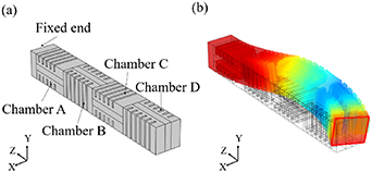
Figure 5. Multi-DOF soft microactuator: (a) model of two modules connected in series, (b) an example of FEM simulation results with pressure 90 kPa in chamber A and 60 kPa in chamber B, and 200 kPa in chambers C and D.
Download figure:
Standard image High-resolution imageFigure 5(b) shows an example of the FEM simulations. In this simulation, pressures of 90 kPa and 60 kPa were applied to chambers A and B, and, at the same time, a pressure of 200 kPa was applied to chambers C and D. The pressure applied to chamber A caused the soft microactuator unit to bend in the +Y direction, while the pressure applied to chamber C caused the tip part of the soft microactuator unit to bend in the −Y direction. A similar case occurred for chambers B and D, but the bending motions were in the −X and the +X directions. This resulted in a wide variety of the shape and the tip direction of the soft microactuator. This multi-DOF microactuator can be very useful as a soft micromanipulator of a microrobot. As shown in figure 1, the multi-DOF soft micromanipulator can bring either a microgripper or a micro-camera into a narrow space that the microrobot itself is unable to reach. In this paper, as an essential component of the multi-DOF soft microactuator, the two-DOF soft microactuator (one module) was investigated.
The proposed multi-DOF soft microactuator was considered to utilize the alternating pressure system. This is because the soft microactuator units connected in series need flow channels for supplying ERF. By utilizing the alternating pressure system, only one flow channel is needed to supply ERF and control all of the fluidic chambers, as shown in figure 4(e). Since the flow channel integrated into the soft microactuator needs to be connected together, only one flow channel simplifies the connection part between the soft microactuator units dramatically. To supply the ERF to 2 MA, another layer of flow channel was added under the FERV layer. This is because the width of the soft microactuator was limited and the FERV layer already had flow channels for two FERVs.
3. Design and fabrication of the proposed soft microactuator
3.1. Design and simulation
The two-DOF soft microactuator connecting two one-DOF soft microactuator units integrated with FERVs was designed and fabricated. The dimensions of each one-DOF microactuator unit and the simulation method used in this section were based on our previous work [28] since they had been optimized to obtain the maximum bending angle and output force. The overall outer dimensions of the two-DOF microactuator were 3 mm × 3 mm × 20 mm (width × height × length). There are the following two reasons: the requirements for the application shown in figure 1, and the fabrication limitation of the FERV. Figure 6(a) shows the proposed two-DOF soft microactuator model where the sizes of 1 MA and 2 MA were similar with outer dimensions of 3 mm × 3 mm × 10 mm (width × height × length). The number of chamber units of each fluidic chamber was 11. The relationship between the simulated bending angle α, tip displacement d, and Young's moduli are shown in figure 6(b).
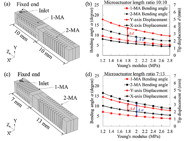
Figure 6. Simulation results of two-DOF soft microactuator: (a) three-dimensional model with length ratio of 10:10, (b) bending angle and tip displacement with different Young's moduli of 1 MA and 2 MA (10:10), (c) three-dimensional model with length ratio of 7:13, and (d) bending angle and tip displacement with different Young's moduli of 1 MA and 2 MA (7:13).
Download figure:
Standard image High-resolution imageFrom the simulation results in figure 6(b), the bending angle of 1 MA is slightly lower (0.71–0.74 times) than that of 2 MA because the thickness of 1 MA is slightly higher than 2 MA due to the supply layer. However, the tip displacement on the Y-axis is 2.20–2.24 times larger than that on the X-axis. This is because the length of 2 MA amplifies the magnitude of displacement in the Y-axis of 1 MA. In order to reduce the difference in tip displacements between the X and the Y-axes (Δd), the 1st method is to increase the pressure applied to the fluidic chambers of 2 MA. Another method is to reduce the length of 1 MA and increase the length of 2 MA. In this study, the method of changing the lengths of 1 MA and 2 MA was utilized because it can utilize the same alternating pressure from an APS. Figure 6(c) demonstrates another model with the length of 1 MA of 7 mm, while the length of 2 MA is 13 mm, maintaining the total length of 20 mm. The length of 1 MA was determined to be the minimum value for the FERV in the previous study [26]. Compared to the results in figure 6(b), the simulation results in figure 6(d) shows the increase of bending angle difference (Δα), while the tip displacement difference (Δd) was decreased significantly. Therefore, in this work, the length ratio of 7:13 was utilized for the two-DOF soft microactuator. The detailed dimensions of 1 MA and 2 MA are shown in figure 7.

Figure 7. Schematics and dimensions of chambers for 1 MA and 2 MA.
Download figure:
Standard image High-resolution imageFor simplifying the design, in this study, only the connection of the flow channel inside the soft microactuator was considered. The electrodes for 1 MA and 2 MA were connected separately outside the soft microactuator.
3.2. Material of the proposed soft microactuator
From the simulation results shown in figure 6(d), Young's modulus of the material used in the soft microactuator affects the bending angle of the soft microactuator. In order to maximize the bending angle, the material for the soft microactuator was investigated in this study. One of the most common materials used in soft microactuator fabrication is Sylgard-184 (Dow, Inc.), with Young's modulus of 2.6 MPa. Another commonly used elastomer with the lowest Young's modulus for fabricating soft microactuators is Ecoflex (Smooth-On, Inc.), with Young's modulus of 0.1 MPa. However, since Young's modulus is very low, it is very difficult to fabricate the micro-scale complex structure with a high aspect ratio and multiple bonding processes. As for the other commercialized elastomers, their viscosities are high, and it is difficult to use in micro-scale complex structure fabrication. To select the best material for the soft microactuator, the blended elastomer of two different elastomers were investigated. Several studies demonstrated that mixing two elastomers can result in a blend elastomer with adjustable material properties [30–32]. In this work, several fluidic soft microactuators were fabricated using different blended materials. The design of the top and bottom chambers of the fluidic soft microactuator was the same as that of our previous work, but the middle FERV layer was replaced by a 0.6 mm thick Sylgard-184 slab for simplicity. An experiment was conducted to compare the materials by applying the top chamber, while the bottom chamber was open to atmospheric pressure as shown in figure 8(a). Then, the pressure for the maximum bending (figure 8(b)) and the burst pressure were recorded and shown in table 1. There was no leakage after bonding, and the soft microactuators can be used at pressure lower than the burst pressure without leakage.

Figure 8. An example of the fabricated fluidic soft microactuator made from Sylgard-184: (a) the original shape (zero pressure) and (b) the maximum bending with pressure of 80 kPa.
Download figure:
Standard image High-resolution imageTable 1. Experimental results of the soft microactuators made from different materials.
| Materials | Pressure for maximum bending (kPa) | Burst pressure (kPa) |
|---|---|---|
| Sylgard-184 | 80 | 200 |
| Sylgard-184 + Ecoflex00-10 (5:1) | 60 | 120 |
| Sylgard-184 + Ecoflex00-10 (3:1) | 55 | 100 |
| Sylgard-184 + Ecoflex00-10 (1:1) | 40 | 90 |
| SIM260 + Ecoflex00-10 (3:1) | 85 | 300 |
| SIM260 + Ecoflex00-10 (1:1) | 50 | 280 |
Three kinds of elastomers were used in this experiment: Sylgard-184, Ecoflex00-10, and SIM260 (Shin-Etsu Chemical Co. Ltd). From the results show in table 1, the blended elastomer of Sylgard-184 and Ecoflex00-10 with the ratio of 5:1 (Sylgard-184 + Ecoflex00-10 (5:1)) provided higher flexibility to the soft microactuator (compared to Sylgard-184); however, the burst pressure was also lower. Increasing the ratio of Ecoflex00-10 in the blend resulted in higher flexibility and lower burst pressure. Since the force provided by the pneumatic/hydraulic actuator is dependent on the applied pressure, low burst pressure means low potential for applying force. Thus, those materials are not suitable for the proposed soft microactuator. SIM260 is another elastomer with a higher Young's modulus than that of Sylgard-184, and the blended elastomers of SIM260 and Ecoflex00-10 (1:1) showed not only high burst pressure but also high flexibility of the soft microactuator. The Young's modulus of SIM260 + Ecoflex00-10 (1:1) was estimated to be about 1.8 MPa from the experimental result. Therefore, in this work, SIM260 + Ecoflex00-10 (1:1) was used as the material for fabricating the proposed soft microactuator.
3.3. Fabrication of the proposed soft microactuator
The 1st step of the fabrication process was to fabricate the FERV layer and the supply layer. The dimensions of the 1st and the 2nd FERV layers for 1 MA and 2 MA are illustrated in figures 9(b) and (c). The design of the FERV layers was the same as that of our previous study [26]. Each FERV layer had two FERVs: one with the outlet on one side and another with the outlet on the opposite side. The FERV layers were made from a combination of UV-curable PDMS and SU-8 for the structure, and UV-curable PEDOT:PSS for the electrodes. Each FERV channel's dimensions were 0.4 mm × 0.07 mm × 5 mm (width × height × length) (detail dimensions are illustrated in supplementary document figure S1 (available online at stacks.iop.org/SMS/30/085006/mmedia)). The supply layer for supplying ERF to 2 MA was designed to be located under the 1st FERV layer and is shown in figure 9(a). The supply layer had a through-hole to connect the outlet of the FERV for chamber B. The dimensions of the flow channel of the supply layer were 1.1 mm × 0.1 mm × 13 mm (width × height × length). This resulted in the flow resistance of the supply layer flow channel being 1/3 of the flow resistance of the FERV. The detail of the supply layer's fabrication process is shown in figure S2 in the supplementary document.
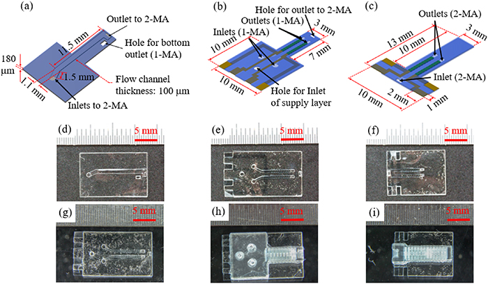
Figure 9. Parts of two-DOF soft microactuator: design of (a) supply layer, (b) 1st FERV layer, and (c) 2nd FERV layer; images of fabricated (d) supply layer, (e) 1st FERV layer, (f) 2nd FERV layer, (g) supply layer bonded with first FERV layer, (h) 1 MA, and (i) 2 MA.
Download figure:
Standard image High-resolution imageFigures 9(d)–(f) demonstrate the images of the successfully fabricated 1st FERV layer, the 2nd FERV layer, and the supply layer, respectively. In the assembling process, firstly, the supply layer was bonded with the first FERV layer (figure 9(g)) using O2 plasma bonding. Secondly, the chambers of 1 MA and 2 MA were fabricated with the blended elastomer (SIM260 + Ecoflex00-10 (1:1)) using a molding method. Thirdly, the successfully fabricated 1 MA and 2 MA chambers were bonded to the previously fabricated FERV as shown in figures 9(h) and (i). Detail of the fabrication and the bonding processes of the microactuator chambers can be found in our previous work [28]. Finally, 1 MA and 2 MA were bonded together. For this bonding process, the successfully fabricated 1 MA and 2 MA were both stamped on a glass wafer spin-coated with uncured PDMS (6000 rpm/30 s). Then, both soft microactuator units were aligned in a bonding jig and baked in an oven at 100 °C for 30 min. The bonded soft microactuator unit was removed from the jig, more uncured PDMS was applied to the bonding part, and the device was baked at 100 °C for 30 min to strengthen the bonding and prevent leakage in 1 MA and 2 MA. The PDMS block with the PDMS tube was attached to the inlet of 1 MA for connecting to the APS. Figure 10(a) shows the overall assembly method of each part. At the tip of 1 MA and the base of 2 MA, there was a groove (1 mm × 0.6 mm × 1.8 mm (width × height × length)) that formed a closed connecting chamber after the 1 MA and 2 MA were connected. The successfully fabricated two-DOF soft microactuator is shown in figure 10(b). Take note that the excess parts of the FERV layer on 1 MA and 2 MA can be cut to be the same width as the chamber.
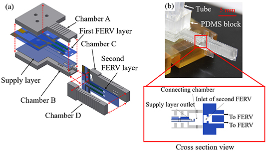
Figure 10. Fabricated two-DOF soft microactuator: (a) three-dimensional exploded view and (b) successfully fabricated two-DOF soft microactuator and its cross-section side view of connection part.
Download figure:
Standard image High-resolution image4. Experiments and discussion
4.1. Bending characteristics of the proposed soft microactuator
In order to demonstrate the bending characteristics of the proposed two-DOF soft microactuator, an experiment was conducted by connecting it to an APS as shown in figure 11(a). The APS consisted of a voice coil motor, a 9 mm diameter and 400 μm thick membrane made from Ecoflex, and a pump chamber. The APS can generate the maximum pressure of 100 kPa and the maximum flow rate amplitude of 1600 mm3 s−1. The voltage control signal generated with a function generator was changed to the current control signal by using a voltage to current converter (V–I converter), then, the output pressure of the APS can be controlled by the control current from the V–I converter. The FERVs need to be controlled synchronously with the alternative pressure to bend the soft microactuator. The synchronous signal from the function generator was applied to a microcontroller unit (MCU). The MCU can adjust the amplitude and phase of the output signals. Two output signals were generated with the MCU: one had the same phase as the control signal of the APS, another had a phase difference with the control signal of the APS by 180° as shown in figure 11(b). The digital output signals from the MCU were changed to analog signals by digital to analog converter, and the analog signals were amplified by high voltage amplifiers (HV Amps) for controlling the FERVs. In this research, only two HV Amps were utilized for simple set up. The microactuator's bending direction can be controlled by connecting HV Amps to FERVs as shown in table 2. Take note that with four HV Amps, it would be possible to separately drive only 1 MA or 2 MA by applying the independent control signals to each FERV. The ERF used in this work was a nematic liquid crystal type. The system was degassed in a vacuum chamber for 2 h before the tube connecting to the ERF tank was closed to form a closed system. From figure 11(c), the pressure measured with the pressure sensor located at the upstream side of the FERVs showed a sinusoidal pressure waveform with a peak-to-peak value of 100 kPa, an offset of 50 kPa, and the frequency of 5 Hz.
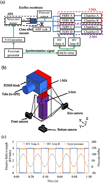
Figure 11. Schematics of experimental set up for two-DOF bending: (a) schematic diagram, (b) camera setup, and (c) time variation of output signals of HV Amps and supply pressure.
Download figure:
Standard image High-resolution imageTable 2. FERV and HV Amp connection for controlling two-DOF soft microactuator.
| Bending direction | Connected HV Amp | |||
|---|---|---|---|---|
| FERV A | FERV B | FERV C | FERV D | |
| +Y/+X | HV Amp A | HV Amp B | HV Amp A | HV Amp B |
| −Y/+X | HV Amp B | HV Amp A | HV Amp A | HV Amp B |
| +Y/−X | HV Amp A | HV Amp B | HV Amp B | HV Amp A |
| −Y/−X | HV Amp B | HV Amp A | HV Amp B | HV Amp A |
The experiment was conducted to demonstrate two-DOF bending without load of the soft microactuator with 1 MA and 2 MA. In this experiment, an electric field strength amplitude of 4 kV mm−1 was utilized. The images of the bent microactuator were taken by a digital camera from three directions as shown in figure 11(b) and the bending angles of the soft microactuator were calculated.
Experimental results are shown in figure 12. Figures 12(a) and (d) show the initial state of the microactuator without applying voltages to the FERVs. Figures 12(b) and (c) show the bending of 1 MA, while figures 12(e) and (f) show the bending of 2 MA. The bending angles of 1 MA α+Y in the +Y direction and α−Y in the −Y direction were 5.3° and 4.9°, respectively, while the bending angles of 2 MA α+X in the +X direction and α−X in the −X direction were 11.0° and 10.0°, respectively. Considering the maximum bending in each direction, the tip displacement in the Y- and X-axes were 3.0 mm and 2.1 mm. In the initial state of 1 MA, there was slight bending in the +Y direction due to the asymmetrical structure of 1 MA with the supply layer and the fabrication errors. The slight bending also occurred in the initial state of 2 MA as well in the +X direction due to the fabrication errors. In addition, there was a slight difference between the bending angles of the +Y/−Y directions. This might be due to the unidentical wall thicknesses in two chambers caused by the fabrication errors. To demonstrate the two-DOF bending motion, images from the bottom of the soft microactuator were shown in figures 12(g)–(k).
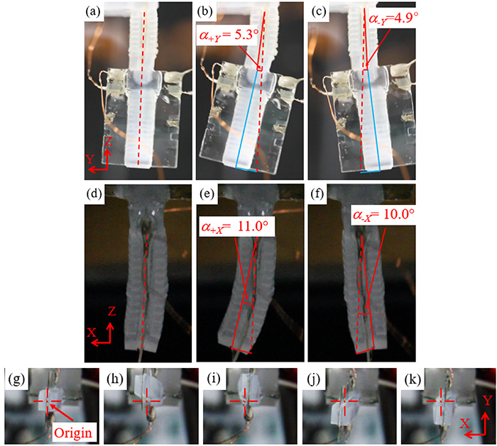
Figure 12. Images of the bent microactuator: (a) initial state without electric field (side view), (b) 1 MA bent in +Y direction (side view), (c) 1 MA bent in −Y direction (side view), (d) initial state without electric field (front view), (e) 2 MA bent in +X direction (front view), (f) 2 MA bent in −X direction (front view), (g) initial state without electric field (bottom view), (h) two-DOF bent in +Y/+X direction (bottom view), (i) two-DOF bent in +Y/−X direction (bottom view), (j) two-DOF bent in −Y/+X direction (bottom view), and (k) two-DOF bent in −Y/−X direction (bottom view).
Download figure:
Standard image High-resolution image4.2. Bending control of the proposed soft microactuator
Another challenge in this work is to realize the proposed microactuator control method. As shown in figure 11(a), only one APS was used to supply two 1-DOF bending microactuator units 1 MA and 2 MA simultaneously. Adjusting the output pressure from the APS affects the bending angles of both 1 MA and 2 MA. To selectively control the bending angle of 1 MA or 2 MA, the pressure difference between the two FERVs of that microactuator need to be adjusted. This can be realized by adjusting the electric field strength in each FERV.
Figure 13(a) shows the non-linear relationships between the bending angles of 1 MA and 2 MA and the applied electric field strengths. When the electric field strength was lower than 1.5 kV mm−1, the bending angles of 1 MA and 2 MA were gradually increased. This is because the electric field's effect is still not strong enough to overcome the torque acting on the nematic liquid crystal molecules due to shear stress. When the electric field strength is higher than 1.5 kV mm−1, the bending angles rapidly increase up to the saturated value approximately at 4.5 kV mm−1. At electric field strength of 5 kV mm−1, the bending angle of 1 MA and 2 MA were slightly increased from 4 kV mm−1.
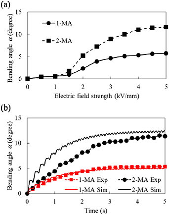
Figure 13. Characteristics of 1 MA and 2 MA: (a) relationship between bending angles and applied electric field strengths, and (b) step-up responses.
Download figure:
Standard image High-resolution imageFigure 13(b) shows the measured step-up responses of 1 MA and 2 MA (1 MA Exp and 2 MA Exp) comparing to the simulation results with the material's Young's modulus of 1.8 MPa (1 MA Sim and 2 MA Sim). The step-up rise times of 1 MA and 2 MA from the measured values are 2.4 s and 2.8 s, respectively, while the step-up rise time from the simulation are 2.3 s for both 1 MA and 2 MA. At the steady state, the simulated bending angles of 1 MA and 2 MA are 5.1° and 12.5°, respectively. The transient state and the steady state of 1 MA is nearly identical to the simulation. However, the response of 2 MA is slightly lower than that of expectation in both transient and steady states. This might be due to the fabrication errors, especially in the bonding process where some of the uncured PDMS used as the adhesive uncontrollably flowed when the device was baked.
4.3. Maximum output force of the proposed soft microactuator
Another essential factor of the multi-DOF soft microactuator that needs to be considered is the output force. Since the proposed soft microactuator has two microactuator units, 1 MA and 2 MA, connected in series and only the base of 1 MA is fixed, the stiffness of 1 MA and 2 MA affects the output force when 1 MA and 2 MA are activated, respectively. In the ideal case, the two-DOF soft microactuator can provide maximum output force if 1 MA and 2 MA are rigid in different directions from the actively bending direction. Despite the fact that 1 MA is flexible in the Y-axis and has high stiffness in the X-axis, it is still not an ideal case and the effect of the stiffness needs to be investigated.
In this section, two experiments were conducted to demonstrate the output force of the fabricated soft microactuator. The 1st experiment was conducted with only 2 MA whose base was fixed and the tip was placed on a digital balance as shown in figure 14(a). Then, the maximum output force of the 2 MA was measured for the electric field strength amplitude of 5 kV mm−1. The measured maximum output force was 7.8 mN.
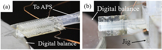
Figure 14. Schematics of output force measurement: (a) measurement of 2 MA, and (b) measurement of two-DOF soft microactuator.
Download figure:
Standard image High-resolution imageThe 2nd experiment was conducted with the fabricated soft microactuator. The base of the soft microactuator was fixed with a metal jig as shown in figure 14(b). The experiment was conducted twice to measure the output force in two directions. The results show the maximum output force at the tip in the Y direction and the X direction were 7.6 mN and 4.1 mN, respectively. As expected, the maximum output force of 2 MA was reduced from 7.8 mN to 4.1 mN due to the elasticity of 1 MA.
4.4. Discussion
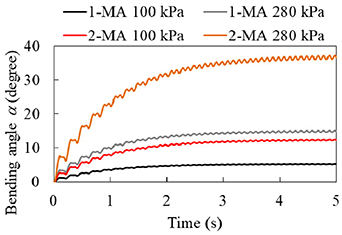
The experimental results demonstrate that the proposed soft microactuator can bend in both the X and the Y directions. The bending angles of 11.0° and 5.3° are the results with the supply peak-to-peak pressure of 100 kPa. These results are under the limit of the APS used in this work. According to the simulation results in figure 15, it is possible to increase the bending angle while maintaining the step-up rise time by increasing the supply pressure for the two-DOF soft microactuator. In order to investigate the maximum pressure that the proposed fluidic soft microactuator part can withstand, air pressure was applied to one of the microactuator chambers until the microactuator broke. The proposed fluidic soft microactuator part could withstand a pressure up to 280 kPa without breakage. Therefore, it would be possible to realize the maximum bending angles of 15° and 36° in the X and Y directions, respectively. These values are thought to be sufficient for the application to be a manipulator on the advanced microrobot.
Figure 15. Simulated step-up responses of 1 MA and 2 MA with different supply pressures.
Download figure:
Standard image High-resolution image
The step-up rise time of the fabricated 1 MA and 2 MA were 2.4 s and 2.8 s, respectively. This result was caused by utilized the optimized chamber's dimension and the FERV's dimension from our previous work [26, 28]. This response is thought to be sufficient for the advanced microrobot for some tasks in which the high response is not the most critical factor. It is possible to improve the response of the proposed microactuator by reducing the flow resistance of the FERVs (see figures S3 and S4 in the supplementary document). However, the bending angle is decreased and the ripple of bending angle is increased. In consideration of the application, the desired design should be employed.
In terms of the maximum output force, the measured maximum output force in the X and Y directions are 4.1 mN and 7.6 mN, respectively. The weight of the fabricated soft microactuator, including the mass of the ERF inside the soft microactuator, is 0.71 mN (72 mgf). The proposed soft microactuator could provide forces of 5.8 and 11 times its weight. Since the weight of a micro camera used in a medical endoscope such as Omnivision OVM6948 can be as low as 8.5 μN (0.87 mgf) [33], the output force of the proposed soft microactuator are ample in both directions. This proves that the output force of the proposed soft microactuator is sufficient for an in-pipe inspection application.
Comparing the proposed soft microactuator to the previous studies [18, 34–36], the maximum bending angles of the proposed soft microactuator is on the lower side. However, the proposed soft microactuator can be used in an in-pipe microrobot and have multiple benefits over the other microactuators such as: (a) the FERV realizes a soft microactuator integrated with microvalves without moving parts, (b) no external control valve is necessary, which minimizes the size of the bending microactuator, (c) the series connection of the bending microactuator units realizes multi-DOF soft microactuator easily, (d) the APS realizes the multi-DOF soft microactuator integrated with FERVs having a compact and simple piping system, and (e) the usage of the APS and the FERVs make it possible to realize closed system deployment, which is ideal for independent microrobots.
5. Conclusions
For advanced microrobots such as an in-pipe working microrobot with dexterous micromanipulators, a novel multi-DOF soft microactuator integrated with FERVs using an APS was proposed and developed. The main results are summarized as follows:
- (a)Novel multi-DOF soft microactuator integrated with FERVs using an APS was proposed. The proposed actuator is a series connection of multiple one-DOF soft microactuator units integrated with FERVs that gives the benefits such as: 1. compact design with built-in FERVs and an alternating pressure system, 2. multi-DOF microactuator with simple structure, and 3. closed system suitable for independent microrobots.
- (b)As a basic module, a 20 mm long two-DOF soft microactuator was designed through simulation. The designed actuator is a combination of one-DOF soft microactuator unit 1 MA at the root and 2 MA at the tip, and the tip displacements were simulated. To equalize the tip displacements in the horizontal and the vertical directions, the length ratio of 1 MA and 2 MA was determined.
- (c)A 20 mm long two-DOF soft microactuator was fabricated using MEMS technologies and characterized experimentally. Through the experiments with several elastic materials, the most suitable materials were selected. Then, 1 MA and 2 MA were fabricated and connected together by the MEMS technologies. The tip displacements, the response and the output forces were measured, and the two-DOF motion was clarified. The improvements of the tip displacements, the output forces and the response were discussed.
Data availability statement
All data that support the findings of this study are included within the article (and any supplementary files).