

Abstract
High-performance flexible pressure sensors are attracting great interest owing to their potential applications for electronic skins, human–machine interfaces, and biomedical diagnostics. However, there remain significant challenges for the fabrication of low-cost and high-sensitivity sensors. Here, we report the preparation of Ti3C2Tx MXene/single-wall carbon nanotube (SWNT) composite films through vacuum-assisted filtration followed by thermal shrinkage. SWNTs can effectively prevent MXenes from stacking and improve the electrical performance of the films. The films are used as a flexible piezoresistive sensor for pressures ranging from 33 Pa to 130 kPa. And experimental test results indicate that the fabricated pressure sensors have high sensitivity (116.15 kPa−1 below 40 kPa and 12.7 kPa−1 at 40–130 kPa), a fast response time of 13 ms, and long-term stability over 6000 periods. The sensor can be used to monitor human physiological signals, such as finger movements, voice detection, and wrist pulse in real-time. Moreover, a 4 × 4 sensor array was successfully applied in the pressure distribution mapping of different objects, indicating that the pressure sensor can be applied in electronic skin, medical devices, and other wearable devices.
Export citation and abstract BibTeX RIS
1. Introduction
In recent years, highly sensitive and flexible pressure sensors are being actively studied owing to their potential applications in wearable electronics [1, 2], healthcare monitoring and diagnosis [3, 4], soft robotics [5], and man–machine interaction [6]. By far, various types of flexible pressure sensors have been designed, including piezoresistive [7, 8], piezoelectric [9, 10], capacitive [11–13], and triboelectric sensors [14, 15]. In particular, piezoresistive sensors transduce external pressure signals into resistance signals, and have several advantages, such as low-cost fabrication, high sensitivity, easy signal detection, fast response, and low energy consumption [16, 17]. Generally, piezoresistive sensors are composed of flexible substrates, sensitive materials, and conductive electrodes. Sensitive materials are the most critical component of flexible pressure sensors and need to meet certain requirements, including mechanical flexibility and bending properties. Although significant progress has been made in piezoresistive sensors, the large-scale preparation of low-cost, high-sensitivity materials still poses huge challenges [18, 19].
MXenes, a newly developed two-dimensional (2D) laminated transition metal carbides or carbonitrides, exhibit distinctive properties such as good hydrophilicity, large specific surface area, and high conductivity [20, 21]. MXenes are mainly prepared by selective etching of 'A' layers from the three-dimensional (3D) MAX phases using hydrofluoric acid (HF) or a mixed solution of hydrochloric acid (HCl) and lithium fluoride (LiF) [22], where M stands for an early transition metal (e.g. Ti, Nb, V, Mo), A represents a III–VI group element (e.g. Al, Si, Ga), and X is C and/or N element. The chemical components of MXenes are normally expressed by the formula Mn +1Xn Tx (n = 1–3), where Tx is the surface termination hydroxyl-(–OH), oxygen-(–O), or fluorine-terminated groups (–F). MXenes have shown promising application prospects in gas detection [23], electromagnetic shielding [24], energy storage [25, 26], and water purification [27]. Generally, MXenes have great potential as sensitive materials for piezoresistive sensors [28]. For example, Li et al [29] produced a flexible piezoresistive pressure sensor by immersing MXene in fabric, with a sensitivity of 12.095 kPa−1 at 29–40 kPa and a rapid response time of 26 ms. Ma et al [30] fabricated a flexible and sensitive piezoresistive sensor based on MXene with greatly changed interlayer distances. The senor shows gauge factor of 180.1 and response time of 30 ms. Cheng et al [31] prepared an MXene-based piezoresistive sensors with randomly distributed spinous microstructures, which showed a relatively short response time (<130 ms) and high sensitivity of 151.4 kPa−1.
However, similar to other 2D materials, the re-stacking of ≈1 nm thin MXenes sheets limits their electrical performance as electrodes [27]. Recent studies have indicated that the introduction of other materials between the plates prevents the accumulation of MXenes. The materials are usually nanoparticles [32], carbon nanotubes (CNTs)/nanowires [33] and graphene. CNTs which have good electronic transport properties and the ability to form nano-network structures, are a suitable choice. The mixing of MXene and CNT not only can enhance the conductivity of the composite material, but also can inhibit layered stacking, making the structure more stable.
In this work, we designed a highly sensitive and flexible piezoresistive sensor based on an MXene/single-wall carbon nanotube (SWNT) composite film. The composite film was prepared via vacuum-assisted filtration (VAF) followed by thermal shrinkage and obtained a crumpled structure to improve the electrical properties of the sensor. The morphology of the piezoresistive sensor was analyzed using scanning electron microscopy (SEM). Taking advantage of a large specific surface area of MXene and the electrical properties of SWNT, the pressure sensor can be used for broad-range measurements and has a fast response speed. Practically, the pressure sensor can detect human activity including wrist pulse, voice detection and joints bending. Besides, we also made a sensor array for mapping the pressure distribution. To the best of our knowledge, this work is the first demonstration that a thin film was formed into a crumpled structure to make sensitive materials of a piezoresistive sensor. The facile, low-cost, scalable, and sustainable fabrication strategies provide new insights into the development of green electronics. The highly sensitive sensor has potential applications in healthcare, human–machine interfacing, and electronic skins as wearable electronics.
2. Results
2.1. Preparation of S-MXene film
2D Ti3C2Tx MXene was produced by selective etching the Al layer from Ti3AlC2 with HCl and LiF solutions. The Tyndall effect (figure 2(f)) proved that SWNT, MXene, and S-MXene nanosheets can well dispersed in aqueous without surfactant, indicating their good dispersion property, which is beneficial for preparing uniform films. The Raman spectra (figure 2(e)) also proved the successful synthesis of Ti3C2Tx .
Owing to the unique features of ultrathin sheets, MXenes can be easily assembled to form films through vacuum-assisted filtration. To enhance the electrical performance and make it easier to form a film, the MXene dispersion was mixed with pure SWNTs solution (figure 1(a)), then poly(vinyl alcohol) (PVA) was added into the SWNT-MXene dispersion as an activator. The optimized composition for the piezoresistive layer was set to 10 wt.% PVA, 45 wt.% SWNTs, and 45 wt.% MXene. A planar SWNT-MXene film (abbreviated as S-MXene in this paper) was obtained via VAF and fully rinsed with DI water to remove the PVA foam. The cross-sectional (figures 2(c) and (d)) and top-down SEM images (figures 2(a) and (b)) indicated that SWNTs were interconnected and uniformly distributed in the multilayered S-MXene film, and the thickness of the flexible S-MXene film is approximately 2 μm.
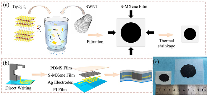
Figure 1. Schematics illustrating the preparation process of the piezoresistive sensor. (a) The preparation of S-MXene film by VAF and thermal shrinkage. (b) Design and assembly of a piezoresistive sensor. (c) Comparison of S-MXene film before and after thermal shrinkage.
Download figure:
Standard image High-resolution image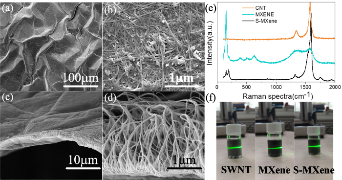
Figure 2. Characterizations of S-MXene film. (a) SEM image of S-MXene film with crumpled structure (scale bar 100 μm). (b) Enlarged image of (a) (scale bar, 1 μm). (c, d) Cross-sectional SEM image of S-MXene film with an interlocked interface. (e) Raman spectra of the SWNT, MXene and S-MXene powder. (f) Tyndall effects of SWNT, MXene, and S-MXene dispersion, respectively.
Download figure:
Standard image High-resolution imageThen, the planar S-MXene film was detached from the hydrophobic polyvinylidene fluoride (PVDF) filter film by immersing it in ethanol, and then carefully transferred to the plasma-treated polystyrene (PS) film (i.e. shrink film). After natural drying, the S-MXene film was used for thermal shrinkage.
The planar S-MXene sample was placed in a vacuum drying oven for vacuuming and heated above 135 °C for 15 min. The sample was shrunk to half of its original length and a quarter of the original area (figure 1(c)). The biaxial contraction brought about the deformation of a planar structure into a crumpled structure. In this process, the thermal shrinkage must be performed lower than 140 °C to avoid the potential oxidation of MXene. After thermal shrinkage, the shrink film was dissolved in an organic solvent, and the S-MXene film was transferred into ethanol. It should be mentioned that the independent S-MXene film in the ethanol still maintained the crumpled structure.
2.2. Fabrication of the pressure sensor
First, a polyimide (PI) film with appropriate size was prepared. The PI film was washed three times with acetone, ethanol and DI water in sequence. After drying the film following 5 min of hydrophilic treatment in the oxygen plasma cleaner. The interdigital electrodes were printed using a Microplotter II direct writing system (SonoPlot company). By controlling an ultrasonicated dispenser to guide the nanosilver particle ink directly, the electrodes could be easily printed out as predefined interdigital patterns. The direct writing process is schematically illustrated in figure 1(b), the solution was continuously released from the needle by vibration and deposited on the substrate with the micropipette moving along a predefined path. After a 10 min heat-treatment of the silver ink at 140 °C, the electrodes were completed. The distance between two neighboring interdigital electrodes was approximately 0.5 mm. Compared with other fabrication techniques, direct writing technology has the advantages of high precision and easy operation.
The sensor was prepared by sandwiching an S-MXene film between the interdigital electrodes and the insulation layer. In brief, the S-MXene film was transferred to the PI film in ethanol. After drying, the copper conductive tapes were connected to both ends of the interdigital electrodes. A piece of flexible and transparent polydimethylsiloxane (PDMS) thin film was put as the insulation layer to prevent the S-MXene film from falling out from the substrate.
2.3. Analysis on working mechanism of the sensor
An equivalent circuit model was established to explain the working mechanism of the piezoresistive sensor, as shown in figure 3(a). The total resistance (Rtotal) of the sensor could be simply defined as:

Figure 3. (a) The equivalent circuit diagram of the pressure sensor. (b) Comparison of response time and maximum detection pressure between our sensor and previously reported pressure sensors [34–38]. (c) The schematic diagram of sensor working mechanism.
Download figure:
Standard image High-resolution imagewhere Rf is the resistance of the S-MXene film electrode, and Rc is the contact resistance between the interdigital electrodes and the S-MXene film [39]. Figure 3(c) shows the working mechanism of the sensor. Upon application of compressive strain to the sensor, the distance between the MXene layers will be reduced and overlap with each other to form a tunnel junction, the electrons can easily tunnel through the nano-layer, which reduces the resistance and further increases the current flowing through the device [40]. As shown in figure 3(c), the SWNTs in the sensing unit are more likely to contact each other to form new conductive paths, and the contact area between the S-MXene film and interdigital electrodes increases in response to small external pressure (less than 40 kPa), leading to a decrease in Rc and an increase in current. As the pressure continues to increase (40–130 kPa), the rate of increase in the contact area between MXene and electrodes gradually reduces, causing the saturation of the sensitivity.
2.4. The properties of the piezoresistive sensor
To evaluate the performances of our pressure sensor, a high-precision pressure test platform (including pressure generator, an electrical signal detecting device, and a computer for collecting electrical signals) was used to test the characteristics of the relevant pressure sensor. The test system was capable of measuring the output signal changes at different levels of pressure under a voltage of 1 V in real-time.
In general, the sensor's sensitivity S is defined as follows:

where I0 and ΔI denote the initial current and the relative change in current (I–I0), respectively, ΔP denotes the pressure change applied to the sensor. As shown in figure 4(a), the I/I0 increased sharply until 40 kPa and then increased slightly between 40 and 130 kPa; the corresponding sensitivity values are 116.15 kPa−1 and 12.7 kPa−1, respectively. The curve indicates the remarkable linear response of the S-MXene based sensor under the corresponding pressure with an ultralow detection of 33 Pa and an ultimate pressure of 130 kPa.

Figure 4. Electromechanical performance of the pressure sensor. (a) Change in current with respect to increased pressure ranging from 33 Pa to 130 kPa. (b) I–V curves of the sensor with various constant pressures applied. (c) Response and recovery time of the sensor under 13.5 kPa. (d) I–T curves under five levels of pressure. (e) The excellent cycle stability tests for 6000 cycles.
Download figure:
Standard image High-resolution imageFigure 4(b) shows the linear I–V relationship with the voltage varying from −1 to 1 V, indicates that an excellent ohmic contact was formed between the S-MXene film and the interdigital electrodes. The slope of the I–V curve increases as the pressure increases, suggesting that the resistivity of the sensor is continuously decreasing.
Table 1. Comparison of sensitivity with other sensors [29, 41–45].
| Sensitive materials | Structure | Sensitivity (%) | Applications | Ref. |
| CNTs | 3D network | 96.8 kPa−1 | Facial expressing | [41] |
| MXene | Textile | 12.095 kPa−1 | Throat swallowing | [29] |
| PDMS/carbon black | Film | 43 kPa−1 | LED switch | [42] |
| MWCNTs | Microplate | 7.7 kPa−1 | Immunoassay of CEA | [43] |
| AgNWs | Microarray | 29.4 kPa−1 | Voice vibrations | [44] |
| PANI/BC/CH | Aerogel | 1.41 kPa−1 | Joint movement | [45] |
| MXene/SWNT | Film | 114 kPa−1 | Pulse recognition | Our work |
A fast response pressure sensor can accurately distinguish pressure changes in real-time. Figure 4(c) and its insets show the response times of applying and relaxing pressure for the sensor. The response and recovery time of the sensor are 13 ms and 25 ms under 13.5 kPa, respectively, which was obviously better than most sensors reported in other articles (figure 3(b)).
Figure 4(d) shows a series of I–T curves of the sensor under different pressures, indicating that the current monotonically rises with the increasing pressure. Therefore, the sensor can easily distinguish the intensity of the external pressure by determining the magnitude of the current.
To further evaluate the mechanical stability and durability, the sensor was measured by repeatedly loading the pressure cycle under 50 kPa for 6000 periods, as shown in figure 4(e), the output current of the sensor experiences very small fluctuations. At the same time, the enlarged insets clearly show that the amplitudes of the start and end points are almost the same, which proves the outstanding stability of the sensor [46].
2.5. Applications of the sensor for human's activities
The flexibility, high sensitivity and high stability of the pressure sensor make it a huge potential application in electronic skin and real-time monitoring of human activities. To fully exploit the fast response and high sensitivity, the sensor was attached to the human body as wearable devices to monitor the physiological signals toward different application scenarios. As shown in figure 5(a), one sensor was mounted around the throat of a volunteer to detect words with different syllables. From the figure, it can be seen that the I–T curve fluctuates quite differently when different words were uttered. When the same words were uttered, different tones corresponded to different curve heights, but the waveforms were similar. When a volunteer uttered a word with two syllables (e.g. 'sensor'), a waveform with double peaks was repeatedly observed. When the volunteer uttered the trisyllable word 'family,' a regular waveform with three distinct peaks was observed. The difference in the pronunciation of words is reflected in the intensity changes of the wave crests, which indicates that the sensor has the potential for speech recognition.
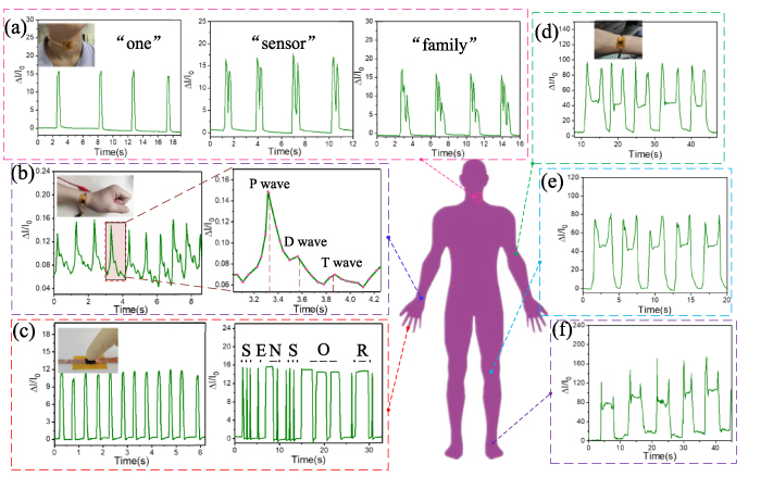
Figure 5. Applications of the pressure sensor based on S-MXene film. (a) Current changes when the wearer spoke 'one', 'sensor' and 'family.' (b)Real-time recording of the wrist pulse with a frequency of 9 beats in 8 s and an enlarged view of the pulse wave including P-wave, T-wave, and D-wave. (c) Responsive curves arising from finger touching and Morse code test. (d–f) Signal responses in current changes come from elbow bending, knee bending and ankle bending, respectively.
Download figure:
Standard image High-resolution imageThe pulse wave signal contains physiological information including heart rhythm, cardiovascular status, and arteriosclerosis, which can provide a reference for the prevention of cardiovascular diseases. The inset of figure 4(b) shows that the sensor was attached to the wrist to monitor the arterial pulse condition of the human body and the sensor detected that the subject's pulse was 70 beats min−1. The three distinguishable peaks with 'P' (percussion), 'T' (tidal), and 'D' (dicrotic) waveforms clearly confirmed the fast response and high sensitivity of the sensor. These results indicate that the sensor can accurately record real-time pulse fluctuations and display clear and identifiable waveforms. Thus, the sensor is suitable for disease diagnosis and medical monitoring.
As shown in figure 5(c), the sensor can clearly recognize the time interval and strength of finger taps, repeated waveforms are observed under the same tapping action. In addition, by touching the surface of the pressure sensor to input the Morse code, the current-response sensing curve represents the output of the corresponding character (e.g. 'sensor').
Besides, the pressure sensor can produce deformation when the joints are repeatedly bent, resulting in repeated changes in the current signal. For example, we can monitor small changes in the forearm (figure 5(d)), knee (figure 5(e)) and ankle (figure 5(f)) contractions, and different peak intensities on the I–T curve corresponding to various joint or muscle movements.
Furthermore, a flexible sensor array of 16 pixels (4 × 4 units) based on the S-MXene film was designed to explore the potential applications in the field of wearable electronics and man–machine interactions. The sensor array using direct writing technology to detect the pressure distribution as shown in figure 6, nanosilver circuits were deposited onto a PI film substrate. The circuits were attached by 16 rectangular samples of S-MXene film of the same size using adhesives. Then a transparent PDMS film was fixed on the top of each composite film. As shown in figure 6(b), a U-shaped magnet and a heavier weight were placed on the surface of the sensor array at the same time, and the 3D histogram recorded the current changes of the corresponding pixels. The contrast mapping was consistent with the position and pressure distribution of the objects. Therefore, the current intensity at each matrix point can be used as an indicator of the weight or pressure distribution. This pressure sensor array demonstrates a promising potential for applications in multitouch devices and human–machine interaction of smart devices.

Figure 6. (a) A 4 × 4 sensor array and circuit diagram. (b) Top view of the sensor array with a magnet (50 g) and weight (100 g) applied and the corresponding pressure distribution.
Download figure:
Standard image High-resolution image
3. Conclusions
We prepared a piezoresistive pressure sensor with high flexibility based on MXene/SWNT films. The composite film was prepared by VAF and thermal shrinkage to form a crumpled structure. Importantly, the crumpled structure causes an increase in the distance between electrodes and sensing material, which improves the performance of the pressure sensor. The sensor showed a high sensitivity of 116.15 kPa−1 below 40 kPa and 12.7 kPa−1 at 40–130 kPa, a fast response time of 13 ms, a small pressure detection limit of 33 Pa and ultrahigh detection limit of 130 kPa, and excellent stability over 6000 cycles. The pressure sensor can be applied for monitoring human activities in real-time including pulse wave, voice recognition, finger touching, and wrist bending, and for the quantitative evaluation of the pressure distribution.
4. Experimental
4.1. Materials
Ti3AlC2 powders (MAX, Tongrun Info Technology Co. Ltd, China), LiF (Sigma-Aldrich, >99.9%), HCl (Sigma-Aldrich, >99.9%), SWNTs (Nanjing XFNANO Materials Tech Co., Ltd), PVA powder (Mw 67000, Sigma-Aldrich) and dichloromethane (DCM) solution (J.T. Baker, 99.9%), transparent PS shrink films were purchased from Grafix. Milli-Q water (18.2 MΩ, resistivity) was used for all solution preparations.
4.2. Preparation of the MXene (Ti3C2Tx ) dispersion
Ti3C2Tx Mxene nanosheets were synthesized by selective etching of Al atomic layers from Ti3AlC2 [47]. One gram of LiF was added to 6.0 M HCl solution (20 ml), 1.0 g of Ti3AlC2 MAX phase was slowly added into the solution under vigorous stirring, then the mixture was kept at 35 °C for 24 h. After etching, the mixture was washed with DI water for several times until the pH value was about 7.0. Subsequently, the washed sediment was added into 100 ml of DI water, manual shaking for 5 min to delaminate the Ti3C2Tx nanosheets, and the solution was centrifuged at 3500 rpm for 30 min. The supernatant was used to make thin films (40 nm) of Ti3C2Tx MXene nanosheets, and the concentration of MXene suspension was about 2.7 mg ml−1.
4.3. Preparation of SWNT and PVA dispersion
The SWNT powder and PVA powder was added to DI water respectively to obtain a SWNT and PVA dispersion, then the solution was sonicated for 2 h. The concentration of the SWNT and PVA dispersion are 0.1 mg ml−1 and 0.05 mg ml−1, respectively.
4.4. Fabrication of S-MXene composite film
First, the MXene, PVA and SWNT dispersions were mixed uniformly and sonicated for 10 min. Then, the well-dispersed mixture (solid content 1 mg, MXene: SWNT: PVA = 9:9:2) was added to the vacuum filtration system with PVDF filter membrane. After all the liquid was filtered, DI water was used to remove the PVA particles in the S-MXene film. After drying at room temperature, the S-MXene film was immersed in ethanol to separate it from the PVDF filter membrane and then stored in ethanol.
4.5. Fabrication of S-MXene film with crumpled structure
The PS shrink film was cut into 5 cm × 5 cm squares, washed with absolute ethanol and DI water in sequence. The substrate was placed in a vacuum plasma cleaner and treated with oxygen plasma for 10 min. Then, S-MXene film was carefully transferred onto the PS film, after being air-dried, the planar S-MXene film was obtained, and the sample was placed in a vacuum drying oven at 135 °C (higher than the glass transition temperature of PS (≈100 °C)) for 15 min. After that, the sample was taken out of the oven and cooled down to obtain the sample with a shrunk area of approximately 2.5 cm × 2.5 cm. Afterward, the shrunk sample was immersed in DCM to dissolve the PS substrate, and the independent S-MXene film was washed twice with DCM to remove the remaining PS particles, and finally washed with ethanol.
4.6. Characterization and measurements
The morphology images of S-MXene film was obtained by high-resolution scanning electron microscope (SEM, Hitachi S-4800, 5 kV). XRD and Raman spectra of MXene and S-MXene were carried out using x-ray diffractometer (Dandong, DX 2700) and Raman Spectrometer (Horiba Jobin Yvon Aramis, 532 nm laser), respectively. In this experiment, the performance of the sensor was tested on a system with a computer-controlled single-axis motor, a dynamometer, and a high-precision multimeter (Keithley 2002). Response time was measured by LCR meter (IM3536, HIOKI).
Acknowledgments
This work was supported by National Key R&D Program of China (Grant No. 2018YFB2003100), National Natural Science Foundation of China (Grant No. 51875534), the Outstanding Young Talents Support Plan of Shanxi province, the Young Sanjin Scholar Distinguished Professor Plan of Shanxi Province, the Innovative Research Group Project of National Natural Science Foundation of China (Grant No. 51821003), and the Shanxi '1331 project' keys subjects Construction.