

Abstract
Location of polyethylene utility pipes is improved by installing electromagnetic targets with the pipe. A new electromagnetic target could be created by impregnating polyethylene with conductive materials to impart it with electromagnetic properties necessary for use in utility location. Antennas created from this conductive polyethylene composite could be molded directly to the pipe during fabrication. The addition of high concentrations of conductive fillers into the material alters the mechanical performance of the material in addition to the electromagnetic properties, resulting in a material which displays brittle behavior, unlike neat polyethylene. Both electromagnetic and mechanical properties of the material are characterized to predict the behavior of the conductive polyethylene in service. In a layered composite with unmodified polyethylene and conductive polyethylene layers, the brittle behavior of the conductive polyethylene limits the strain to failure of the overall composite.
Export citation and abstract BibTeX RIS
1. Introduction
Modern utilities pipes are commonly made from thermoplastics like polyethylene for improved environmental stability relative to traditional steel or cast iron pipe. However, the electromagnetic properties of polyethylene are incompatible with traditional utilities location methods, which use disturbances in induced electromagnetic fields for sensing [1]. Instead, ground penetrating radar (GPR) is a common method for location of polyethylene pipe. During a GPR survey, a radar signal is sent into the ground in the area of interest, which is reflected by the differences in dielectric properties between adjacent materials. A radar receiver at the surface records the reflected signals, and a trained operator interprets the results. Frequency ranges and other parameters for GPR surveys are chosen based upon the size and depth of the target of interest. Generally, lower frequency GPR signals can penetrate farther into the earth but have lower spatial resolution. Utility pipes such as natural gas distribution lines can have nominal diameters as small as 1" and be buried with a minimum depth of 12", so high frequencies, in the range of 0.1–3 GHz, are used for utility location [2–4].
Interpretation of the GPR survey results is critical to the effectiveness of this method, and a skilled operator is necessary to distinguish targets of interest from background reflections. The signals from polyethylene pipes are often small in magnitude and can be difficult to identify, especially in areas with cluttered radar signals, such as locations where other utilities are installed or areas with rocks and tree roots. High loss soils, like those with high clay content, can also increase the difficulty in determining an accurate location [5, 6].
To improve location of pipes, federal code requires that polyethylene pipes be installed with electromagnetic targets which amplify the radar signal, the most common of which are tracer wires [7]. During location, a current is sent through this continuous wire, which induces an electromagnetic field to aid detection. However, tracer wires can shift away from the pipes or break underground, which reduces the effectiveness of the wires [8]. Improperly located pipes are often damaged during construction or maintenance projects, endangering operators and surroundings and necessitating expensive repairs. Damage caused by equipment strikes is the most common cause of failure for oil and gas industry pipelines [9].
An alternative electromagnetic target could be created from polyethylene modified to be electromagnetically responsive. Polyethylene compounded with conductive fillers becomes a conductive composite with electromagnetic properties more suited for detection. The resulting material can be used to manufacture antennas designed to respond when interrogated with radar signals. Antennas made from modified polyethylene could be molded to the pipes during fabrication, reducing the need for separate installation of electromagnetic targets. Additionally, discrete antennas do not require a continuous electrical connection and surface access like other electromagnetic targets such as tracer wires.
When creating the composite material to be used for the antennas, the quantities of filler materials should be optimized so the composite has favorable electromagnetic properties. The efficiency of an antenna increases as the resistance of the antenna material decreases, as the amount of energy lost to heat within the antenna is minimized. The behavior of conductive fillers within a matrix can be described with percolation theory. Conductive fillers in a matrix have a percolation limit, at which point a network of filler particles has been established through the matrix, and additional filler will not continue to raise the conductivity of the composite [10–12].
Carbon black is commonly used as a conductive filler in thermoplastics due to its economy and ease of compounding. The point at which percolation occurs is dependent upon the size and aspect ratio of the filler particles. Previous studies have shown that percolation of carbon fillers in polyethylene occurs between 5% and 40% [13–15]. Conductivity of a composite can be increased beyond percolation through the addition of a second filler with a different aspect ratio, which can bridge areas of high conductivity and create new conductive networks. The second filler is commonly carbon based, such as carbon nanotubes or carbon fibers, though these materials have lower conductivities than metal fillers such as aluminum [16–18]. This third phase will also have a percolation limit within the composite [18–21]. A second method for increasing the conductivity of a composite is by compounding in an additional material, typically a polymer which does not blend with the original matrix, into the composite. When this second material is present, the conductive filler will become concentrated in either the first matrix phase or the interface between the two phases, increasing the concentration of the filler through the matrix without increasing the percentage of the filler in the composite [12, 20].
Previous work has shown that the addition of high concentrations of filler materials into the polyethylene will alter the mechanical properties of the composite material as well as its electromagnetic properties. Polyethylene compounded with carbon black often displays increased stiffness but lower strains-to-failure than unmodified polyethylene [12, 13, 22–25].
Antennas molded to pipes prior to installation will experience the same strains as the pipes during service. Characterization of the effects of the filler on the mechanical properties of the composite is important to determine if the antenna materials will survive the physical deformations applied to a pipe in service.
Polyethylene pipes are manufactured through extrusion, and then pipes with diameters of 6" or less are coiled onto spools for storage and transportation [26]. Because polyethylene has high ductility, the majority of pipe bending is done through cold working in the field [27]. Coiling and straightening, as well as the process of installation, introduces strains in the polyethylene pipe. Polyethylene pipe can often achieve strains of 25–30% before local buckling occurs, though in practice is often limited to deformations of 7.5% or less for safety [27, 28].
In this work, a composite polyethylene with electromagnetic properties necessary for detection with commercial GPR equipment is processed and characterized. Because the conductive polyethylene is intended to be bonded to polyethylene pipe in service, the behavior of the layered structure is also studied. Antennas produced from the conductive polyethylene are used to aid detection of a buried thermoplastic pipe.
2. Methods
2.1. Materials and processing
High density polyethylene (HDPE) pellet was purchased from Premier Plastic Resins, a commercial supplier, and used as received. Conductive carbon black, with an average particle size of 30 nm, was purchased from Asbury Carbons, a commercial supplier. Aluminum flake, acquired from Transmet Corporation, has an average area of 1.61 ± 0.51 mm2 and an average thickness of 0.038 ± 0.007 mm. To create conductive composite polyethylene, additives of varying percentages by volume were compounded into polyethylene in a Banbury mixer and mixed for fifteen minutes at a temperature of 160 °C until the fillers were distributed through the matrix.
2.2. Electromagnetic property characterization
Resistivity was measured for conductive polyethylene specimens with increasing amounts of fillers. Specimens containing up to 25% of carbon black and 20% aluminum by volume were produced. Four-point resistance of these specimens was measured according to the procedure presented in ASTM Standard D 4496 [29]. Specimens were measured in the plane of the material and through the thickness of the material to determine if the compression molding process resulted in anisotropy in the resistivity material.
2.3. Mechanical property characterization
Dogbone specimens were manufactured from unmodified polyethylene, polyethylene compounded with 15% carbon black by volume, and polyethylene compounded with 15% carbon flake and 10% aluminum flake by volume. A conductive polyethylene antenna molded to a polyethylene utility pipe was simulated with bilayer specimens consisting of a conductive polyethylene layer molded to an unmodified polyethylene substrate. A heated hydraulic press was used to mold plates of conductive polyethylene to plates of unmodified polyethylene, as shown in figure 1(a). The resulting bilayer polyethylene plate was molded to the desired thickness using aluminum spacers on the same hot press. Dogbone specimens of single materials and the bilayer polyethylene were cut to dimensions according to ASTM Standard D 638 [30]. Tensile testing was performed with a uniform speed of 0.005 mm s−1. For the bilayer polyethylene, wires were molded into the specimens to serve as electrodes for measuring the change in electrical properties due to increasing strains on the specimens. A schematic of the bilayer resistance test can be seen in figure 1(b).
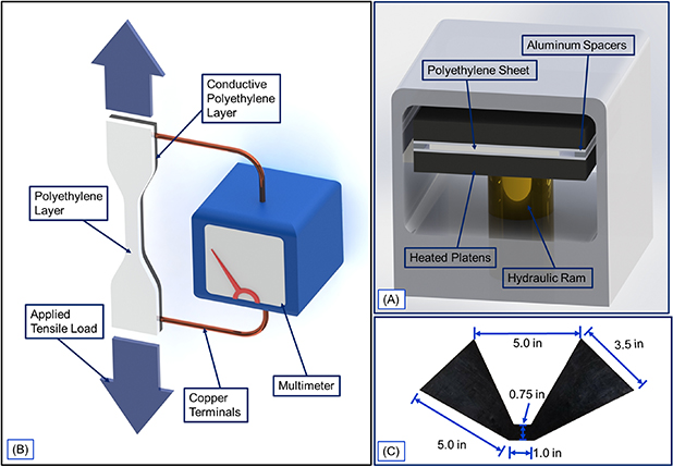
Figure 1. (a) Schematic of a bilayer tensile specimen consisting of a conductive polyethylene layer molded to a neat polyethylene layer. Resistance across the specimen is measured continuously during the tensile test. (B) Tensile specimens are manufactured by laminating different polyethylenes using a heated hydraulic press. (c) Dimensioned image of a cross-polarized polyethylene bowtie used in GPR surveys.
Download figure:
Standard image High-resolution image2.4. Measurement of pipe strain
A test fixture was constructed to measure the strains that a typical polyethylene pipe would experience in service. A 1" polyethylene pipe with dimension ratio 11, representing a standard distribution line, was bent over a mandrel to industry-standard minimum bend radii for both short and long term bending. On a pipe in bending, the location of the highest strain will exist on the outermost point on the pipe, which is the farthest away from the neutral axis and therefore undergoes the most deflection. Strain at the outermost point of a pipe during bending to radii of 32", 23.5", and 17" was measured with digital image correlation [31].
2.5. Conductive polyethylene antennas
To test the performance of antennas made from the conductive polyethylene, cross-polarized bowtie antennas were cut from compression molded sheets of conductive polyethylenes using a 50 W laser cutter. The bowtie shape was chosen for ease of manufacturing and a wider bandwidth than similarly sized dipoles. Because the lobes of the antenna are cross-polarized, the response of the antenna to GPR is less dependent on the orientation of the antenna within the pipe. One manufactured antenna can be seen in figure 1(c). After manufacturing, the antennas were molded to sheets of polyethylene to simulate an antenna molded to a polyethylene utility pipe.
The performance characteristics of an antenna are dependent upon the properties of its surroundings [32]. Antennas intended for utility location should therefore be tested in conditions similar to those that would be expected in service. An underground testbed was constructed by burying a 8" PVC pipe to a standard coverage depth of 18". During testing, a nylon line running through a conduit was used to pull an antenna into the underground pipe. To conduct a radar survey of the area, the GPR transmitter (GSSI-SIR-3000 with a 200 MHz antenna) was moved in a straight line perpendicular to the direction of the pipe and a B-scan of the area was collected. RMS amplitude of the radar response was analyzed to determine the percentage of the radar signal above a noise threshold. The radar signal of an antenna with 5% carbon black, with a lower conductivity, and an antenna containing 15% carbon black and 10% aluminum, with a higher conductivity, were compared to the signal of an empty pipe.
3. Results and discussion
3.1. Electromagnetic property characterization
Polyethylene containing only aluminum flake as a filler was not conductive at any measured concentration level because the large flakes were unable to form a continuous conductive path through the polyethylene matrix. Measured resistivities of conductive polyethylene containing only carbon black, shown in figure 2(a), indicate that percolation for this carbon black in polyethylene occurs at around 15% by volume, and the inclusion of additional carbon black in the composite does not result in further reduction of resistivity. Resistivity for composite polyethylenes with only carbon black as a filler material was isotropic when measured in the plane of the material and through the thickness of the material.

Figure 2. (a) Average resistivity of conductive polyethylene containing increasing amounts of carbon black as filler. (b) Resistivity of conductive polyethylene containing 5% carbon black and increasing amounts of aluminum as fillers. (c) Schematic of resistivity measurements. (d) Cross-section of conductive polyethylene with both carbon black and aluminum.
Download figure:
Standard image High-resolution imageMeasured resistivities of specimens with both carbon black and aluminum are shown in figure 2(b). For the specimens without aluminum flake, no significant difference exists between the resistivity measured through the length of the material and the resistivity measured through the thickness, as shown by the schematic in figure 2(c). For composites with aluminum flake, average resistivity measured through the length of the material is often an order of magnitude lower than resistivity measured through the thickness of the material. Previous studies have reported similar differences in the resistivity of the material when measured in plane or through thickness due to alignment of fillers [21]. In the plane of the material, percolation of the aluminum flake within the conductive polyethylene matrix occurs at 5% loading by volume. However, when resistance is measured through the thickness of the material, the aluminum flake does not reach percolation until 10% by volume and has higher scatter. Examination of cross sections of the specimens reveals that aluminum flakes in the material became aligned with the plane of the material during compression molding, as seen in figure 2(d), resulting in the anisotropy in material resistivity.
3.2. Mechanical property characterization
Representative stress-strain curves and typical failure behavior for the individual materials and bilayer specimens is shown in figure 3. Neat polyethylene can draw to several times its own length under tension and exhibits an extremely ductile fracture surface, shown in figure 3(c). The high concentrations of filler materials in the conductive polyethylene, which increase the stiffness of the material, restrict its ability to draw, resulting in brittle failure behavior at much lower strains. The brittle fracture surface of a conductive polyethylene specimens can be seen in figure 3(b). In the bilayer specimens, composed of conductive polyethylene molded to unmodified polyethylene, brittle fracture which begins in the doped polyethylene layer can propagate quickly into the neat polyethylene layer, resulting in brittle failure through the cross sectional area of the specimen. The sharp decrease in the bilayer curve in the stress in figure 3(a) represents the point at which brittle fracture occurs and propagates through the cross sectional area of the specimen. Some tendrils of neat polyethylene remain, however, and drawing of these tendrils is shown in the gradual decrease in the stress after the initial brittle fracture, though these tendrils are small and will only draw for short displacements before fracture. Evidence of this behavior can be seen in the fracture surfaces of the bilayer specimens, as in figures 3(d) and (e).

Figure 3. (a) Stress–strain graphs for conductive polyethylene, unmodified polyethylene, and bilayer specimens. (b) Fracture behavior of conductive polyethylene. (c) Fracture behavior of unmodified polyethylene. (d) Fracture behavior of the unmodified layer of polyethylene in a bilayer specimen. (e) Fracture behavior of the conductive layer of polyethylene in a bilayer specimen.
Download figure:
Standard image High-resolution imageExperimentally measured elastic modulus for all specimens is shown in figure 4(a). The presence of carbon black and aluminum, two stiff materials, in the conductive polyethylene resulted in an increase in stiffness. As the amount of aluminum flake in the composite increased, the stiffness of the material did not increase, but the amount of scatter within each dataset did, indicating that the aluminum flake within the material can act as void content rather than reinforcement due to the materials not effectively bonding. The bilayer specimens had a lower effective modulus than any of the single material specimens.
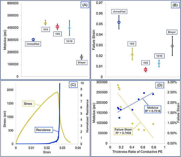
Figure 4. (a) Elastic modulus for neat polyethylene specimens, specimens with 15% carbon black, 15% carbon black and 5% aluminum flake, 15% carbon black and 10% aluminum flake, and bilayer specimens. (b) Failure strain for neat polyethylene specimens, specimens with 15% carbon black, 15% carbon black and 5% aluminum flake, 15% carbon black and 10% aluminum flake, and bilayer specimens. (c) Plot of stress vs strain and normalized change in resistance vs strain for a representative bilayer specimen. (d) Failure strain and elastic modulus for all bilayer specimens vs the relative thickness of the conductive polyethylene layer.
Download figure:
Standard image High-resolution imageFailure strains for all tested specimens are shown in figure 4(b). Failure strain data is critical for industry use, because field practices for installation of polyethylene pipe rely on physical dimensions that are safe for the pipes, but load measurements are not taken during this time. Typically, the failure strain for any material is defined at fracture, but because pipes used in industry are limited to strains below drawing, failure strain for this study was taken at the onset of drawing within the polyethylene. As expected from the failure behavior, adding such high quantities of carbon black to the composite results in a brittle material with much lower strain-to-failure than the neat polyethylene.
For each bilayer specimen, the resistance of the specimen between the grip sections was measured during tensile testing. Stress and normalized change in resistance were both plotted with strain. A representative graph of this data be seen in figure 4(c). The sharp decrease in the magnitude of the stress occurs when the crack propagates through the doped layer and most of the neat polyethylene layer. The following gradual decrease in magnitude shows drawing in the remaining polyethylene tendrils after initial separation. The initial change in resistance occurs at the sharp decrease in stress, which corresponds with the initial specimen separation. The sharp increase in resistance represents the point at which the two ends of the specimen became completely separated.
For this dataset, the average difference in displacement between the initial separation and the loss of electrical contact is less than the average length of an aluminum flake. It is likely that aluminum flakes bridge the two sides of the specimen for a short distance before being pulled out of one side of the doped polyethylene matrix.
Strain to failure for the bilayer specimens showed large variance due to the relative thickness of each of the layers. Figure 4(d) shows the modulus and failure strain for each bilayer specimen compared to the relative thickness of the conductive polyethylene layer in that specimen. For instance, a specimen with equal layers of conductive and neat polyethylene would have a thickness ratio of 0.5. As seen in figure 4(d), both elastic modulus and failure strain were dependent on the thickness ratio of the conductive polyethylene layer. As the thickness of the conductive polyethylene increases, the effective modulus of the composite increases, but the strain before fracture of the composite decreases because the conductive polyethylene layer limits the strains that the composite specimen can attain.
3.3. Fracture surface examination
Fracture surfaces of the conductive polyethylene specimens, as shown in figure 5(a), were imaged with a scanning electron microscope. Figure 5(b) shows a high magnification image of the interface between the conductive and unmodified polyethylene layers. At high magnification, the unmodified polyethylene shows evidence of more ductile behavior in the fracture surface than does the conductive polyethylene, which appears more brittle, with shorter tendrils. Though the two materials exhibit visually different behavior when examined at high magnification, the two materials appear to be well bonded across the entire width of the specimen. The bond between the materials allows for fracture to propagate through the specimens.
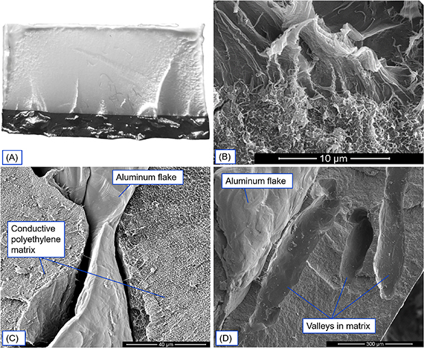
Figure 5. (a) Fracture surface of bilayer polyethylene specimen. (b) SEM image of bilayer specimen fracture surface at the interface between unmodified polyethylene (top of image) and conductive polyethylene (bottom of image). (c) SEM image on an aluminum flake (center) inside a conductive polyethylene matrix (left and right). (d) SEM image of a void in a conductive polyethylene matrix where an aluminum flake has been pulled out.
Download figure:
Standard image High-resolution imageFigure 5(c) shows gaps between an aluminum flake and the surrounding polyethylene. Figure 5(d) shows valleys in the fracture surface where aluminum flakes were pulled out of the polyethylene matrix during tensile testing. The lack of bonding between the aluminum flakes and the polyethylene matrix contributes to the increased variance in material properties as the percentage of aluminum flake in the filler increases. These gaps are likely formed during the cooling process due to the differences in the coefficients of thermal expansion of the two materials. These gaps have previously been reported in studies of aluminum and polymer composites [33].
3.4. Measurement of pipe strain
In industry, polyethylene pipes are classified by their dimension ratio (DR), the ratio of the outside diameter of the pipe divided by the wall thickness [34]. A smaller DR represents a higher wall thickness, and thus a higher pressure rating. A pipe with a higher DR can be bent to a tighter radius of curvature because the thicker wall reduces the tendency of the pipe to kink during bending. Because polyethylene has such high ductility, a pipe can often be bent to a tighter bend radius for short periods of time, such as during transportation or installation. A standard distribution line with DR 11 has a long term minimum bend radius of 32" but can be brought to a bending radius as small as 17" during short term usage, such as transportation or installation [31].
Experimental failure strains for bilayer polyethylene samples were compared to the strains measured on a standard polyethylene pipe during bending, as seen in figure 6. Strains measured on the pipe during bending are within the range of measured failure strains, suggesting that damage could occur to the conductive polyethylene antenna at strains seen during in service. However, the failure strain experienced by a specimen was dependent upon the relative thickness of the conductive polyethylene layer, and all specimens with a thickness ratio less than 0.3 had failure strains higher than the highest measured strain on the pipe in bending. Pipes with installed antennas that are thin relative to the pipe wall thickness would be likely to survive in service.

Figure 6. Strains on a 1" polyethylene pipe with DR 11 measured with DIC. The red region represents the range of failure strains of the bilayer specimens.
Download figure:
Standard image High-resolution image3.5. Conductive polyethylene composite antennas
Figure 7 shows a schematic of the GPR testbed and one of the tested antennas, a bowtie antenna made from conductive polyethylene with 5% carbon. As the GPR was moved across the survey area, each individual response was recorded and combined to produce the response of the whole area, called a B-scan. Figure 7(c) shows the B-scan of the GPR survey of the empty pipe with the analysis window highlighted. For this same scan, the RMS amplitude of the signal in the amplitude window and the signal threshold are shown in figure 7(d). The amplitude of the radar scans for the empty pipe, the pipe with an antenna made from conductive polyethylene with 5% carbon, and the pipe with an antenna made from conductive polyethylene with 15% carbon and 10% aluminum were compared with the signal threshold. Figure 7(e) shows the percentage of each of the three radar scans above the signal threshold. Both conductive polyethylene antennas tested were able to increase the radar response of the pipe to the GPR. The antenna made from polyethylene containing both carbon black and aluminum, which had a higher conductivity, had the strongest response during testing.

Figure 7. (a) Schematic of the radar test bed. (b) Conductive polyethylene bowtie antenna containing 5% carbon black. (c) Radar scan of an empty pipe over the test area. The analysis window is highlighted. (d) RMS amplitude of the empty pipe radar signal within the analysis window and signal threshold. (e) Percentage of the RMS amplitude above the noise threshold for the empty pipe, the pipe with an antenna made from conductive polyethylene with carbon, and the pipe with an antenna made from conductive polyethylene with carbon and aluminum.
Download figure:
Standard image High-resolution image
4. Conclusion
The addition of high quantities of conductive filler to polyethylene results in a composite material which is electrically conductive. The composite polyethylene can be used to create antennas which respond to electromagnetic interrogation. The high quantities of fillers present in the material, however, cause the material to exhibit brittle behavior, instead of the ductility of neat polyethylene. When the conductive composite polyethylene is molded directly to neat polyethylene, brittle fracture which begins in the conductive polyethylene layer will propagate through to the neat layer, resulting in brittle fracture across the entire specimen. Failure strains of the multilayered composite are dependent upon the ratio of the thicknesses between the two layers. Specimens with thin layers are likely to survive the strains experienced by a pipe in service, while specimens with thick layers would likely sustain damage at typical service strains. For this method to be commercially viable, the molding method would need to be altered so that the fracture does not propagate between the two materials.
Acknowledgments
This work was supported in part by DOT CAAP DTPH56-15H-CAP07. The authors also wish to thank Transmet Corporation for their donation of aluminum.