

Abstract
This work demonstrates the use of a solid-state microwelding process to create very high strength welds between superelastic NiTi and themselves as well as stainless steel (SS) wires. Vaporizing foil actuator welding (VFAW) uses the pressure from a vaporized metal foil to impact weld the wires by driving them into one another. The small scale nature of this explosive-like process allows its use in factories. Advanced techniques were used to examine the structures and properties of the welds that were created. The NiTi/SS welds had the typical wavy interface of ideal impact welds, with no thermally induced defects such as chemical segregation near the interface or brittle intermetallic formation. These latter two are significant issues in traditional fusion based methods. Microhardness tests show that the NiTi/NiTi and NiTi/SS weld interfaces were locally strengthened compared to the softening of other welding processes. Lap shear tests show that NiTi/SS welds made by VFAW present much higher joint efficiency (near 100%) compared to less than 60% for other traditional joining technologies. Tensile cycling of both the NiTi/NiTi and the NiTi/SS welds shows similar stabilization of the pseudoelastic curves as the NiTi base metal. The irrecoverable strains of the NiTi/NiTi welds and NiTi/SS welds after cycling were comparable to that in the NiTi base metal. The unparalleled performance of these high-strength solid-state similar and dissimilar welds of nitinol is a solution to the increasing demands of applications in various industrial fields including the medical, aerospace and electronic sectors.
Export citation and abstract BibTeX RIS
1. Introduction
Nitinol shape memory alloys (SMAs) are widely used through various industry sectors due to their unique properties including the shape memory effect, pseudoelasticity (PE), and biocompatibility [1]. Wires are the most widely used geometry of nitinol, having been used for actuators and medical technology such as guidewires. Joining of nitinol to itself enables the creation of complex structures and joining to dissimilar materials can expand the potential applications of SMAs [2]. The biomedical industry has an increasing demand for reliable welding processes to join NiTi and stainless steel (SS) wires to make devices that increase patient standard of care [3, 4]. Traditional welding processes degrade the functional properties of nitinol, which limits the joint performance and fatigue life of a medical device [5–9].
Tungsten inert gas (TIG) welding was the first method used to make similar nitinol welds in 1961 [10]. Ikai et al [11] studied the microstructures and functional properties in micro TIG welding of NiTi wires in 1996. The joint efficiency of the TIG NiTi welds, the ratio of ultimate tensile strength (UTS) of the weld to that of the NiTi base metal (BM), is relatively low (46.8%). All welds ruptured at the weld metal due to the thermally induced defects in this region. Recently Araújo et al [12] investigated the mechanical behavior and fatigue properties of TIG NiTi welds. Coarse grained and dendritic microstructures are present in the weld zone. These in addition to the segregation of solute and impurity elements degrade the mechanical and functional properties of the welds.
Laser welding is the most used welding method to join NiTi SMA due to its precise control of heat input and smaller heat affected zone (HAZ) compared to TIG welding. The high energy density beam can cause the volatilization of elements which changes the local chemical composition [13]. This change in composition can result in a change in the functional properties such as the phase transformation temperature and the onset stress of martensite transformation in the thermally affected zones [6, 13, 14]. Panton et al [9] studied laser welding of NiTi to MP35N wire and the highest peak load of welds was limited to 66% of the BM failure load. Mirshekari et al [15] got even lower mechanical strength of NiTi/NiTi welds, which only attained 63% of the BM strength. In the same Mirshekari's work, tensile strength and ductility decreased significantly after laser welding of NiTi to SS due to the formation of brittle intermetallics. While the formation of Fe–Ti brittle intermetallics can be mitigated by either adding interlayers or offsetting the laser on the SS side [16], other intermetallics or thermal defects could not be eliminated. Laser welding will also modify the phase transformation temperatures of NiTi because of the removal of cold working effect and the generation of thermally induced defects [17, 18].
Common issues associated with fusion-based welding methods are the melting and solidification of BMs, which can result in significant oxidation, thermal softening, grain growth, formation of brittle intermetallics and dissolution of precipitates. Solid-state welding methods can minimize the degradation of mechanical and functional properties observed in traditional fusion-based methods. Friction-based welding methods involve the formation of HAZ and thermo-mechanically affected zone [19, 20]. Furthermore, friction welding is limited to geometries with rotational symmetry and has seen little research in welding of nitinol wires. Laser brazing uses a wetting molten metal to join workpieces in the solid state. In this method, coarsening induced property degradation cannot be avoided [21]. The laser brazed nitinol wire welds also exhibited loss in pseudoelastic properties which increases with laser heat input. The reason for this much reduced mechanical and functional properties is that this method still involves the melting of the filler metal, leading to heat induced defects by heat conduction. It is therefore important to explore methods which minimize heat induced defects that are common in friction-based welding [19, 20], brazing [21], and diffusion bonding [22, 23].
Ultrasonic welding is a typical cold-welding method, which relies on the friction-like motion between the workpieces to be joined to break down oxides and interface asperities to achieve welding [24, 25]. Ultrasonic spot welds between two nitinol sheets were first produced by Zhang et al [24]. While there is no formation of brittle intermetallics, all welds fractured at the interface. The welding quality could be improved by adding a copper interlayer in the ultrasonic weld [25]. High strain rate plastic deformation during the ultrasonic welding process results in the formation of a nanoscale transition layer between NiTi and Cu. This transition layer greatly improves the mechanical properties of the ultrasonic welds. However, ultrasonic welding is limited to small thickness parts. The large indentations or even fracture exhibiting on the top surface of the parts could also limit its use.
Impact welding methods such as explosive welding are known to be extremely versatile and accomplish joining without a HAZ and maintaining or increasing the BM strength. Previous work has shown explosive welds between NiTi and carbon steel retained reliable mechanical properties with either flat or wavy interfaces [26–28]. On the other hand, working with explosives entails safety and environmental issues, and is usually limited to large-scale cladding of plates with several square meters. This calls for new options that can not only preserve the NiTi BM properties but are also flexible in different lab settings and industry environment. Recent work has developed impact welding methods that do not involve explosives. These include magnetic pulse welding [29], laser impact welding [30] and vaporizing foil actuator welding (VFAW).
VFAW is very similar to explosive welding. Instead of using explosives, a metal foil is vaporized by capacitive discharge and the resultant pressure pushes one side of the joining pair (flyer) into the other element (target). VFAW has been proven as a reliable method to solid-state joining similar and dissimilar materials such as Al/Steel, Ti/Al, Ti/SS, and Al/Mg [31–33]. VFAW has been applied to weld NiTi sheet to SS sheet recently [34]. The NiTi/SS welds have achieved much higher joint efficiencies than those in traditional welding methods. It has been for the first time scaled down to weld thin NiTi wires to themselves and to SS wires. In this work, both the similar and dissimilar nitinol wire welds have been studied from microstructures to mechanical and functional properties.
2. Experimental details
0.5 mm square NiTi wires and 304 V SS wires, provided by Fort Wayne Metals, were selected as the experimental materials. The system used is similar to that described elsewhere [31]. A Magneform capacitor bank with maximum charging energy of 16 kJ and a current rise time of 9 µs was used as the power source. The input energy used in this work is 12 kJ for all samples. A 0.05 mm thick spot-type aluminum foil was used as the actuator [33]. This type of foil under an input energy of 12 kJ will generate a probable impact speed of 500–600 m s−1 [31, 34]. The flyer and the target are formed by combining 30 wires with length of 80 mm. The standoff distance is 3.2 mm, and the standoff separation distance is 20 mm. As shown in figure 1, when a high current, near 100 kA, rapidly heats this aluminum foil, the narrowest active region will vaporize and create a high-pressure plasma. In this work, a SS driver plate was used to transmit the pressure created by the vaporized aluminum foil to NiTi wire flyer and push forward these wires to collide with the target wires, as shown in figure 1(c). Note that while the SS driver plate will be deformed along with the flyer, no welding will occur between the flyer and the driver plate because a thin polymer layer separates them. Once these wires are accurately aligned, those parallelly positioned at the same location in the X direction will be welded. This method is therefore able to obtain multiple nitinol wire welds at one shot which greatly improves the welding efficiency.
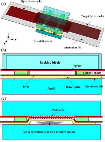
Figure 1. Schematics of the vaporizing foil actuator welding setup. (a) Isometric view of the setup; (b) side view of the setup showing the SS driver plate is on top of the aluminum foil, flyer made of NiTi wire stack and the standoffs between flyer and target; (c) side view of the weld structures after foil vaporization.
Download figure:
Standard image High-resolution imageThe interfacial microstructures of the NiTi/NiTi welds and NiTi/SS welds were examined through optical microscopy and scanning electron microscopy (SEM). The elemental distributions were measured by energy-dispersive x-ray spectroscopy (EDS). The phase transformation characteristics of the NiTi BM, NiTi/NiTi welds, and NiTi/SS welds were measured by differential scanning calorimetry (DSC) using a DSC2500 calorimeter made by TA instruments. DSC tests were conducted at temperatures ranging from −80 °C to 120 °C with a controlled heating/cooling rate of 10 °C min−1 under an Argon atmosphere following the ASTM F2004-17 standard. All samples for DSC tests were prepared with a dimension of 1 mm by 0.5 mm by 1 mm and a weight of 10–12 mg. Microhardness tests were performed with a square-based pyramid diamond indenter operating at a load of 200 g and a dwell time of 15 s. Figure 2 shows the mechanical testing setups for BMs, similar and dissimilar NiTi welds. The gauge length for all the samples is 50 mm, which is a composite of weld region and BM. Hence, the displacement observed is due to deformation of both regions. Displacement was measured with the linear variable differential transformer in the test-frame base. Because of this and the straightening of bonded samples on initial loading, displacements cannot be accurately related to strains. Lap shear tests were conducted on an MTS EM Test Frame with a displacement rate of 2 mm min−1 for NiTi BM, SS BM, NiTi/NiTi welds and NiTi/SS welds. Three replicates for each type of the samples. The cycling tests were performed with displacement control (0 to 2 mm to 0) under a crosshead displacement rate of 0.04 mm min−1 mm−1 based on ASTM F2516-18 standard. The gauge length of the tested specimens is 50 mm so that the displacement rate is 2 mm min−1 and the cycling strain is 4% for all samples. A limited number of 100 cycles were performed on all the samples.

Figure 2. Mechanical testing schematics. (a) Mechanical testing setup for NiTi/NiTi, SS/SS, and NiTi/SS welds; (b) Mechanical testing setup for NiTi and SS base metals.
Download figure:
Standard image High-resolution image3. Results and discussion
3.1. Microstructure characterization
The weld interfaces of a typical NiTi/NiTi weld and a NiTi/SS weld were studied in figures 3 and 4, respectively. Wavy interface is characteristic of high velocity impact welding, which was observed in both types of welds. As shown in figure 3(a), shear bands are symmetrically distributed along the interface of NiTi/NiTi welds and indicate a thermomechanical instability [35]. During VFAW process, high strain rate plastic deformation would induce local temperature rise on the interface, resulting in strength loss. Meanwhile, strain or strain rate hardening will strengthen the interface. If the strength loss due to thermal softening is larger than the increase in strength due to strain rate hardening, plastic instability can induce localized band-like deformation, such as shear bands or further shear cracks [36–39]. Some black dots shown near the interface are the remnants of etchants, while oxides or carbides are exhibited at the far side of the interface. This is the initial work being conducted without parameter optimization. In ideal conditions, these shear bands could be eliminated, and a clean solid-state wavy interface will form.
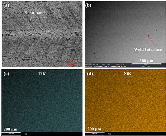
Figure 3. NiTi/NiTi weld interface characterization. (a) Optical image showing wavy nature with shear bands; (b) SEM-BSE image of the weld interface; (c) EDS map of Ti distribution; (d) EDS map of Ni distribution.
Download figure:
Standard image High-resolution image
Figure 4. NiTi/SS weld interface and associated with EDS map analyses.
Download figure:
Standard image High-resolution imageNo elemental segregation as may take place during solidification or selective volatilization was observed in either the similar or dissimilar welds. BSE-SEM image in figure 3(b) of the NiTi/NiTi weld can barely show contrast at the weld interface, which was confirmed by the EDS maps of Ti and Ni. The EDS maps exhibited homogeneous distributions of Ni and Ti through the whole examined area. This homogeneous elemental distribution was also observed in the NiTi/SS weld interface, as shown in figure 4. The elemental distributions of Ni, Ti, Fe, and Cr, the major elements of NiTi and SS, show a sharp transition across the NiTi/SS interface. Solid-state and homogeneous weld interfaces indicate strong bonding, resulting in superior mechanical and functional property tests which will be studied in the following sections.
3.2. Phase transformation characteristics
Phase transformation temperatures have been good indicators for the functional properties of nitinol welds. After impact welding, these temperatures can be expected to change due to the severe plastic deformation involved in the welding process. Phase transformation temperatures such as  ,
,  ,
, ,
,  ,
,  and
and  were determined through the intersection of the baseline with the line of maximum inclination of the transformation peaks based on the ASTM F2004-17 standard. However, due to the small joining area in VFAW welds, DSC samples for NiTi/NiTi and NiTi/SS welds retained certain amounts of NiTi and SS BM. This will influence the DSC results due to the overlapping effect. Based on the results in figure 5, however, the overlapping effect is insignificant due to the much lower heat flow peaks in the NiTi/NiTi and NiTi/SS welds.
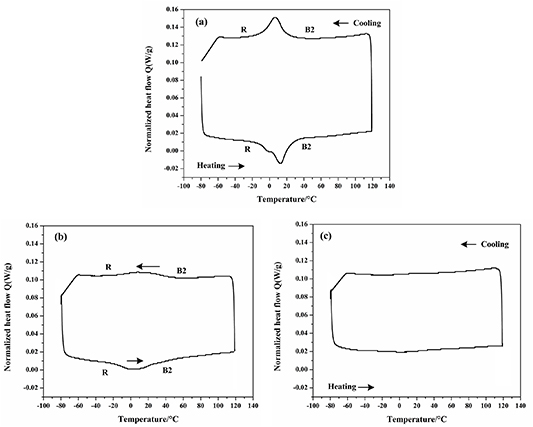
Figure 5. Comparison of differential scanning calorimetry (DSC) testing results on NiTi base metal (BM) in (a), NiTi/NiTi weld in (b), and NiTi/SS weld in (c).
Download figure:
Standard image High-resolution imageEnthalpies and hysteresis values from DSC curves signify the extent of phase transformation. As reported by [40, 41], a complete reversible B2–B19' transformation normally exhibits enthalpies ranging from 10 to 25 J g−1 and hysteresis values ranging from 35 to 50 °C. As shown in table 1, the calculated enthalpies and thermal hysteresis values for NiTi BM and NiTi/NiTi welds are lower than 5 J g−1 and 15 °C, respectively. This means that there is only an intermediate reversible B2-R phase transformation in the NiTi BM and NiTi/NiTi welds, as shown in figure 5. This intermediate phase transformation is likely due to the presence of precipitates and nanocrystalline grains in the NiTi, or large plastic deformation induced by the VFAW process. These all assist in constricting the structure and thus restricting the complete B2–B19' transformation [42].
Table 1. Transformation temperatures (°C), thermal hysteresis ( ), and enthalpies (
 ) of the NiTi base metal, the NiTi/NiTi weld, and the NiTi/SS weld where
  and
and  indicate the austenite start and finish temperatures, respectively;
  and
and  indicate the R phase start and finish temperatures, respectively;
  and
and  indicate the martensite start and finish temperatures, respectively.
| Transformation temperatures (°C) |
 (J g−1) (J g−1) | ||||||||
|---|---|---|---|---|---|---|---|---|---|
| Samples |

|

|

|

|

|

|
 (°C) (°C) | Cooling | Heating |
| NiTi BM | −15.3 | 26.4 | 22 | −12 | — | — | 7.27 | 2.98 | 3.13 |
| NiTi/NiTi weld | −34.6 | 54.5 | 55 | −19.6 | — | — | 12.45 | 1.23 | 3.94 |
| NiTi/SS weld | — | — | — | — | — | — | — | — | — |
It was observed in figure 5 that the heat flow peaks are much lower in the NiTi/NiTi and NiTi/SS welds compared to that in the NiTi BM. This indicates that the martensitic transformation has been significantly suppressed in the welds made by VFAW process. Table 1 shows that the NiTi/NiTi weld exhibited a widened transformational temperature range compared to the NiTi BM. Plastic deformation is known to broaden the transformation temperature range and reduce the magnitude of the transformation peaks due to the increased barrier to transformation [27, 43]. The plastic deformation can also make transformation impossible due to the restriction of the microstructure [44]. No heat flow peaks were observed in the NiTi/SS welds. The inactive SS side of the weld may further impeded transformation compared to the NiTi/NiTi weld. The thermal mass of the SS side of the weld may also affect the DSC measurements; there may have been limited transformation in the NiTi but it was below the detection limits of the system.
3.3. Mechanical properties
3.3.1. Microhardness measurement.
The severe plastic deformation involved in the VFAW process could induce grain refinement near the weld interface [45], which increases the hardness in the adjoining regions [46]. Figure 6 shows the hardness distributions across the interfaces of NiTi/NiTi and NiTi/SS welds. Note that the hardness measurements on the NiTi side might not as quantitatively accurate as those on the SS side due to the possible partial recovery of the indentations induced by the stress induced martensite transformation. However, the general trend of hardness distributions is useful to examine the mechanical behavior of nitinol BM and welds.
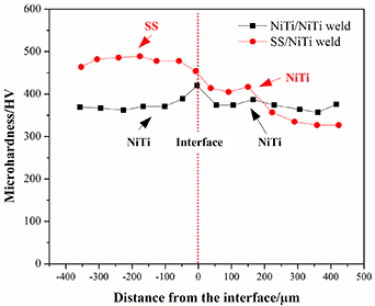
Figure 6. Microhardness distributions across the NiTi/NiTi and NiTi/SS interfaces.
Download figure:
Standard image High-resolution imageFor NiTi/NiTi welds, the interface gained 8% hardening compared to the NiTi BM. For NiTi/SS welds, the NiTi side exhibits the same hardening effect, and the interface near the SS side shows comparable hardness to the SS BM. These hardness distributions show that no HAZs were formed in the VFAW nitinol welds. This phenomenon has also been observed in explosive welding of nitinol to steel [28] and VFAW of other metal combinations such as Al/Fe [32] and Ti/SS [33]. This lack of HAZ formation and the strengthened weld interfaces are contrary to other traditional fusion-based and solid-state welding technologies which normally involve structural coarsening and softening.
3.3.2. Lap shear tests.
Lap shear tests were conducted to measure the macro mechanical properties of similar and dissimilar nitinol welds. Figure 7(a) compares the lap shear testing results among NiTi BM, SS BM, SS–SS weld, NiTi/NiTi weld and NiTi/SS weld. Note that the nominal stress is calculated through dividing the load by the cross-section area of the BM wires, and the nominal strain is the ratio of crosshead displacement to the gauge length. It was seen that NiTi/NiTi weld possesses very similar stress–strain curve as the NiTi BM, that is, similar elastic response, similar stress induced martensite (SIM) plateau (around 400 MPa), and similar elastic/plastic deformation of martensite to failure. NiTi/SS weld exhibited a stress–strain curve somewhere between those of NiTi/NiTi weld and SS–SS weld. The stress plateau of NiTi/SS weld is narrower and more inclined compared to that in NiTi/NiTi weld due to half of the gauge length being SS, which plastically deformed. In this work, the elongation rates for NiTi BM and nitinol welds are not directly related and cannot be compared due to the lap-type joint configurations for NiTi/NiTi and NiTi/SS welds. The peak load for NiTi BM is used as a reference to calculate the joint efficiencies for NiTi/NiTi and NiTi/SS welds. The difference of the slope of the elastic stage for stress–strain curves shown in figure 7(a) is caused by the difference in the sample format. For the NiTi–NiTi weld, due to its lap joint type, rotation of the weld during lap shear testing likely causes the difference of displacement and thus different calculated elastic slope. It was observed that the elastic slope of the stress–strain curve of SS BM is much larger than that of the NiTi BM due to the much larger elastic modulus in SS. The real elastic modulus of the material would not be changed by the VFAW process.

Figure 7. (a) Comparison of typical load-displacement relationships of the NiTi base metal (BM), SS base metal, SS–SS weld, NiTi–NiTi weld and SS–NiTi weld; (b) Typical images for NiTi/NiTi welds before and after lap shear tests showing the fracture locations; (c) Comparison of joint efficiency of NiTi/NiTi welds made by TIG welding [11, 47], laser welding (LSW) [1, 5, 15, 18, 48–51], and VFAW in the current work; (d) Comparison of joint efficiency of NiTi/SS welds made by laser brazing (LB) [21], LSW [1, 4, 15, 52–54], and VFAW in the current work.
Download figure:
Standard image High-resolution imageThe joint efficiencies of NiTi/NiTi and NiTi/SS welds made by different welding methods were compared in figures 7(c) and (d). For similar welding of NiTi to itself, the joint efficiencies of TIG welds are around 38%–60% [11, 47]. NiTi/NiTi laser welds entail relatively higher efficiencies ranging from 40%–86% [1, 5, 15, 18, 48–51], while both TIG and laser welds present lower joint efficiencies compared to NiTi/NiTi welds made by VFAW (103.1%). For dissimilar welding of NiTi to SS, the joint efficiencies for welds made by other traditional methods such as laser brazing [21] and laser welding [1, 4, 15, 52–54] range from 15% to 60%, which are much lower than those in VFAW (96.3%). Both NiTi/NiTi and NiTi/SS welds fractured at the NiTi BM after lap shear testing which further confirms that the welds are stronger than the BM, as shown in figure 7(b). This shows the superior mechanical properties that VFAW can achieve in dissimilar welding of NiTi to SS compared to other traditional welding technologies. This is due to the solid-state welding interface, the lack of HAZ formation and the interfacial hardening as studied in sections 3.1 and 3.3.1.
3.3.3. Cycling tests.
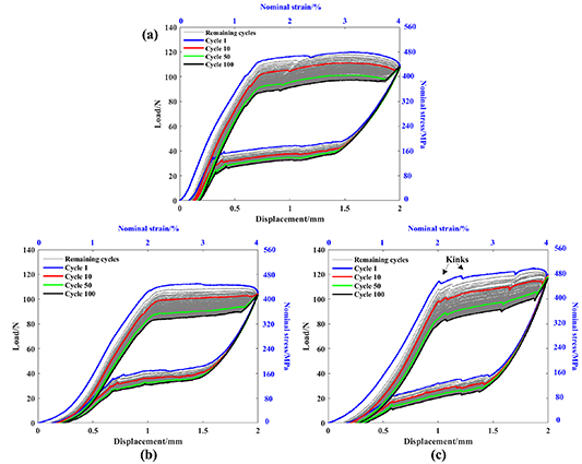
To determine the superelastic behavior and its repeatability of the similar and dissimilar nitinol welds, 100 stress–strain cycles were conducted on the NiTi BM, NiTi/NiTi welds, and NiTi/SS welds. The results in figure 8 show that both NiTi/NiTi and NiTi/SS welds present very similar PE curves as the NiTi BMs. Specifically, they exhibited similar SIM plateaus, and the SIM load plateau value decreases and then stabilizes as the cycle number increases [9]. This might be due to the dislocation build-up and the stored strain enabling easier transformation in the successive cycles [55, 56]. The irrecoverable strains for NiTi/NiTi and NiTi/SS welds are less than 0.5% and 0.68%, respectively, which are comparable to that in the NiTi BM (0.37%). It is worth mentioning that NiTi/SS welds show a slightly slower stabilization due to the plastic deformation of SS. The curves are also twisted due to the asymmetry of transformation (only one half of the assembly is transforming). After 100 cycles, these welds did not fracture. When these cycling tested welds are strained to fracture, they still retained around 80%–85% of the UTS of the NiTi BM (Not shown in figure 8). See supplementary data.
Figure 8. Comparison of cycling tests results among NiTi base metal (a), NiTi/NiTi weld (b) and NiTi/SS weld (c) after 100 cycles. The 1st, 10st, 50st, and 100st cycle were highlighted in different colors.
Download figure:
Standard image High-resolution image
Fusion-based welding normally involves the consumption of NiTi BM in this fusion zone, resulting in variation and even elimination of superelastic properties [12, 57, 58]. In laser welding of NiTi SMA [59], the welds present a lower onset martensitic transformation stress, slower stabilization of the superelastic response and higher irrecoverable strain than the NiTi BM. This was also found in TIG welding of nitinol [41]. This reduced functional property is due to the thermally induced defects such as grain growth, recrystallization and formation of brittle intermetallics in the weld zone. It can be concluded that good retention of the superelastic property and strength in the VFAW nitinol welds could be ascribed to the lack of HAZ formation, the solid-state bonding interfaces and the grain refinement near the interfaces.
4. Conclusions
Similar and dissimilar solid-state microwelding of NiTi and SS wires through a high strength impact welding process have been conducted and significant findings are as follows:
- (a)VFAW can join thin nitinol wire to itself and to SS wire in solid-state. This impact joining can be optimized and presumably adapted to other geometries and drive mechanism, such as laser-driven impact welding.
- (b)Typical solid-state wavy interfaces were observed in both NiTi/NiTi and NiTi/SS welds. No elemental segregation was observed.
- (c)Phase transformation characteristics were seen to change after welding. DSC results show that both NiTi/NiTi welds and NiTi/SS welds pertained widened phase transformation temperature ranges than those in the NiTi BM, which is due to the severe plastic deformation involved in VFAW process.
- (d)Microhardness tests show that no HAZs were observed in either type of welds based on the interface hardening occurred at the weld interfaces. Lap shear tests show that NiTi/NiTi welds made by VFAW entail a joint efficiency of 103.1% which is much larger compared to less than 86% in the best of other welding methods. NiTi/SS welds present much higher joint efficiency (93.6%) compared to less than 60% for other traditional joining technologies. VFAW proves it as a reliable solid-state microwelding method for similar and especially dissimilar welding of nitinol wires.
- (e)Cycling tests show that VFAW can retain near 100% of the functional properties of NiTi BM without post-weld heat treatment. Both types of welds show very similar superelastic properties such as stabilizing and limited plastic deformation (irrecoverable strain) as the NiTi BM. Good retention of functional properties in these VFAW welds can be ascribed to its solid-state bonding interface and grain refinement near the interface.
Acknowledgments
We would like to acknowledge the assistance of Wayne Papageorge and John Gosser at The Ohio State University for doing DSC tests and mechanical tests on the NiTi base metal and nitinol welds, respectively.