

Abstract
A tunable symmetric bistable micro-machined mechanism with monolithic structure is presented. The mechanism consists of two sets of pre-shaped beams of similar properties and dimensions; however with one set is curved opposite to the other. The bistability is induced by creating a negative stiffness behavior at the initial position of the moving part to break its stability. This is possible at a certain electrothermal axial loading of both beam sets. The active bistability is symmetric with respect to the initial position. The distance between stable positions is tunable with the applied electrothermal voltages. The mechanism can be used as a tunable bi-directional actuator with different applied voltages. The design and concept are demonstrated based on finite-element simulations and experimental measurements.
Export citation and abstract BibTeX RIS

Original content from this work may be used under the terms of the Creative Commons Attribution 4.0 license. Any further distribution of this work must maintain attribution to the author(s) and the title of the work, journal citation and DOI.
1. Introduction
Buckled and pre-shaped beams are widely used as bistable mechanisms at the small and large scale [1]. These mechanisms are employed in various applications in many sectors, including soft robotics [2], metamaterials [3], multistable positioning [4, 5], resonators [6, 7], actuators [8], gas sensing [9], pressure sensing [10], threshold sensing [11, 12], logics [13], space applications [14], biomedical [15], and energy harvesting [16, 17].
These mechanisms are attractive due to their many advantages, such as simplicity, small footprint, monolithic and compliant structures, passive holding, low actuation energy, large deformations at small forces and within elastic limits, energy storage, eliminating friction and backlash, and negative stiffness behavior.
The buckled beam configuration is mainly obtained by axial compression. The snap-through behavior of post-buckled beams is symmetric between the two sides of buckling. This results in non-conditional bistability. In contrast, pre-shaped beams are easier to be implemented in monolithic structures, where there is no need for axial compression. However, due to their shifted initial state, the initial stable side has more margin of stability, while the second stable position exists under some conditions [18–20].
Buckled and pre-shaped beams are known for having a negative stiffness behavior in their snap-through zone of deflection. This is necessary condition for bistability. A negative stiffness behavior means that the restoring force of the moving part decreases with further displacement. Electrothermal axial actuation of a beam can result in enlarging the negative stiffness zone of deflection.
In this paper, we present a tunable symmetric bistable mechanism with a monolithic structure. The concept is based on breaking the stability of the moving part at the as-fabricated position to create bistability.
The mechanism consists of two sets of pre-shaped beams, curved opposite to each other, with the same properties and dimensions. The opposite beams are connected to a shuttle at their mid-length. In the passive state (without axial load), this creates a high rigidity relatively characterizing the lateral displacement of the shuttle.
Axial and lateral forces between the two inverted beams sets are induced via electrothermal Joule's heating of the beams using the same voltage load. Due to the similarity between the opposite beams, the shuttle initial position (zero displacement) remains at a zero force position after applying the same voltage load on both sides. The initial position becomes unstable at a certain level of heating, since the shuttle lateral stiffness becomes negative. This leads to bistability.
The design of the bistable mechanism ensures a symmetrical snap-through behavior; the snapping force variation with the shuttle displacement is equivalent in both lateral directions. Hence, in the bistability conditions, the distance from the initial to the two stable positions is equal and is tunable with the electrical inputs. Further, the mechanism can be used as a bidirectional actuator by differentiating the electrical inputs on the opposite beams.
The rest of the paper is organized as follows. The snap-through behavior of pre-shaped beams is described in Section 2. The creation of a negative stiffness behavior at the initial position by electro-heating the pre-shaped beams is described in Section 3. The concept of the tunable bistable mechanism is presented in Section 4. Experiments on micro-fabricated prototypes of the tunable bistable mechanism are presented in Section 5. Advantages, limitations, and potential applications of the proposed mechanism are discussed in section 6.
2. SNAP-through of pre-shaped beams
The parallel configuration of pre-shaped beams contains several beams with similar shape and dimensions connected to a shuttle at their mid-length as shown in figure 1. Compared to a single beam, the parallel configuration prevents the activation of the anti-symmetrical modes of buckling. This enhances the bistability of the pre-shaped beams and constraints a linear snap-through displacement of the shuttle [20]. The most common shapes of pre-shaped bistable beams mechanisms are the curved and inclined shapes [20].
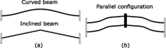
Figure 1. Single (a) and parallel (b) configurations of preshaped beams.
Download figure:
Standard image High-resolution imagePre-shaped beams are used in microelectromechanical systems (MEMS) due to their ease of fabrication without the need of external forces or hinged boundaries to induce buckling. However, their snap-through behavior is not ideally symmetric between the two sides of buckling. A symmetrical snap-through behavior results in a non-conditional bistability and similar margin of stability between the two sides of buckling. Pre-shaped beams with variable cross-section were designed to enhance the symmetry in the snap-through behavior [21–24]. The symmetry indicates that the switching force is similar in the forward and backward directions. This is practical for applications where the same conditions are required from the two stable sides. Besides, the symmetry allows designing a robust bistable mechanism, even with very small distance between stable positions.
Figure 2 shows the typical snapping force curve for a pre-shaped bistable curved beam. The snapping force  is the actuating lateral point force applied to the shuttle; its magnitude is equivalent to the static restoring force of the beams at the midpoint with an opposite direction. The force and displacement direction and the dimensional parameters are clarified in figure 3. The existence of positive and negative snapping force indicates bistability; the beam is pushing towards the other side of buckling after certain level of deflection. The bistability for pre-shaped beams exists after some level of the initial height to thickness ratio
  [20].
[20].

Figure 2. Snapping force curve of a bistable preshaped beam.
Download figure:
Standard image High-resolution image
Figure 3. Schematic of a preshaped curved beam.
Download figure:
Standard image High-resolution imageA stable position has two essential properties: zero snapping force (  ) indicating the absence of restoring force at this position, and a positive stiffness behavior (
 ). In the distance between the two stable positions of a bistable structure, the beams are more axially compressed
  . This results in a negative stiffness behavior (
 ) after some limits of axial compression [20]. The intermediate negative stiffness zone is necessary for the existence of two stable positions. Considering parallel configuration, in which two beams are connected by a shuttle in the middle, the axial compression is capped by the third critical load
  [20]. At this limit, the third mode of buckling appears in the beam shape, resulting in a linear negative stiffness behavior (
 c
c , c is a constant) as shown in figure 2.
In this work, we are interested in extending the range of negative stiffness behavior to reach the initial position  . This is possible with electrothermal heating as clarified in the next section.
3. SNAP-through of electro-thermal actuators
Parallel pre-shaped beams are used also as electro-thermal actuators. The bistable beam dimensions are chosen usually to enhance the bistability [25] (distance between stable positions, holding forces, miniaturization, etc), while the beam actuator dimensions are chosen to maximize the actuator output (free and loaded displacement) [26]. Figure 4 shows schematics of a curved beam actuator in different states: in the initial state (figure 4(a)), with electrical activation and free load (figure 4(b)), with a point load (figure 4(c)), and with the third mode of buckling considering parallel configuration and excessive point load (figure 4(d)).

Figure 4. Configurations of an electrothermal curved actuaor at rest (a), after eletctrothermal heating (b), with a pushing point load (c), and with the third mode of buckling due to an excessive load (d).
Download figure:
Standard image High-resolution imageThe electrothermal heating results in an expansion of the beam length, due to the induced axial compression load. The structure of the beam amplifies the length expansion (which is usually small) to a larger lateral displacement  . At free load, the thermal expansion moves up the beam mid-point (
 ) and extends the snapping zone of the beam. Figure 5 shows the snapping force curve of a pre-shaped curved beam with and without electrothermal heating.
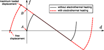
Figure 5. Snapping force of a pre-shaped curved beam with and without electrothermal heating. Points A and B are at the initial position of both snapping force curves.
Download figure:
Standard image High-resolution imageThe third mode of buckling is still activated with electrothermal heating at the critical load. The resulting negative stiffness with the third mode of buckling keeps the same value (negative force curve slope) as shown in figure 5. The negative stiffness behavior helps snapping to the other stable position, and hence enhances bistability. However, buckling at the third mode is not desirable for electrothermal actuators since the negative stiffness limits their capacity to push higher loads.
The snapping zone (including negative stiffness zone) extends continuously with the applied voltages. After some voltage limit, the stiffness at initial position  becomes negative as the case presented in figure 5 (point
  ). The bistable mechanism presented in this paper is based on the creation of a negative stiffness behavior at the initial position to break its stability and create a tunable bistability.
4. A tunable symmetric bistable mechanism
The tunable symmetric bistable mechanism presented in this paper consists of two opposite sets of preshaped beams with similar material and dimensions. The two opposite sides are connected to the same shuttle at their mid-length as shown in figure 6.

Figure 6. Tunable symmetric bistable device.
Download figure:
Standard image High-resolution imageLet  ,
,  ,
,  ,
,  ,
,  , and
, and  be the lateral deflection and snapping force of sets 1 and 2 and their combinations, respectively. The deflection parameters (
 ,
,  ,
,  ) are positive when the shuttle moves in the same arrows direction (i.e. downwards for
  and
and  and upwards for
  ), and are negative in the other direction. Similarly, the force parameters (
  ,
,  ,
,  ) are positive when the snapping force is applied to the shuttle in the same arrows direction, and are negative in the other direction. The connection of inverted beams to the same shuttle imposes the following displacement constraint:

The snapping forces vary with the applied voltages and deflection. The snapping forces  and
and  are related to the total snapping force
  as follows:

Considering the same applied voltages  , the similarity between the two opposite sets of pre-shaped beams imposes the following constraint in terms of snapping forces:

Substituting (3) into (2), we notice the symmetry of the total snapping force with respect to the initial position:

The symmetric property in (4) indicates the zero snapping force at the initial position:

Hence, for the same voltage difference applied on both sides, the initial position is a stable position as long as the lateral stiffness around it is positive  . At low voltages, both set of beams show positive stiffness behavior at the initial position as explained in the previous section. After some voltage, each set of beams shows negative stiffness behavior at the initial position, which results in a total negative stiffness
  . Inducing the negative stiffness in this way breaks the stability of the initial position and leads to bistability. Figure 7 shows the total snapping force curve in the case where each set of the opposed pre-shaped beams has the same snapping force curve of the example presented in figure 5 with electrothermal heating.
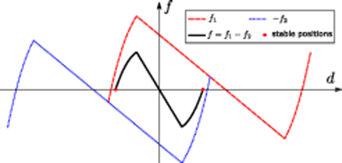
Figure 7. Total snapping force for the tunable symmetric bistable device.
Download figure:
Standard image High-resolution imageIn case of bistability, the total snapping force symmetry with respect to the initial position (4) provides the same margin of stability between the two stable sides. This is a main advantage with respect to the shifted and conditional bistability of preshaped beams. The case shown in figure 7 is for one voltage  that is higher than the critical voltage of bistability. Figure 8 shows the variation of the total snapping force curve for different applied voltages.
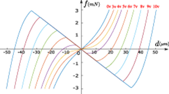
Figure 8. Simulated curves of snapping force versus deflection for the tunable symmetric bistable device with various electrothermal voltage loads  .
.
Download figure:
Standard image High-resolution imageThe curves in figure 8 are calculated with finite element (FE) simulations for a device similar to figure 6 with the following dimensions for each beam:  = 2 mm,
  = 9.2 μm,
  = 13.2 μm, and
  = 25 μm. The material properties for a doped silicon are considered (resistivity
  : 0.124
  mm, Young's modulus E: 169 GPa, density
  : 2.32 g cm−3, thermal conductivity
  : 149 W m−1 K−1, specific heat
  : 706 J Kg−1 K−1, and temperature dependent thermal expansion coefficient
  [27]). These parameters result in good agreement with the experimental measurements as shown in the next section.
Finite element simulations have been used to obtain the snapping force curves in figure 8. The element type 'plane223' is used in the FE software Ansys with structural-thermoelectric static analysis. Up to V = 4 v, the simulations are simply made by firstly increasing the voltage with small steps while fixing the shuttle, then, at the voltage level, the shuttle is moved with small steps and the snapping forces are obtained. For higher voltages, where the negative stiffness and third mode of buckling start to occur, the first scenario makes divergence. The scenario in this case is to move the shuttle to one side at zero voltage, increases the voltages and then moves back the shuttle with small steps. Constraining the symmetry with respect to the beams mid-length reduces the problems of divergence in the simulations.
At zero voltage, the mechanism is stiff against lateral displacement of the shuttle. The stiffness revealed by the lateral stiffness (slope of snapping force curve) at the initial position starts to decrease after applying voltages as shown in figure 8. After a critical voltage limit, the lateral stiffness becomes negative and two stable positions are induced. At higher voltage, the distance between stable positions increases as the snapping zone is expanding. Figure 9 shows variation of the stable positions of the mechanism at different voltages.
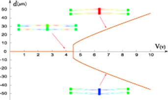
Figure 9. Stable positions for the tunable symmetric bistable device with various voltages  .
.
Download figure:
Standard image High-resolution imageThe snapping force around the critical voltage is highly sensitive to voltage and displacement variation, as shown in figure 9. This high sensitivity is suitable for sensing applications, where materials with biological, chemical or physical dependent properties can be used. Further, the restoring forces in this zone of voltage (around the critical voltage) is limited to a certain extent, which allows a near zero-force displacement behavior.
Furthermore, the bistable mechanism can be used as a bidirectional actuator by differentiating the voltages applied on the two beam sets. A close configuration for a bidirectional actuator is reported in [28], where Z-shaped beams are used due to their similar lateral stiffness in the two directions of motion. The working principle is to activate one side to make a motion or to push loads, while keeping the other side inactivated. The actuator in this case has low stiffness and limited force capabilities due to the opposite internal forces between both sides. The electrothermal heating reduces the lateral stiffness of one beam actuator at its initial position as explained previously. Hence, activating both sides of the mechanism with different voltages results in an improved actuating performance in the two directions of motion.
These applications are not investigated in this paper. Neverthelss, the bidirectional actuation is used in the experiment, as shown in the next section, to choose the stable side after applying voltages. Activating the beams in one side slightly before those in the other side favors switching the shuttle to one stable side rather than the other.
5. Experimental measurements
The theoretical concept of the tunable symmetric bistable mechanism is tested experimentally on microfabricated prototypes. The prototypes are fabricated on SOI wafers (25 μm device layer) using SOI-MUMPsTM fabrication process through MEMSCAP [29]. The beam dimensions measured after fabrication are the same considered for the FE simulations in figures 8 and 9, except for the length, which is 1 mm. In the previous section, we choose to present the simulation for larger length to show that this reduces the critical voltage of bistability due to the increase in the beam length expansion (i.e. more axial load at the same voltages). Further, changing the length does not change the maximum temperature reached at the same voltages (to a large extent), as shown later in this section. This indicates that the range of bistability for the mechanism with acceptable temperature limits can be increased by increasing the length.
The prototypes are tested on-wafer using Cascade Microtech's Summit 12 000 AP semi-automatic probe station, as shown in figure 10.
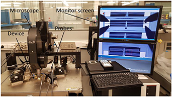
Figure 10. Experimental setup.
Download figure:
Standard image High-resolution imageThe voltages are applied through probes using a programmable power supply (keysight E36234A) allowing coupled outputs with delays. The voltages are applied on the pads as clarified in figure 6 with a delay between  and
and  . For low voltages below the critical voltage of bistability, the triggering order between
  and
and  is not important since the beam will come back to the initial position after activating both voltages. In case of bistability at higher voltages, activating
  slightly before
  switches the shuttle to the top stable side, while inversing the sequence order switches the shuttle to the bottom stable side. Figure 11 shows the switching sequence in both cases. A small delay of several milliseconds is enough to favor the displacement in one direction. We considered a delay of 0.5 s in the experiments.

Figure 11. Voltage sequence to switch up or switch down.
Download figure:
Standard image High-resolution imageThe mechanism shuttle displacement is measured using the camera software. Figure 12 shows the bistable mechanism before and after applying voltages on the pads with a zoom on the shuttle at initial, top, and bottom positions.

Figure 12. The bistable device at (a) zero voltage, (b) the upper, and (c) bottom stable positions at high voltages.
Download figure:
Standard image High-resolution imageThe experimental tests were carried out on several prototypes with the same dimensions. Very close behavior is shown between the different prototypes. Table 1 shows the displacement measuremenets of the bistable mechanism for different applied voltages. The measurements validate the concept of the bistable mechanism. At voltages below 4 v, the displacement is very small, even when activating only one side. For voltages up to 8 v, the shuttle comes back to the initial position after activating both sides. The critical voltage of bistability is between 8 v and 8.5 v ( ). At
). At  = 8.5 v, a huge snap of the shuttle to top or bottom positions is noticed relatively to a small voltage variation. Afterwards, the distance to stable positions increases for higher voltages.
Table 1. Experimental displacement measusrements on the fabricated prototype in response to electrical inputs.
| Voltage (v) | ||
|---|---|---|
 |
 |
Displacement (μm) |
| 4.1 | 4 | 0 |
| 5.2 | 5 | |
| 6.4 | 6 | |
| 7.7 | 7 | |
| 8 | 7.5 | |
| 8.6 | 8 | |
| 9 | 8.5 | +9.5 |
| −10.4 | ||
| 9.3 | 8.75 | +11.7 |
| −11.9 | ||
| 9.5 | 9 | +12.4 |
| −12.7 | ||
The concept of the tunable symmetric bistable mechanism is based on applying the same voltage difference on both opposite pre-shaped beam sets. The small difference in voltages experimentally is set to calibrate both sides to have the same force-displacement behavior, as much as possible. This difference could be attributed to the difference in cable and probe contact resistances or some microfabrication imperfections. The experimental measurements show good agreement with FE simulations as shown in figure 13.
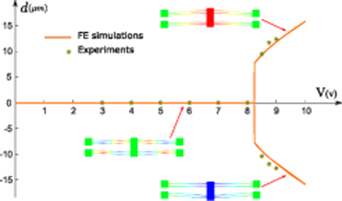
Figure 13. Comparison of stable positions between FE simulations and experiments.
Download figure:
Standard image High-resolution imageAs shown in figure 13 and noticed experimentally, the mechanism displacement at the critical voltage of bistability (near 8.4 V) is very sensitive to the applied voltages. Slightly before the critical voltage, we notice a weak equilibrium of the mechanism at the initial position, where the shuttle is sensitive to external disturbances like vibration. Above the critical voltage, the distance between stable positions increases with more voltages. However, in the fabricated prototypes, the range of bistability is very limited where the bistable mechanism shows failure due to the high temperature level after 10 V. Further, we notice that the mechanism changes its properties or shape plastically after working at high temperature for long time. This is revealed by a shifting of the critical voltage of bistability to a higher level.
6. Advantages, limitations, and potential applications
The tunable bistable mechanism shows several advantages, making it promising for different applications. It has a simple and monolithic structure. This simplifies the design, fabrication, and integration of the mechanism with other MEMS structures for more complicated functions. The tunable bistable mechanism has a symmetrical snap-through behavior and bistability, while not requiring spceical mechanisms to induce buckling, such as external axial forces, moveable boundaries, or initial activation [30].
The symmetry makes the proposed mechanism beneficial for bistable mechanism applications, since there is no need to deal with different holding/switching conditions at each stable position.
The holding and switching at and between stable positions are essential functions for the functioning of bistable and multistable devices. The holding in the proposed mechanism relies on the elastic stability of the structure, at different levels of electro-thermal heating, between the two lateral sides. The switching of bistable mechanisms is usually carried using additional actuators pushing the moving part to switch between stable positions. In the proposed mechanism, the switching can be made using the mechanism itself with no need for external actuators. Switching is achieved by electro-thermally activating/de-activating the beams, in each of the opposite sides, one before the other.
The tunability is an additinoal advantage of the proposed mechanism compared to other bistable mechanims. It can be used for applications where the stable position needs to be tuned or set at very small or very large distance with respect to dimensions. The holding/snapping forces can be tuned as well between the two sides of stability. This is helpful for applications where the snap-through is used as indicator for reaching a threshold limit of a physical quantity, such as acceleration or flow. The tunability in this case helps to increase the range of sensing and its accuray.
Further, the displacement at the critical voltage of bistability is very sensitive for small variations in the electrical input. Using a beam material sensitive for a physical stimulus, such as humidity, temperature, gas concentration, the shift in the critical voltage can be used for sensing applications.
Furthermore, the snapping forces around the critical voltage of bistability are very small (see figure 8). This helps to extend the range of displacement with small restoring forces. Due to symmetry, the proposed mechanism has a zero force and negative stiffness behavior at the initial position, in the bistability conditions. Thus, adding this mechanism to an equivalent positive stiffness mechanism (such as a cantilever beam, a spring, etc) cancels out the opposite restoring forces and makes a near zero-force displacement mechanism.
The tunable bistable mechanism can be used also as a bidirectional actuator by differentiating the electrical inputs on the two opposite beam sets. Each of the opposite beam sets acts as a beam electrothermal actuator (like a V-shape). Applying voltages to one beam set in one side separately moves the middle shuttle towards that side and deflects the beams in the other side in their range of snap-through.
The opposite configuration of the proposed mechanism has an advantage of compensating the effects of residual stresses after fabrication. The residual stresses will make an expansion of each beam, which is similar to the effect of electrothermal heating. The residual stress would be the same in the different beams, as they have the same material and dimensions. This results in zero displacement at the middle shuttle due to the opposite configuration. This is helpful as well to reduce the critical voltage limit for the proposed mechanism.
In terms of performance, the force and distance between stable positions of the tunable bistable mechanism increase with the applied voltages. The maximum voltage that can be applied, without failure or plastic deformartion, is limited by two main contraints: temperature and stress limits.
The maximum variation of temperature  (with respect to initial temperature) in a slender pre-shaped beam due to the application of a voltage difference
  between its anchors can be approximated with the following expression:
The expression of  in (6) is calculated based on the electro-thermal heat equation with constant thermal properties and neglected convection and radiation. It shows that the temperature reached in the beam for a certain voltage is independent from the beam dimensions. Figure 14 shows a comparison between FE simulations and the analytical expression in (6) for the maximum temperature reached at different voltages. The same material properties and dimensions (with two different lengths) as the previous simulations are considered in figure 14.
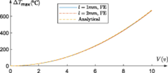
Figure 14. The maximum temperature reached in the beams at different voltages between FE simulations and analytical calculations.
Download figure:
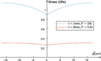
Standard image High-resolution imageThe axial and bending stresses increases in the pre-shaped beams of the bistable mechanism with higher voltages and with lateral deflection. Figure 15 shows variation of the maximum internal stresses in the proposed mechanism obtained with FE simulations (same material properties and dimensions as previously). For a fair comparison, the voltages in figure 15 are chosen differently (with different beam length) to obtain approximately the same distance between stable positions. Note that the stress in pre-shaped beams increases with higher thickness and smaller length [19].
Figure 15. The maximum stress reached in the beams at different voltages.
Download figure:
Standard image High-resolution image
The temperature and stress limit for the material have to be considered as constraints in the design of the tunable bistable mechanism. Considering these limits with safety factors enhances the design robustness. For silicon, the fracture occurs at 2 GPa stress or higher at room temperature [31, 32]. The fracture limit depends on many parameters, including fabrication conditions, crystallographic orientation, geometry, temperature, etc [33]. Silicon properties vary with the temperature and degradate permanently at high temperatures. Silicon electrothermal actuators remain functioninig properly for temperature up to 650 °C. The strength of silicon and its fracture limit reduce at elevated temperature [34]. A failure stress around 0.8 Gpa at temperature of 800 °C is measured on polysilicon structures in [34].
The tunable bistable mechanism with 2 mm length has a low critical voltage of bistability, and a wider working range at low for the tunable bistable mechanism temperature and smaller stresses. Accordingly, a design issue is to lower the critical voltage and increase the range of tunable force and displacement, while adhering to temperature and stress limits.
The opposite forces applied by the opposite beams in the tunable bistable mechanism increase the level of stress inside the shuttle. The shuttle dimensions need to be large enough to support these stresses. In addition, the shuttle and the distance between beams must be large enough to constraint the rotation of the shuttle and ensure a straight displacement. Otherwise, the tunable bistable mechanism will switch between stable positions with tilted configurations. This is because the second mode of buckling with rotation at the mid-point (constrained by the shuttle) is easier to occur with less deformation energy than in the case of the third mode of buckling [18, 19].
The concept of the proposed mechanism is based on applying equally voltage difference on each of the opposite sides of the mechansim. However, a small difference in voltages is set experimentally between the two sides to calibrate a symmetrical snap-through behavior. A remaining challenge is to compensate the difference in the applied voltages on fabricated prototypes to induce symmetric bistability. In addition, developing analytical models for the mechanism is helpful for a better understanding of its behavior, optimising its performance, and tunning the different properties for various applications.
7. Conclusion
The concept, design, and experiments on a tunable symmetric bistable mechanism with monolithic structure are presented. The bistability of the mechanism is based on creating a negative stiffness in the initial position to break its stability. Electro-thermal heating of pre-shaped beams is used to create the negative stiffness behavior at the initial position of the moving part. The symmetry of the mechanism is a main advantage with respect to the bistability of pre-shaped beams. The symmetry is obtained using similar pre-shaped beams, which are opposite to each other and heated with the same voltages. The distance between the stable positions is tunable with the applied voltages. The concept was demonstrated based on FE simulations and experiments, which are in very good agreement. The new mechanism opens the path for promising applications: tunable bistability, bidirectional actuator with more powerful scheme of voltage control, sensing applications, near zero-force mechanism, resonators, etc. Further, the principle of creating bistability by creating a negative stiffness at the initial position can be generalized to other domains, at other scales, and with different tools.
Acknowledgments
This research is supported by KAUST research fund.