

Abstract
Jellyfish are energy-efficient swimmers due to the muscle-powered flapping of their soft bell that facilitates a unique energy recapture mechanism. In this paper, we present a bio-inspired jellyfish robot named Poly-Saora that mimics the swimming behavior of the jellyfish species Black sea nettle (Chrysaora achlyos). An assembly-based fabrication method is used to create the Poly-Saora that is developed mainly with polymeric materials (95% of the robot by volume). Twisted and coiled polymer (TCP) actuators are successfully implemented in this robot and show great potential for underwater applications. The influence of different parameters such as the amplitude of the input power, the actuation frequency, and the lifecycle of the actuator are investigated underwater. A full characterization of 6-ply TCP muscles is demonstrated. An actuation strain of ∼10% is achieved in water at a frequency of 0.1 Hz and 50 kPa load. When integrated into the jellyfish, the TCP was able to bend a single bell by 17°. Poly-Saora was able to swim a vertical distance of 180 mm in 220 s with four TCP actuators each confined in a separate conduit. The robot mimics the swimming behavior of a real jellyfish by contracting the bell segments through the activation of the actuators, which generates forced water circulation under the bell in a pulsating rhythm, consequently creating a vertical movement of the robot. Overall, Poly-Saora presents a model of an underwater system that is driven by stimuli-responsive polymer materials and has unique advantages over conventional rigid robots due to their lightweight, muscle-like structures, silent actuation and ease of manufacturing. This robot can be used for safe interaction with other underwater species and their natural habitats when fully developed.
Export citation and abstract BibTeX RIS
1. Introduction
Since their inception, several robotic and biomimetic machines have focused on motors and pneumatic or hydraulic pistons to produce mechanical motion. Conventional robots have many motors and complex control systems that work together to maximize efficiency and provide movement. Although this has become a standard in most current robots, these 'hard' actuators can also lead to issues such as safety, overheating, cost, and can become extensively complex. Due to recent rapid technological developments, robots are required to perform important tasks in applications such as medicine, search and rescue, disaster response, and human assistance [1]. Therefore, they should be able to handle unexpected interactions with unstructured environments such as functioning underwater. Developing small underwater biomimetic robots is still difficult due to many factors such as selecting actuators that must be safe and efficient for underwater propulsion, sealing the electronics, compactness, wireless motion control, reducing noise, and high propulsive efficiency even at micro level [2].
Smart materials are the basis of many applications such as sensors and actuators. Most smart actuators have the potential to demonstrate similar physical properties (stiffness, elasticity, strength, and density) as biological tissue. It is important to recognize that almost all biological organisms, and certainly all animals, rely on softness. They exploit their softness to bend, twist, and squeeze in order to change shape, hide, and move.
Previously, smart actuators used in underwater robots include, shape memory alloys (SMA) [3–6], dielectric elastomer actuators [7, 8] and ionic polymer-metal composite (IPMC) actuators [9–14]. A summary table is provided in table 1 that consists of information such as size of the robot, type of actuators used, and the speed. These actuators are primarily used to either create oscillation or jet propulsion induced motion to allow the robot to swim underwater. Oscillatory motion of biomimetic fins imparts greater forward thrust and swifter turning capabilities. This was demonstrated by the successful testing of an acoustically controlled soft robotic fish in the Pacific Ocean by a group of researchers at Massachusetts Institute of Technology [15]. In the past decade, several bio-inspired fish [2, 13, 14] and manta ray (Mobula birostris) [4, 7, 11, 12] have been developed using smart actuators that are propelled by the oscillatory motion of biomimetic fins. Many biomimetic jellyfish have been developed and studied over the years by working on the principle of jet propulsion induced motion as well as rowing motion. Their practical application was successfully demonstrated in the Atlantic Ocean by a group of researchers at the Florida Atlantic University using an untethered, hydraulically actuated, soft-robotic jellyfish that could also navigate through orifices [16]. A pneumatic based actuation, Fludojelly (220 mm in diameter) was recently demonstrated in Joshi et al [17], which was able to carry a 100 g load and swim vertically at a speed of 160 mm s−1. Smart actuators find an important application in the development of soft-robotic jellyfish due to their highly compliant configurations and adaptability in unstructured environments. Najem et al [18] presented the development of robotic jellyfish using IPMC actuators that reached a maximum speed of 1.5 mm s−1. In another study, Villanueva et al [5] developed a jellyfish robot called Robojelly using SMA actuator to achieve a proficiency of 0.19 s−1,which is comparable to its biological counterpart that has a proficiency of 0.25 s−1.
Table 1. Comparison of swimming jellyfish robots.
| Power consumption | ||||||||
|---|---|---|---|---|---|---|---|---|
| References | Size | Actuator | Swimming speed (mm s−1) | Voltage (V) | Current (A) | Power (W) | Actuation frequency (Hz) | |
| Non-conventional actuators | Yeom and Oh [9] | 30 mm dia. | IPMC | 0.057 (max) | 3 | — | — | 1 |
| Villanueva et al [19] | 450 cm3 (324 g) | SMA | 78 | — | 3.5 | 19.2 | 1 | |
| Villanueva et al [5] | 164 mm dia. (200 cm3, 242 g) | SMA | 54.2 | — | 1.5 | ∼120 (peak) | 0.5 | |
| Najem et al [18] | 150 mm × 58 mm dia.,20 g | IPMC | 0.77 (4 bells) | 2 | — | 0.7 | 0.1–10 | |
| 1.5 (8 bells) | 2 | — | 1.14 | |||||
| Godaba et al [8] | 140 mm × 118 mm(500 g) | Dielectric elastomer | 10 | 6000 | — | — | — | |
| Zhou et al [3] | 216 mm × 68 mm dia.,20 g | SMA | 111 | — | 1 | — | 1 | |
| Cheng et al [20] | 150 mm × 90 mm(28 g) | Dielectric elastomer | 10 (Tethered) | 7000 | — | — | 1.9 | |
| 5 (Untethered) | 9000 | — | — | 1.6 | ||||
| Kazemi-Lari et al [21] | 76 mm (40.1 g) | SMA coils | 6 | 18–19 | — | 104–115 | 0.5 | |
| Hamidi et al (Poly-Saora, this study), 2020 | 220 mm (diameter) × 200 mm (height) (440 g) | Nylon 6,6 TCPAg | 5 | 20 | 30 | 600 | 0.25 | |
| Conventional\Other actuators | Ko et al [22] | 17 mm, 0.14 g | Magnetic | — | — | 13 | — | 10 |
| Nawroth et al [23] | 10 mm dia. | Bioengineered tissue | 10 | — | — | — | — | |
| Marut et al [24] | 5.7cm × 7.9 cm (46.5cm3,80 g) | iris mechanisms | 116 | 10 | — | — | — | |
| Frame et al [16] | 210 mm dia. (380 g) | Hydraulic | 30 | — | — | 2.29–5.58 | 0.435–0.8 | |
| Joshi et al [17] | 220 mm dia. (500 g) | Pneumatic | 160 | 12 | — | — | 0.8 | |
Twisted and coiled polymer (TCP) muscles are inexpensive and high strength actuators that can appropriately match the performance of mammalian skeletal muscles [25]. Here, in this work, we hypothesize that extremely twisted and coiled silver-coated 6-ply TCP actuators can result in a good swimming characteristics of a robotic jellyfish, when used in a suitable structures and optimum actuation conditions. Using these actuators in robots helps maintain a relatively small weight and volume compared to those fabricated using conventional motors and pneumatic actuators. Employing lightweight artificial actuators that create more space for on-board sensors and exploration devices, will have a meaningful impact in the field of underwater discovery, pollution detection, and video mapping [10].
In this study, we showed the potential of using TCP actuators in an underwater biomimetic robot. Inspired by a real jellyfish, we exploited the swimming capability of our robot by utilizing a 3D printed polymer structure and polymer actuators (figure 1). Jellyfish are underwater sea creatures with soft bodies and anatomies. They are the earliest animals known to swim via jet propulsion produced by contracting circular muscle fibers in their bell [26]. They have high swimming efficiency, which is an attractive design alternative for many engineering applications that require improved efficiency for underwater applications. The body of the jellyfish consists of a dome-like bell and long hanging tentacles. Our jellyfish robot consists of three major parts, namely, the silicone bell that resembles the jellyfish umbrella, a 3D printed structure that contains 8 channels to place the TCP actuators peripherally around the bell, and the TCP muscles themselves as the actuators. This initial design of the robot is inspired by Tadesse et al [27], which is modified to use TCP actuators/muscles in this work. The robot has a polymeric structure that houses the polymer muscles that induce motion. This fact helps us to develop the structure for underwater application without requiring any sealing procedure due to the compatibility and good actuation behavior of the polymer muscle in water. Unlike many structural alloys and pure metals, which can be strongly affected and corroded due to exposure to moisture, polymers are more resistant to chemical reactions and have long-lasting performance in water. However, sealing the structure can reduce the power consumption of the robot and consequently, increase its efficiency. The sealing will also help the safe operation of the robot in water as currently high current is provided to the actuators. Moreover, the low-profile actuators make the robot compact and lightweight. The total weight of our robot considering all the components is 440 g. One of our research goals was to investigate the actuation behavior of the bell under different geometrical and input conditions. Our challenge was to employ key features to enable this novel biomimetic prototype to swim using advanced materials and actuators. By focusing on the deformation of the bell segment, accumulating vital performance data such as mechanical stress and elastic deformation, pre-stress, loading condition, and improving its operating conditions, Poly-Saora was capable of swimming underwater. During swimming, the TCP muscles provided the bell contraction and relaxation motion, and the jellyfish structure moved due to this deformation. The presented design can bring a new paradigm of research in the realization of all-polymer based underwater robots that is not demonstrated so far. Poly-Saora is the first robot to demonstrate the practical application of the silver-coated nylon 6,6 TCPAg muscle in water, highlighting many advantages of these inexpensive, compact, and light-weight polymer actuators. This robot is customizable and one can change the actuators easily (4, 6, 8-ply) based on the requirement and application. In summary, the significant results of this paper are the following:
- A biomimetic jellyfish robot is designed and developed to closely mimic the real jellyfish. Both the structure and the actuators of Poly-Saora are fabricated entirely by polymer materials which include 95% of the total volume of the robot. The utilization of mainly polymers (silver-coated nylon 6,6, TCPAg) to create a noiseless actuation method and lightweight structure makes Poly-Saora unique and unlike any other conceived.
- We have used the TCP actuators in an underwater structure for the first time. Due to the thin polymer muscles (less than 2.5 mm diameter), this robot has great potential for the development of compact design and underwater discovery applications without any harmful effect on the underwater ecosystem.
- A successful underwater swimming test was performed using TCPs for the first time. The robot was able to swim vertically a total distance of 180 mm in 220 s by actuating four bells. The conical shape robot has a size of ∼210 mm in diameter and 200 mm in height, and its weight is 440 g.
- A full muscle characterization in underwater condition is performed, which is not available in the literature so far. The results reveal the effect of active cooling of the muscle submerged in water and determined the best actuation parameters for the TCP. The 95 mm long muscle can reach ∼10% actuation strain by passing 0.09 W m−1 electrical power for 1 s underwater. The results are useful data for any other application of TCP in water. Moreover, brief pauses during actuation to cool the TCP actuators were used as an advantage to allow the flow circulation developed under the bell structure in each swimming cycle.
- The bell actuation mechanism is studied based on the material properties and the geometry. Analytical and experimental relations between the load and the deflection angle of the jellyfish bell are presented. It is shown that a single bell can rotate 17˚ by the TCP actuator confined in a conduit. The life cycle of 6-ply TCP used for the robot indicated sustaining ∼800 cycles when a power which is 3 times higher than the standard power (electrical current of 7 A) is applied in cyclic loading in water at 0.25 Hz frequency.

Figure 1. Biomimetic jellyfish robot with polymer muscles inspired by biological models (a) Black sea nettle (Chrysaora achlyos), (b) purple striped jellyfish (Chrysaora colorata); (c) bio-inspired vehicles (bottom) used TCP muscles to float gracefully underwater. (d) Exploded view of jellyfish robot structure design with all components. (e) The parts involved in bell actuation mechanism at the relaxed configuration, (f) bell actuation mechanism at contraction state, (g) manufacturing process of the jellyfish structure: (1) 3D printed plastic parts for hard case, (2) the spring steels attached to the structure , (3) TCP muscle prepared for inserting in the channel along with an end stop, (4) the pulley casing for transmitting the linear contraction of the muscle to actuate the bell, (5) the final jellyfish structure.
Download figure:
Standard image High-resolution imageThe rest of the paper is organized as following: in section 2, we discuss the fabrication of the Poly-Saora structure and the TCP actuators; in section 3, the results of the swimming mechanism is discussed and comprehensive muscle characterization in underwater condition is also presented. Moreover, the bell deflection angle is studied considering the effect of the silicone bell thickness followed by the varying of the TCP's initial pre-tension for actuation. The final part, section 4, includes the conclusion and future work.
2. Design and fabrication
2.1. Bioinspired jellyfish robot design and working principles
The swimming mechanics of the real jellyfish is simple but functional. During swimming, the muscles activate alternating cycles of contraction followed by the relaxation of the bell driven by elastic recoil [28]. The black sea nettle (Scientific Name: Chrysaora achlyos) shown in figures 1(a) and (b) is a giant jellyfish and the largest invertebrate discovered in the twentieth century. This species was not classified until 1997 and was not studied that much compared with others such as moon jellyfish [29]. It has unique overall structure, bell geometry and oral arms that attached our attention. It has large anchoring structures that allow it to swim headfirst into strong oceanic currents. Its size can reach up to 3 feet (1 m) and its oral arms extending to 20 feet (6 m) [30]. The unique oral arms that extend from the bell closely match to the bioinspired robot we conceived, a robot having actuators configured around the bell in distinct hollow channels. We were inspired by this unique structure, and tried to make the smaller size, and study the behavior. In this study, we attempted to follow the same fundamentals in the jellyfish structure to prepare it for maneuvering underwater as shown in figure 1(c). The bioinspired robotic jellyfish prototype is designed and fabricated in a way to mimic the flexible motion characteristics of the jellyfish bell during swimming. As shown in figure 1(d), the structure consists of a bottom case, a body, and a cap that are 3D printed using ABS polymer. The soft bell is cast by using an equal amount of 150 ml of part A and 150 ml of part B of Ecoflex 00-30 (Smooth-On, Inc.) in a circular plate with a diameter of 210 mm and thickness of 3 mm. Two holes are placed in the center of the circle to accommodate the designed cap inlets. Ecoflex is a light density (1040 kg m−3), room temperature vulcanized silicone, which is suitable for a variety of applications including making prosthetic, orthotic devices and soft robots. Eight spring steels with 0.1 mm thickness are mounted under the bell and attached to the body from one end. These spring steels behave as passive membranes to help the bell relax back to its original position after actuation and replicates the passive energy recapture phase of the real jellyfish swimming following the bell relaxation [28]. The hard body of the robot has eight channels to insert the eight muscles, each 95 mm in length. The muscles are fixed to the bottom of the body using small plastic end stoppers. A smaller case consisting of eight pulleys is used for transmitting the TCP muscle power to the bell segment (figure 1(e)). During the muscle actuation, the TCP contracts and pulls the bead wire, which is passed through the guides attached to the spring steel and then fixed at the tip of the spring. This results in bending the spring steel and consequently a contraction in the bell as shown in figure 1(f). The muscles are powered and controlled through copper wires that are connected to a DC power supply placed out of the water. All the wires pass through the top cap inlet and therefore, will not interfere with the robot's motion. All the fabrication steps are summarized in figure 1(g).
2.2. Actuator fabrication
The TCP muscles were fabricated with a semi-automated apparatus by suspending a dead weight at the bottom end of a polymer thread while connecting the top end to a motor as shown in supplementary figure S1, which is available online at stacks.iop.org/SMS/29/045039/mmedia. A video of the fabrication process for 2-ply TCPs can be found from HBS Lab Youtube Channel https://youtu.be/S4-3_DnKE9E. We followed a similar procedure and setup but produced different structures such as 4-ply and 6-Ply TCP. The number of required threads depends on the type of muscle desired. N threads (extremely twisted & coiled) are used for a 2N-ply muscle. A dead weight of N*175 grams (for example 175 g for 2ply TCP [31]) is used for the process. The twist was achieved by applying a counter-clockwise rotation using the motor. This twisting process is allowed to occur until the entire length of the thread is coiled, which results in N-ply coiled polymer. In order to make 2N-ply muscle, we folded the N-ply in half and due to the initial rotational tension, the second coiling process is done manually [32]. Then the muscles were crimped on both ends using brass crimps. The muscles were then annealed by suspending the dead weight and applying a sequence of input current (N*0.75 A, i.e. 1.5 A for 4ply TCP) at various heating and cooling cycles until the actuation strain reaches steady state. For, this robot, we have fabricated a 6-ply silver-coated TCP actuator using 3 threads of equal length that are tied together at both ends and then coiled. The fabricated 6-ply actuator is then trained and annealed at an input current of 2.2 A producing an average actuation strain of 19%. The cost of 95 mm 6-Ply TCP is around $0.4 or $2600 per kilogram of the same actuator. This is equivalent to $4.5/m for 6-ply TCP. In general, TCPs are low cost actuators and have several advantages [25, 33]. TCP actuators/muscles made out of silver-coated nylon 6,6 (TCPAg) are relatively expensive than the TCP made out of monofilament nylon fishing line (TCPFL) that are utilized for actuating robotic a finger [34]. They cost $5/kg as the heating source is cold and hot water, they don't need heating elements such as nichrome [35].
3. Experiments and results
3.1. Swimming test
The most important parameters to make the robot swim like a real jellyfish are the contraction frequency, the bell profile during contraction and expansion, mass and buoyancy, large rotations of the bell through a fluidic medium, and interaction between the structure and the surrounding fluid. The flapping frequency of the bell is the first important parameter directly related to the muscle actuation frequency. When the TCP actuators are immersed in water, they can be electrothermally actuated at 5 Hz to produce ∼10% strokes [25]. However, the best actuation frequency is the one that provides enough bell deformation for rowing motion. Flapping the bell at 0.25 Hz (1 s heating followed by 3 s cooling) provided enough bell deformation to move the jellyfish underwater. Similar to the real jellyfish presented in [28], brief pauses during actuation to cool the TCP actuators can be an advantage to allow for the full development of the flow circulation in a single swimming cycle. Moreover, having such a lightweight actuator (0.841 g for one 6-ply TCP) keeps the total weight of the robot at 440 g and allows it to easily achieve neutral buoyancy under the water by adding a small piece of foam to the structure.
Efficient propulsion is another important factor that was considered for successful swimming. When the bell pushes against the fluid, a pressure gradient is generated across the bell surface that leads to the forward acceleration of the robot. The structure would move forward at each actuation pulse, but during the relaxation of the bell (cooling the muscle), it would sink slightly due to its own weight. This swimming pattern of the jellyfish robot is shown in figure 2(a), when the robot swims a total vertical distance of 180 mm in a fish tank by actuating the muscles in 55 cycles. Only four bells are used for swimming and each muscle (length L = 95 mm and the resistance for each actuator is R = 2.5 Ω) is actuated at an input current of 7 A for 1 s heating with 3 s cooling (0 A). Increasing the input current is essential for muscle actuation when the TCP is submerged in water due to the rapid cooling process provided by the fluid. We will seal the entire system in the future for the safe operation of the robot in water, as currently high current is provided to the actuators. The maximum vertical speed of the prototype at each pulse is 5 mm s−1. The proficiency (velocity normalized by the bell diameter) of our prototype is 0.024 s−1. The maximum velocity is higher when the jellyfish is at the bottom of the tank, and it reduces when the robot gets closer to the surface, due to the change in pressure and heat accumulation in the channels. Since the circulation is less, the TCP actuators are not cooled down at the end of each cycle and therefore, there will be a decrease in the actuation strain, which consequently reduces the speed of the swimming. Future works include integrating sensors and measuring the temperature at different height of the water column. Moreover, the velocity pattern (rising and falling) is very similar to the speed variation in the real jellyfish during bell contraction and relaxation cycles as illustrated in [28]. The undulatory motion of the bell margin is also observed during the swimming as shown in figure 2(b). During the contraction phase of the swimming cycle, the inward bending at the bell margin occurred, which converted to an outward bending at the tip of the bell at the end of the relaxation phase. This result is also comparable to the Aurelia aurtia jellyfish species which has similar changes to the bell margin to control and enhance the vortex rings around its body during swimming [36, 37] and shown in figure 2(c). All video recordings of Poly-Saora robotic jellyfish were conducted in a 70-gallon fish tank (92 × 58.5 × 46 cm3) in a lab setting containing tap water at 20 °C. The swimming video is also provided as supplementary.
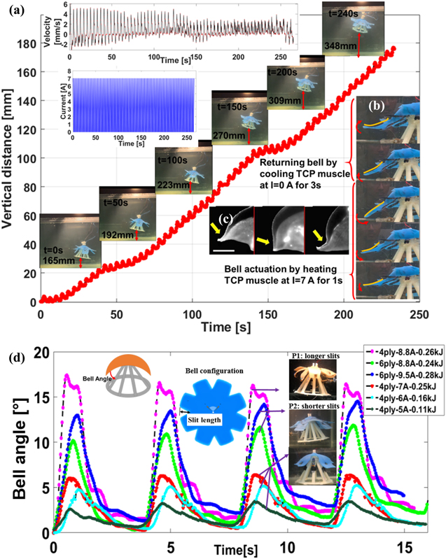
Figure 2. Biomimetic jellyfish swimming test with 6ply TCP: (a) vertical position, velocity, input current, and bell deformation during actuation and cooling; (b) bell deformation of jellyfish robot during swimming compared to (c) deformation of bell margin during swimming in real jellyfish species (Aurelia aurita) [37]. (d) Result of the actuation of one bell segment underwater with 4ply and 6ply TCP muscles (length L = 95 mm, 800 g pre-tension) at different input powers.
Download figure:
Standard image High-resolution imageThe input power for heating the actuator is another important variable to provide efficient bell deformation for swimming. To study different actuation characteristics, the bell actuation angle is compared using 4-ply and 6-ply TCP muscles at different input powers (heating energy). Three different bell geometries are studied here. As shown in figure 2(d) the 6-ply muscle provided a maximum deflection of 13° at 9.5 A, which is twice the bending provided by 4-ply muscle at 7 A. It is important to note that each muscle can withstand a maximum current input depending on its resistance before breaking; this will be discussed further in the TCP characterization section. Due to the surface area of the silicone flap and its connection to the center, the flap experiences a small resistance to bending. As the slits extend toward the center and the bell section separates farther from the center (longer slits), it can move more freely and bend more effectively. As shown in figure 2(d), the bell with longer slits (P1) bent up to 16° when an input current of 8.8 A supplied to the 4-ply TCP actuator. However, this long slit bell configuration is not capable of swimming because if the bell components are separated, it will allow the water to slip between them (on the sides) and the pressure gradient reduces under the bell.
The total electrical power applied to Poly-Saora for swimming was 600 W. In general, the TCPs consume lower power while actuating in the air. The high energy consumption is attributed to the fact that the TCP muscles are used underwater. In general, the TCP has much lower power consumption while actuating in the air. When the TCP submerged in water, the increase in input power is necessary to reach the actuation temperature needed to move the muscle due to the rapid cooling of the muscle. Moving forward, isolating the muscles from the water will decrease power consumption. This can be done by circulating water, which is isolated for the surrounding. More work should be done on the material side to reduce power consumption.
This is the first iteration of the robot. The goal here is to test this new actuation technology for the robot and determine the behavior, and possibly optimize the robot in future. The current actuation frequency of the robot is 0.25 Hz, which is lower than the real jellyfish (1.1 Hz) [38]. However, it is still a higher TCP actuation frequency compared to other works that used the same actuators in dry state. We have not used an active coolant in the channels and those are left for future works. TCP actuators can operate at higher frequency 5–7 Hz [25]. However, we are not concerned about the speed at this time considering the number of variables that we need to study. The issue of frequency is important in some applications and needs further study.
3.2. TCPAg characterization by actuating underwater
In this section, we present the results of several experiments that were performed on the 6-ply TCP actuator in water. The length of the muscle is 95 mm (the same length used in the robot for swimming), the resistance R is 2.5 Ω, and the diameter D is 2.4 mm. The aim of this test is to study the parameters of the actuator under different conditions. Figure 3(a) shows a snapshot of the different structures of the actuators that can be fabricated using the method explained earlier. Figure 3(b) shows a schematic diagram of the experimental set up for testing. A cylinder filled with 5.5 gallons of water is used to submerge the muscle. Calibrated weights are attached to the bottom of the actuator in the water and the top end is fixed. Copper wires are connected to both crimps on the ends of the actuator and to the DC power supply, which is located next to the setup. A thermocouple is connected around the midpoint of the actuator to measure the temperature profile during the heating and cooling cycles. NI 9219 is used to measure the output voltage and the temperature, and an open source tracking program (tracker physics) is used to capture the displacement from a video recording. The 6-ply TCP muscle is tested by hanging a 50 kPa load (900 g mass) on one end and fixing the other end while it is fully submerged in water. Typically, when the TCPs are used in air, they are actuated at low frequencies due to the time requires for cooling. However, the actuation frequency can be increased to 10 Hz when the muscle is directly actuated in water due to cooling effect. The properties of the TCP muscle actuated in the air and in the water are compared in table 2. The maximum displacement and temperature of the muscle are measured at two different frequencies underwater as shown in figure 3. The muscle was actuated with a power input at almost 3 times more than the standard power consumed in an open-air environment. The maximum actuation strain produced at 0.1 Hz and 0.25 Hz frequencies is 8% and 5%, respectively as shown in the 1st row of figures 3(c) and (d). There is a bias for both frequencies due to insufficient cooling (9 s at 0.1 Hz and 3 s at 0.25 Hz). The temperature of the muscle remained under 60˚C as shown in the 2nd row of figures 3(c) and (d) while actuating in water and therefore, the actuation strain is less than when the actuation is in air. It is reported that the temperature of the actuator would reach 140˚C when it is actuated in air [39]. This result can be compared to Wu et al [40] who reported 14% stroke for a 2-ply muscle in the air with an input power of 2.15 W cm−1 heating for 1 s. It is observed that if the frequency increases to values higher than 1 Hz, there is a sudden drop in the displacement with a high bias that will affect the efficiency of the muscle. The sampling rate for temperature, voltage and current data shown in figures 3(c) and (d) was 10 Hz while the displacement was analyzed by Tracker (open source video analysis) software and the samples were read at 2.5 Hz.
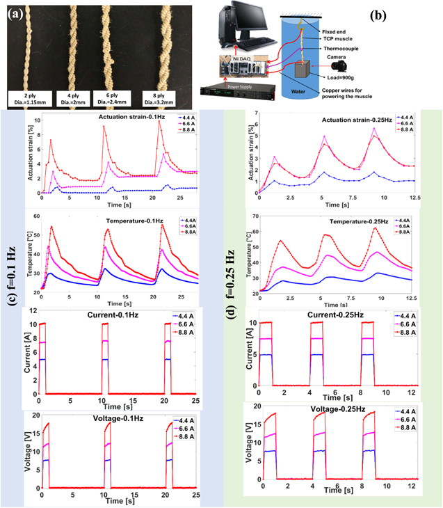
Figure 3. Characteristics of TCP muscles: (a) multi-ply TCP muscles, (b) underwater characterization experimental set up. Characteristics of 6ply TCP muscle in water carrying 900 g load and actuated at an input current of 4.4, 6.6 and 8.8 A: (c) at frequency = 0.1 Hz (1 s heating and 9 s cooling) and (d) at frequency = 0.25 Hz (1 s heating and 3 s cooling).
Download figure:
Standard image High-resolution imageTable 2. Properties of the 6-ply TCPAg used in one bell of Poly-Saora jellyfish while swimming.
| Parameter | Value | |
|---|---|---|
| Material | Silver coated nylon 6,6 | |
| Mass (measured using high precision scale) | m = 0.841 g | |
| Type of actuation | Electrothermal | |
| diameter | D1 = 2.4 mm | |
| Length of precursor fiber | L = 95 mm | |
| Specific heat capacity | Cp = 1700 J Kg−1 °C−1 | |
| Resistance | R1 = 2.5 Ω | |
| Pretension (grams) | W = 800 g | |
| Actuation environment | Air | Water |
| Current | Ia = 2.2 A | Iw = 7.5 A |
| Voltage | Va = 5.5 V | Vw = 20 V |
| Heating time | th = 15 s | th = 1 s |
| Cooling time | tc = 45 s | tc = 3 s |
| Heating energy | Eh = 181.5 Ja | Eh = 160 Jb |
| Actuation frequency (While swimming) | f = 0.017 Hz | f = 0.25 Hz |
| Duty cycle | Dc = 25% | Dc = 25% |
| Lifecycle of TCP | η = 200 cycles [31] | η = 787 cycles |
aThe actuation strain at 181.5 J heating energy in air condition is ∼22%. bThe actuation strain at 160 J energy in water condition is ∼8%.
In order to show the consistency of the muscle, a lifecycle test was conducted for the 6-ply TCP actuator with the same length (95 mm) directly exposed to the water. The jellyfish structure is fixed inside the water tank. Test results such as the time domain plots of the actuation strain, temperature change, input current and output voltage of the 6-ply TCP muscle are shown in figure 4. The 6-ply TCP continuously operated for a total of 787 cycles. This result shows the uniform behavior of the muscle in a number of cycles as shown in the amplitude of the actuation strain plot at the bottom left of figure 4. Here, the actuation strain amplitude maintained at an average of 10%. These results are very dense due to the long test time, thus we showed actuation strain, actuation temperature, input current, and output voltage zoomed sections between 346th and 356th cycles (an equivalent time of 40 s) in the inset of each figure. It is important to note that this power consumption of the muscle is still 3 times higher than the one used in standard air actuation. A bias can be observed, which increases as the number of cycles increases due to the heat accumulation of the surrounding water. As it is shown in figure 4, the voltage is increased as the number of cycles increased and therefore, the resistance of the muscle increased (V = RI). This is due to the reaction between the silver particles and the water. By passing the electrical current through the silver coated nylon 6,6, the silver particles react to the water and oxidize. It is also observed that prolonged actuation of the muscle in water results in change in color of the muscle to dark brown due to this reaction in water. The training of the muscle is done in the air and then the actuation was done in a different environment (water). The obtained results suggest a different training procedure for annealing the muscle in water, which needs further investigation in the future. Saharan et al [41] reported a lifecycle of 200 at an input voltage of 11 V for 25 s (0.04 Hz) with a 20% duty cycle for 2-ply TCP. A comparison of the characteristics of TCP muscle in air and water shows that the strain actuation decreased in the water while the lifespan of the muscle increased significantly, and the muscle can actuate at much higher frequencies (up to 10 Hz) due to active cooling. Coiled nylon wrapped with multiwall nanotube (MWNT) can sustain a million cycles before failure [25], however adding MWNT will add cost. Therefore, we studied the TCPs (6-ply) for the lifecycle.
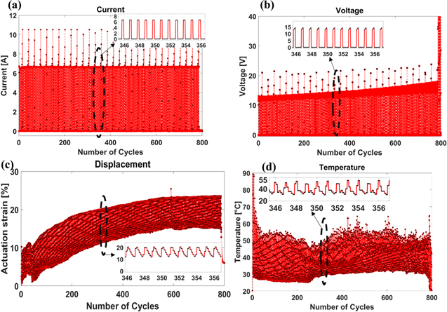
Figure 4. Life cycle test of 6ply TCP at 6.5 A current and frequency of 0.25 Hz (1 s heating and 3 s cooling): (a) input current; (b) output voltage, (c) actuation strain (output) and (d) actuation temperature.
Download figure:
Standard image High-resolution image3.3. Soft bell characterization
Ecoflex 00-30 is used to prepare the soft segment of the jellyfish in this study. For this study, instead of using the TCP actuator to bend the bell, calibrated weights are used ranging from 10 g to 700 g. The muscle is removed from one channel and instead, the spring steel is loaded through the pulley system by calibrated weights to measure the deflection angle on each load as shown in figure 5(a). The flat spring steel plates are used to further control the stiffness of the bell and maintain the structural rigidity. Each bell segment is embedded with one spring steel. The length and width of the spring steel is 70 mm and 13 mm, respectively. The thickness of the spring steel used for Poly-Saora robotic jellyfish is 0.1 mm, which provides enough stiffness for the bell to deform by actuating the TCP and returning it back to its original position when the muscle stops actuating.

Figure 5. Bell deformation mechanism and analysis, and the effect of pre-tensioning the TCP on bell deformation in water: (a) Schematic of bell deformation mechanism, (b) bell curvature (exaggerated), (c) deformation angle measurements (θ), and (d) the angular displacement of the bell with and without soft compartment versus vertical load compared the theoretical results from the cantilever beam equation.
Download figure:
Standard image High-resolution imageConsidering the spring steel at the initial position as a straight beam, its curvature is proportional to applied moment (assuming the moment is dominant) and inversely proportional to bending stiffness (product of Young's modulus and moment of inertia of the beam cross-section) [42]. In general, the radius of the curvature ( ) is obtained by the following equation:

where  is the length of the beam and
  is the angle shown in figure 5(b). The relation between the spring steel radius of curvature (
 ) and wire (
 ), the length of the spring steel
  and the length of the section of the wire that is passed through the wire holders and parallel to the spring steel (
 ) can be written as:

The wire holders keep the wire at a uniform offset distance of  from the spring steel. For simplification, we assume that the number of holders are enough to create curved wires, similar to the curve obtained from the spring steel. Therefore, the relation between the wire radius of curvature and the spring steel radius of curvature is:

Finally, the spring steel radius of curvature at each load can be calculated by:

Initially, the length of the spring steel and the length of the wire that is parallel to the spring steel are equal, as shown in figure 5(a). By increasing the load (m), the wire is shortened which resulted in curving the bell. The effect of the wire holder, due to the offset distance on the curvature, is an important parameter as shown in equation (4) and also stated in Villanueva et al [42].
The rotation angle of the bell for each load is measured by considering the tip position at each load as shown in figure 5(c). By decreasing the thickness of the bell, a lower force is required to bend the bell. Figure 5(d) shows the displacement of the bell with 3 mm in thickness and 120 mm in length under different loads. Increasing the thickness and stiffness of the bell requires a more powerful actuator or an array of muscles for each bell, which in return will require greater energy to operate the robotic structure. Deflection analysis is done to gain an understanding of the force-deflection characterization of the bell. The bell bending is due to the deflection of the spring steel, which can be assumed as a cantilever beam effect with transverse load at the tip. However, adding the silicone bell will affect the stiffness. In this study, we assumed the spring steel as a rectangular cantilever beam under direct compression and bending forces. Due to the high ratio of the length to the thickness of the spring steel, the shear stresses can be neglected. The spring steel restores the deflection and recovers to its straight shape, but the effect of the bending moment is the main reason for the deflection. If the bending moment increases in the constant stiffness structure, the beam continues to bend until it fails.
We considered the effect of the load due to the force and moment on the cantilever beam as a combined load. Then, we took the superposition of the deformation due to the combined load as it was done in other studies. The deflection of the beam can be derived from superposition of deformation of cantilever beam with the moment and vertical force at the end [43, 44]:
where  is the deflection angle, Fy is the applied force perpendicular to the spring steel axis at the tip,
  is the force parallel to the beam axis, d is the vertical distance between the spring steel and the wire, M is the bending moment due to the force
 is the length of the spring steel,
  is the elastic modulus (E = 200 GPa for 1095 steel) and I is the moment of inertia (1/12 bh3), which is related to the geometry of the cross section. The resistance of the beam to bending can be measured by flexural rigidity (EI) which depends on the material and geometry [45]. The force angle shown in figure 5(a) is measured as β = 13°. Equation (5) is based on small angle deflection assumption. We determined the deflection angle using this equation (equation (5)). However, it has some deviation with the experimental results as shown in figure 5(d). Therefore, it did not predict the tip deflection without a correction factor, due to the large angle deflection of the beam. This is what we are observing in the results. For simplicity in analysis, correction factors are used to study some variations in small angle assumption and we modified the expression in equation (5) as:

 and
and  are the coefficients that account for only vertical load and moment, or combined loading conditions. The analytical results of spring steel deflection obtained using equation (6) are shown in figure 5(d). When
  = 1 and
  = 0, the deflection is only due to vertical force (
 ). Whereas, when
  = 0 and
  = 1, the deflection is only due to moment due to the horizontal force (
 ). However, the two cases did not provide close results with the experimental (figure 5(d)). A linear multiplication of the angles (
 = 0.02 and
  ), gave a good approximation of the experimental result. The maximum 45° bending suggests that the deflection is high. Therefore, large deflection analysis is required to be performed as it was done in other studies [46–50]. This requires different equations, elliptical integrals and extensive analysis in both theoretical as well as validation. However, it is interesting to see that with some correction factors, the tip deflection is linearly correlated with the angle obtained by small angle assumption. More work should be done to analyze such scenarios and we will investigate this in the future.
Another aspect is the axial loading associated with deflection. The larger component of force, which is parallel to the spring steel axis results in compression loading and buckling. The critical load (  ) for buckling is calculated from equation (7) [51]:

where 
 and
and  are the same as equation (5). The effect of buckling should be considered for calculating the beam curvature since the critical load is very low in this case (0.12 N). Since the applied load is higher than the critical bucking load, more investigation in the analytical equation is needed. There are some related works in other smart materials such as IPMCs [52]. This aspect should be investigated in our future work as well.
Based on the obtained results from the bell actuation using 6-ply TCPs and swimming tests (figure 2(d), green lines, 6-ply at 8.8 A–0.2 kJ energy) presented in the previous sections, the bell should be actuated to reach a minimum of 10° bending angle to provide sufficient propulsion for the jellyfish robot to swim. As shown in figure 5(d), the bell with 3 mm thickness required ∼2 N force to bend 10°. This bending angle can be achieved by a 95 mm TCP muscle with 800 g pretension actuating at a strain of 7%.
The thrust force (T) is dependent on the bell deformation properties (deformation magnitude and actuation frequency) during swimming [53]. However, other forces such as drag force (D), the acceleration reaction of the fluid (G), buoyancy (Fb), momentum changes of the robot (F) and the weight of the robotic structure (W) can affect swimming [5]. The balance of these forces and the relationships with volume change and instantaneous velocity are provided in Villanueva et al 2011 [5]. The trust force is highly correlated with the displaced volume of the cavity of the robot during deformation. This displaced water volume as well as the circulation of the water under the bell are responsible for swimming.
3.4. Effect of TCP pre-tension on the actuation of one bell segment
In this part of the study, we have determined the effect of muscle pre-tensioning to study the actuation strain while operating in the jellyfish structure. It is determined that suitable pre-tensioning is highly important to get the best actuation from the actuator. This is mainly due to the spacing between the coils of the actuator. However, very high pre-tensioning results in the breaking of the muscle during the first actuation cycle. In order to vary the pre-tensioning of the muscle, a longer TCP actuator with a length of 310 mm is chosen to extend the muscle out of the channel. In this case, the pre-tension is varied easily by pulling the muscle and fixing it in a fixture, which corresponds to a load that provides the same effect. Also, using a longer muscle is more beneficial for observation of the maximum bending angle of the bell segment (25°), since longer muscle has higher displacement which can provide a more accurate reading. The best pre-tensioning for TCP muscle is attained at 800 g loading that results in 22.6% actuation strain in air condition at input current of 2.2 A for 15 s. Further experiments revealed that the length of the muscle does not affect the pre-tensioning results and the same results can be interpreted for all lengths. In figure 6, the results of the bell actuation with 6-ply TCP at 3 different pre-tensions of 600 g (low), 800 g (medium), and 1000 g (high) are compared underwater. The muscle is actuated for 1.5 s at 8.8 A. The high pre-tensioning result in almost 25° bending with a higher slope (in a shorter time) in water, however, this pre-tension decreases the lifecycle of the muscle significantly due to the exposure to constant high loading. Due to the stiffness of the 6-ply TCP (calculated as 283 N m−1), fixing the actuator at one end and applying the load to the other end, results in specific values of extension of the TCP. The calculated stiffness is comparable to 4-Ply TCP stiffness, which is mentioned as 98.8 N m−1 by Wu et al [54]. To pre-tension the muscles, the connected bead wire is pulled through a punched hole on the free end of the spring steel at a calculated length of approximately 1.5 cm, and then tied and fixed through the hole. The 1.5 cm is an equivalent of 800 g loading for a 95 mm actuator before pre-tensioning.
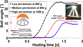
Figure 6. Results of actuation of the TCP at low (600 g), medium (800 g) and high (1000 g) pre-tension. The pre-tensioning is changed by the fixed end of a long muscle (L = 310 mm) outside the channel tube as shown in the plot asset.
Download figure:
Standard image High-resolution image4. Discussion and conclusion
This paper introduced and described a biomimetic jellyfish (figure 1) that uses TCP actuators to swim underwater as shown in figure 2(a). Similar research efforts were presented that used smart materials as their main source of actuation, however, most of them utilized some form of metallic SMAs making the presented work novel since we utilized only polymeric materials to produce actuation. The jellyfish robot is created using a 3D printed body, a silicone bell, and TCP actuators making it almost 95% by volume comprised of polymers. The implementation of the TCP actuators in the 3D printed structure rather than the silicone bell serves as a mechanism to maintain the flexibility of the bell, and also the option to easily change, replace, and vary the pre-tension parameters. TCP actuators showed promising results when it is deployed for underwater actuation. Moreover, TCP muscles were preferred over SMA wires due to higher actuation stroke. We have tried to find the optimized working parameters (frequency, power, and strain) besides some important physical properties of the muscle for actuation such as length and pre-tensioning to generate the best performance of the muscle in the robot. The Poly-Saora jellyfish has the ability to actuate up to eight TCP muscles at once, however, in this case, only four were necessary to swim. The utilization of mainly polymers to create a low-cost actuation mechanism, makes our jellyfish unique and unlike any other conceived. Poly-Saora jellyfish was able to swim 180 mm at speed of 5 mm s−1.
The main goal of the current work is utilization of TCP actuators for swimming motion of a biomimetic jellyfish that consists of a 3D printed structure and flexible bell segment. Several prototypes are tested for tuning the actuation parameter of TCP with the provided geometry to achieve successful swimming. The robot presented here helped us to test several hypotheses. We did not know which parameter could result in swimming before carrying out experiments. The structure itself, the actuation parameters (amplitude, frequency, and the number of cycles), the number of actuated bell segments, the thickness of the bell, the buoyancy and the pre-stress are some of the important factors for vertical swimming. The main hypothesis in this work is that the TCP actuators, when integrated into 3D printed biomimetic structures and flexible substrate, provide a swimming performance if and only if the actuation parameters are tuned with the geometry of the robotic system. We tested several cases and we could not get good performance. The actuation characteristics presented in the summary table (table 1 and the results in figure 2) are the ones that resulted in good swimming characteristics. These are all associated with the fluid circulation under the bell and the geometry of the bell that cased the fluid flow. The other hypothesis in this work is that the actuation pattern of the flexible bell margin significantly affects the swimming performance, i.e. a brief pause during actuation to cool the TCP actuators is essential to allow the flow circulation developed under the bell structure in each swimming cycle.
Future testing and investigation should be focused on creating a fully confined untethered system, that is housed within the 3D printed structure as shown in figure 7. Environmental sensing components such as temperature sensors, sound sensors, IMU (inertial measurement unit) and a camera can be added to enhance the functionality of the robot for underwater exploration and inspection as shown in figure 7(a). Combining these components with a sealed system shown in figure 7(b) consisting of a communication module, onboard battery, and closed loop control can make the jellyfish swim even more effectively while still maintaining the cost effectiveness offered by the TCP muscles and the polymer passive structures. With the addition of these components and a closed loop control system, we would be taking a big step towards a fully autonomous jellyfish with many applications in exploration and research as shown in figure 7(c). A buoyancy control unit and self-contained battery system will also be added to provide autonomy to the robot. Figure 8, shows the prototypes, which were successfully tested for swimming and we have provided a summary video of the experiments. We hope these results stand as an important basis for many researchers who would like to investigate the use of these novel TCP actuators for underwater robotic applications.
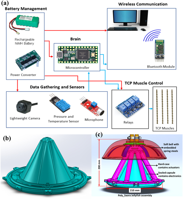
Figure 7. (a) Proposed design circuit for untethering powering and control of Poly-Saora, (b) designed capsule for accommodating electronic components and (c) assembly of the powering and control unit under the robot.
Download figure:
Standard image High-resolution image
Figure 8. Jellyfish prototypes which successfully swim in the water by implementing 6-ply TCP muscle for actuation. The video is available in the following link: https://youtu.be/sDEk2Y38Bzg.
Download figure:
Standard image High-resolution image
Acknowledgments
The authors would like to acknowledge the support of the Office of Naval Research (ONR), Young Investigator Program, under Grant No. N00014-15-1-2503. Part of this work is supported by the Office of Naval Research under Contract No. N68335-18-C-0368.