
Abstract
This study proposes a cross-coupled dual-beam structure for energy harvesting from vortex-induced vibrations (VIV) induced by wind flows in different directions. A series of wind tunnel tests are conducted to investigate the performance of the proposed energy harvester subjected to the wind load with various speeds and directions. The upper and bottom piezoelectric beams can generate a maximum power output of 6.77 μW and 56.64 μW, respectively. The dominant operation frequencies in different directions are different which indicates a potential broadband capability. A parametric study is performed to reveal the effect of the dimension of the bluff body on the performance of the proposed energy harvester.
Export citation and abstract BibTeX RIS
1. Introduction
In the past few years, wind energy harvesting using piezoelectric materials has attracted numerous research interests for the ease of implementation and the great potential as sustainable power supply for MEMS (Microelectromechanical Systems) and WSNs (Wireless Sensor Networks). According to different aerodynamic phenomena employed, wind energy harvesters can be classified into the following several types: galloping based [1–3], vortex-induced vibration based [4–6], flutter based [7] and wake galloping based [8]. The basic concepts of these aerodynamic phenomena and their applications in energy harvesting have been summarized and well introduced in the review papers [9, 10].
Conversion efficiency is usually one of the most important concerns in the design of energy harvesting systems. In the field of wind energy harvesting, various strategies have been proposed to improve the power output including optimizing the aerodynamic contour, the energy harvesting interface circuit and the structure constructions [11–18], introducing an electromechanical coupling amplifier [15] employing nonlinear components [19–21], utilizing different concurrent vibration sources [22, 23]. On the other hand, multi-directional energy harvesting capability is always highly desired as well, since the ambient excitation quite possibly varies in terms of the direction. Several studies have been devoted to multi-directional energy harvesting from the base excitation. Zhao et al [24] designed an arbitrary-directional vibration energy harvester by using magnetically coupled flextensional transducers. The performance of the designed energy harvester was experimentally evaluated: under the excitation in several representative directions, the average maximum output power ranged from 10 μW to 174 μW. Zhang et al [25] proposed an impact-based piezoelectric energy harvester consisting of a rolling bead embraced in a bracket with a spring connection. The experiment showed that the proposed energy harvester can effectively operate under the excitation in different directions. Xu and Tang [26] realized multi-directional energy harvesting by using a piezoelectric cantilever-pendulum structure with 1:2 internal resonance. The underlying mechanism behind the multi-directionality of the cantilever-pendulum structure is the energy interchange between different vibration motions. Wu et al [27, 28] designed a pendulum system consisted of a mass suspended by a spring that was made of multiple binder clips bonded with piezoelectric transducers. The system was carefully designed to possess the 1:2 resonance feature as well for enabling multi-directional energy harvesting. Fan et al [29] presented a hybrid energy harvester that can scavenge energy from bi-directional base excitation. The hybrid energy harvester was actually a combination of two sub-energy harvesting systems: a conventional cantilevered piezoelectric beam and an electromagnetic energy harvester. The two sub-systems operated in different directions and the bi-directionality was achieved by integrating the two sub-systems through magnetic coupling. To the authors' best knowledge, research on the development of multi-directional wind energy harvesters is still relatively rare. Since the direction of the natural wind is featured with even higher uncertainty, to achieve multi-directional wind energy harvesting is of great importance but still remains as a big challenge. To address this issue, in this paper, we propose a cross-coupled dual-beam structure for harvesting energy from wind flows in different directions.
2. Design
Figure 1 shows the schematic of the proposed energy harvester. Two beams bonded with piezoelectric transducers (PZT-5, Jia Yeshi. Corp.) are jointed crosswise. A circular cylinder bluff-body is attached to the free end of the bottom cantilever beam with the length and cross-section diameter of L0 = 120 mm and D0 = 32 mm, respectively. The other detailed geometric and material parameters of this physical prototype are listed in the appendix. A hot-wire anemometer and a digital oscilloscope are used to measure the wind speeds and the voltage output, respectively. It should be noted that the cylinder is placed along the longitudinal direction of the bottom beam. However, in most of previous studies, the cylinder is often aligned perpendicular to the beam [1, 4, 6]. A recent research by Dai et al [30] compared the two different orientations of the bluff body and provided the guideline for the selection of the configuration for different situations depending on the wind speed. The main reason here is that the proposed energy harvester is designed for the multi-directional purpose, the axisymmetric installation is to ensure that the bluff body can be induced by the wind from any directions.
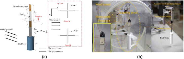
Figure 1. (a) Schematic of the proposed energy harvester; (b) the physical prototype in the wind tunnel.
Download figure:
Standard image High-resolution imageThe natural frequencies of the energy harvester corresponding to the fundamental bending modes in the y and x directions are 4.74 Hz and 12.23 Hz, respectively. The physical prototype is mounted on a rotatable auxiliary transom that is placed in a wind tunnel with a diameter of 400 mm (as shown in figure 1(b)). The incoming wind direction can be adjusted by tuning the rotatable auxiliary transom. A series of wind tunnel tests under a low-turbulence flow with a turbulence intensity less than 0.01 are conducted to evaluate the actual performance of the proposed energy harvester. The upper beam is set first parallel then perpendicular to the incoming wind direction, as demonstrated in figure 1(a), where α is orientation angle of the proposed energy harvester. In the experiment, the orientation angle of the proposed energy harvesting is controlled to equivalently realize the change of the wind attack angle.
3. Results and discussion
Figure 2 reveals the effect of the wind speed U on Vrms under the open-circuit condition at two different wind attack angle  = 0° and
  = 90°. As shown in figure 2(a), at α = 0° (Case A), there is no Vrms response from the bottom beam. In the experiment, it is observed that below the joint point, the entire bottom beam behaves as an extended part of the bluff body and vibrates like a rigid body in the x-direction, moving synchronously along with the bluff body. Therefore, the piezoelectric transducer bonded on the beam bears nearly no mechanical strain, and almost no voltage is generated. The upper beam, however, performs well with a maximum Vrms of 5.98 V under the wind speed of 1.0 m s−1. At α = 90° (Case B), the situation turns out to be the opposite as shown in figure 2(b). The bottom beam can effectively generate a maximum Vrms of 11.78 V under the wind speed of 2.646 m s−1. However, since the bending stiffness of the upper beam in the x-direction is very large, it acts as an extension of the fixed end. It can thus be understood why the upper beam does not vibrate and the bonded piezoelectric transducer generates almost no voltage output.
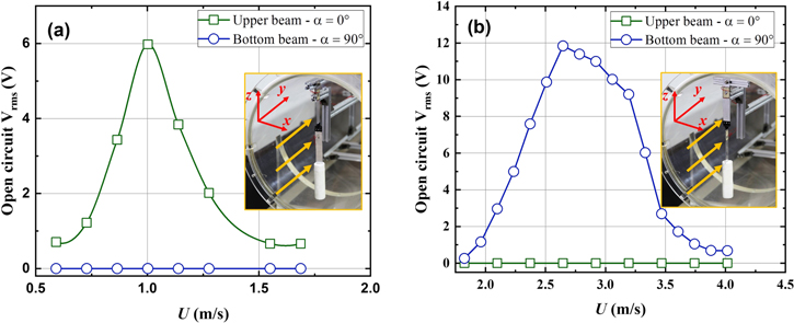
Figure 2. Open-circuit Vrms responses from the upper and bottom piezoelectric beams of the proposed energy harvester with varying U at (a) α = 0° and (b) α = 90°.
Download figure:
Standard image High-resolution imageWhen the vortex shedding frequency gets close to the resonant frequency, it becomes synchronized with the frequency of oscillation, at the same time, self-sustained large-amplitude oscillations occur. The wind speed range within which such synchronization phenomenon occurs is the so-called lock-in region. With the increase of the wind speed, the vortex shedding frequency first approaches then deviates away from the natural frequency of the energy harvester. This explains why the power output from the energy harvester first increases then decreases. It is can be observed that the lock-in region of Case B (1.82 m s−1 ≤ U ≤ 4.0 m s−1) is much wider than Case A (0.59 m s−1 ≤ U ≤ 1.69 m s−1), that is to say, the lock-in bandwidth of Case B (2.18 m s−1) is about twice of that of Case A (1.1 m s−1). Meanwhile, the maximum Vrms of Case B is also larger than that of Case A. Overall speaking, as an entire system, the proposed energy harvester could effectively operate over a broad wind speed range, i.e., 0.59 m s−1 ≤ U ≤1.69 m s−1 and 1.82 m s−1 ≤ U ≤ 4.0 m s−1.
Under the optimal wind speeds determined from figure 2, figure 3(a) shows the variation of the average power output from the proposed energy harvester (Pavg =  /R, the subscript rms denotes root mean square) with the change of the electrical resistance R.
From figure 3(a), it can be noted that for the upper and bottom piezoelectric beams, Pavg reaches the maximum when R = 2.4 MΩ at U = 1.0 m s−1 and R = 0.9 MΩ at U =2.646 m s−1, respectively. Therefore, R = 2.4 MΩ and R =0.9 MΩ are deemed as the optimal load resistances that are used in the rest tests of this study. Though the raw lengths of the two beams are the same, their boundary conditions are different, leading to different resonant frequencies (figure 3(b)) and bending modes (figure 5). With the aid of the developed theoretical model presented in the appendix, it is more easily to understand the difference between the two bending cases which explains why the two different cases have different matching resistances.
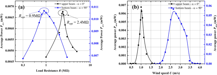
Figure 3. Variations of average power Pave from the upper and bottom piezoelectric beams of the proposed energy harvester with the change of (a) load resistance R and (b) wind speed U.
Download figure:
Standard image High-resolution imageSince the optimal wind speeds are of the most interest, the two piezoelectric beams are shunted to the optimal resistances determined from figure 3(a) for simplicity. Figure 3(b) shows the power output from the proposed energy harvester over a wind speed range that covers the lock-in regions. It is found that the Pave from both the piezoelectric beams gradually increase with the increase of U after the onset of VIV, then reach the respective maximum, and finally decrease when the wind speed further increases. The upper and bottom piezoelectric beams can generate a maximum power output of 6.77 μW and 56.64 μW, respectively. It can be observed from figure 3(b) that the lock-in regions are approximately 0.59 ∼ 1.69 m s−1 and 1.82 ∼ 4.0 m s−1 for the upper and the bottom beams, respectively.
The existence of the two different effective wind speed ranges for energy harvesting is mainly for the reason that the resonant frequencies of the two cases are different. Figure 4 shows the frequency spectra of the open circuit voltage outputs from the upper and bottom piezoelectric beams of the proposed energy harvester for Case A and Case B under U = 1.0 m s−1 and U = 2.646 m s−1, respectively. The frequency spectrum analysis results are also provided in figure 4. It can be seen that the resonant frequency of Case A (fn = 4.74 Hz) is lower than that of Case B (fn = 12.23 Hz). Since in Case B the upper beam can be deemed as an extension of the fixed end, the bottom beam can thus be regarded as a conventional cantilevered beam with a tip mass. The fundamental transverse vibration mode of the proposed energy harvester in the y direction is presented in figure 5(b) to verify this speculation. With this assumption, one can easily derive the resonant frequency of Case B. However, in Case A, as aforementioned the bottom beam acts as an extended part of the bluff body, thus, it contributes to the effective tip mas of the upper beam (the fundamental bending mode corresponds to Case A is presented in figure 5(a)). Moreover, considering the parallel axis theorem, since the upper beam is connected to the bluff body through the bottom beam with a certain non-zero length, the moment of inertia of the bluff body about the tip of the upper beam obviously becomes larger as compared to that in Case B. Therefore, due to the increase in the effective tip mass and the moment of inertia of the bluff body, the resonant frequency of Case A is unsurprisingly lower than that of Case B. To give a quantitative analysis regarding the natural frequencies related to these two fundamental bending modes, a theoretical model is developed and presented in the appendix. On the basis of the established theoretical model, the two fundamental natural frequencies corresponding to the two bending modes in the x and y directions are predicted as 4.40 Hz and 12.61 Hz, respectively, which are very close to the experimental results (i.e., 4.74 Hz and 12.23 Hz).

Figure 4. Frequency spectrum analysis for open circuit Vrms from the upper and bottom piezoelectric beams of the proposed energy harvester.
Download figure:
Standard image High-resolution image
Figure 5. Fundamental transverse vibration modes of the proposed energy harvester in the (a) x direction and (b) y direction.
Download figure:
Standard image High-resolution imageTo further investigate the effect of the bluff body on the multi-directional energy harvesting performance of the proposed cross-coupled dual-beam structure, three bluff bodies with different sizes are tested and compared. The results of the Vrms response under the open-circuit condition with different bluff body length L are presented in figure 6. For L = 0.5L0 as shown in figure 6(a), the lock-in region of the upper beam operating under the condition of Case A and the bottom beam operating under the condition of Case B are respectively 0.88 m s−1 ≤U ≤1.51 m s−1 and 2.98 m s−1 ≤ U ≤ 4.12 m s−1. The corresponding maximum voltage outputs of the upper beam and the bottom beam are respectively 1.887 V and 7.731 V under the open circuit condition. For L = 0.67 L0, the lock-in region of the upper beam in Case A and the bottom beam in Case B are 0.75 m s−1 ≤ U ≤ 1.48 m s−1 and 2.62 m s−1 ≤ U ≤5.02 m s−1, respectively, as shown in figure 6(b). The maximum open circuit voltage outputs of the upper and bottom beams are respectively 3.073 V and 10.251 V. For L = L0, the lock-in region of the upper beam in Case A and the bottom beam in Case B are 0.59 m s−1 ≤ U ≤ 1.69 m s−1 and 1.82 m s−1 ≤ U ≤4.0 m s−1, respectively, as shown in figure 6(c). The maximum open circuit voltage outputs of the upper and bottom beams are respectively 5.977 V and 11.841 V.
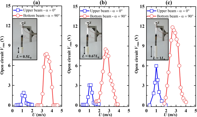
Figure 6. Open circuit Vrms of the proposed energy harvester with different lengths of bluff body: (a) L = 0.5L0, (b) L = 0.67L0 and (c) L = L0.
Download figure:
Standard image High-resolution imageBy comparing the results of the three case studies (L = 0.5L0, 0.67L0 and L0) presented in figures 6(a)–(c), it can be found that with the increase of the length of the bluff body, the onset wind speed generally decreases. The potential explanation is that the longer the bluff body, the farther away the centroid from the clamped end of the system, leading to the increase of the rotational inertia. The resonance frequency of the system thus becomes lower and the onset speed consequently decreases. Moreover, the maximum open circuit Vrms from both the upper and bottom piezoelectric beams exhibit an increasing trend with L. This is because the longer the bluff body, the stronger the aerodynamic force induced by the wind flow. In general, it can be seen that the proposed energy harvester can effectively generate power output by either the upper or the bottom beams within different wind speed ranges, depending on the bluff body size.
4. Summary
In summary, this paper has proposed a cross-coupled dual-beam structure for scavenging energy from wind under various incoming directions. Experiments have been conducted to validate the multi-directional capability of the proposed energy harvester. In-depth investigations have been performed to further explore the characteristics of the proposed energy harvester. It is found that different directional wind can arise the vortex-induced vibration of different beams. Besides, it is observed that the dominant operation frequencies of the upper and the bottom beams are different, corresponding physical explanations have been provided. Moreover, the operational wind speed ranges of the two beams are different, enabling the proposed energy harvester to cover a much broader operation wind speed range than traditional wind energy harvesters. The discussions on the underlying mechanisms of the proposed energy harvester can inspire some other multi-directional designs. This work can provide some guidelines for the study of future multi-directional wind energy harvesters.
Acknowledgments
The authors gratefully acknowledge the support provided by the National Natural Science Foundation of China (No: 51606171), China Postdoctoral Science Foundation (No. 2019M652565) and Seed Funding of University of Technology Sydney (No. 2232299).
Appendix
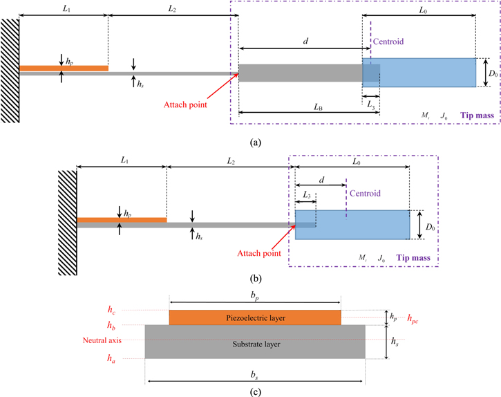
In this appendix, a theoretical model is developed for predicting the fundamental natural frequencies corresponding to the bending modes of the proposed energy harvester in the x and y directions. Figures A1(a) and (b) show the diagrams of the cross-coupled dual-beam system bending in the x and y directions, respectively. As explained previously, when the proposed system transversely vibrates in the x direction, the bottom beam almost does not deflect in the low frequency range since its bending stiffness in the x direction is very large as compared to that in the y direction. In this case, the upper beam acts as the dominant bending beam and the bluff body together with the bottom beam play the role as the tip mass. When the proposed system vibrates in the y direction, the bottom beam becomes the dominant bending beam. Since the upper beam acts as an extension of the base in this case, the left hand side of the bottom beam can be regarded as under the clamped condition (figure A1(b)).
Figure A1. Diagram of the cross-coupled dual-beam system bends in the (a) x-direction; (b) y-direction; (c) the cross-section view of the dominant bending beam.
Download figure:
Standard image High-resolution image
The thickness and the length of the dominant bending beam are hs and (L1 + L2), respectively. It is covered by a piezoelectric layer with the thickness of hp and length of L1. The subscripts s and p denote the substrate material of the bending beam and the piezoelectric layer, respectively. The subscript 1 and 2 represent the beam sections with and without piezoelectric coverage, respectively. A cylinder bluff body of length L0 and cross-sectional diameter D0 is attached at the tip of the bottom beam. A small portion (L3) of the bottom beam is inserted into the bluff body. The bluff body together with the small portion of the bottom beam are considered as the tip mass. The centre of gravity of the tip mass lies at a distance of d from the attach point.
Figure A1(c) shows the cross section view of the dominant bending beam. ha is the coordinate of the bottom of the substrate layer in the thickness direction by setting the original point on the neutral axis. The widths of the host beam and the piezoelectric layer are bs and bp, respectively. hb and hs are the distances from the bottom and the top of the piezoelectric layer to the neutral axis, respectively. They can be calculated according to the material and geometric properties of the beam by the following relations:
in which, Es/p is the material Young's modulus. The governing equations of the beam regarding the sections with and without the piezoelectric layer are written as:

where  represents the transverse deflection.
  is the mass per unit length.
  is the bending stiffness. These parameters can be calculated by using the geometric and material properties of the beam.
Assuming the solution to equation (A2) to be in the form as  the governing equation of the beam is then simplified as:

where  is the mode shape. The solutions to equation (A4) are assumed in the form as follows:
in which  k = 1/2. The boundary conditions (i.e., clamped, free and continuities) are mathematically expressed as follows:
where  is the moment of inertia of the tip mass about the axis that passes through the attach point. By substituting equation (A5) into equation (A6) and after some rearrangement, then letting the determinant of the coefficient matrix to be of zero in order to have a non-trivial solution, one obtains:
where
Solving equation (A7) yields the natural frequencies of this cantilevered beam with a tip mass. In the case of figure A1(a), the bottom beam should be taken into account as a part of the tip mass. The tip mass  is thus:

where  and
and  are the masses of the bottom beam and the bluff body, respectively. The distance from the attach point to the centroid of the tip mass can then be calculated as:

The moment of inertia of the tip mass that consists of the bottom beam and the bluff body can be calculated as:
where  and
and  in which
  is the width of the bottom beam. In the case of figure A1(b), the corresponding d, Mt and J0 can be derived as:


where ![${J}_{3}=\left[{M}_{B}{L}_{3}\left({L}_{3}^{2}+{h}_{s}^{2}\right)\right]/\left(12{L}_{B}\right).$](https://content.cld.iop.org/journals/0964-1726/28/12/12LT02/revision2/smsab5249ieqn17.gif) For the physical prototype investigated in this paper, the geometric and materials papers are listed in table 1. Using the developed method, the fundamental natural frequencies corresponding to the two bending modes are calculated as 4.40 Hz and 12.61 Hz.
For the physical prototype investigated in this paper, the geometric and materials papers are listed in table 1. Using the developed method, the fundamental natural frequencies corresponding to the two bending modes are calculated as 4.40 Hz and 12.61 Hz.
Table 1. Geometric and material properties of the physical prototype.
| Parameters | Value | Unit |
|---|---|---|
| Substrate beam—Aluminium | ||
| L2 | Upper Beam—10.5 | cm |
| Bottom Beam B—7.3 | ||
| L3 | 3.2 | cm |
| LB | 13.5 | cm |
| bs | 2 | mm |
| hs | 0.5 | mm |

|
2750 | kg m−3 |
| Es | 70 | Gpa |
| Piezoelectric layer—PZT 5A | ||
| L1 | 3 | cm |
| bp | 2 | mm |
| hp | 0.2 | mm |

|
7800 | kg m−3 |
| Ep | 52 | Gpa |
| d31 | −190 × 10−12 | m V−1 |

|
1.594 × 10⁻⁸ | F m−1 |
| Bluff body—Foam | ||
| L0 | 12 | cm |
| D0 | 1.6 | cm |

|
18 | kg m−3 |