
Abstract
Giant magnetostrictive materials (GMM) can be integrated in actuator or sensor applications. The design of these systems is optimized based on a good knowledge of the material properties and conditions of use. Terfenol-D exhibits the greatest room temperature strain among commercially available GMM, however, its magneto-elastic behavior is very sensitive to pre-stress level. In this work, the design of an experimental setup dedicated to the characterization of GMM magneto-mechanical behavior under constant stress is described. A major difficulty is to master the mechanical boundary conditions while the sample is subjected to dynamic magnetic loading. The dynamic stress experienced by the sample is connected to the magnitude of the magnetostriction strain, the stiffness of the sample and the stiffness of the characterization setup. Results show that an appropriate setup is able to reduce the dynamic stress variations induced by magnetic excitation variations below 0.1 MPa, while this dynamic stress can reach up to 20 times the magnitude of the applied stress when the control system is not used. With the boundary conditions being controlled, magnetic and magnetostrictive behavior of Terfenol-D are characterized under various uniaxial compressive stress levels, from the stress-free conditions to 90 MPa. By comparing the results obtained under controlled and non-controlled stress conditions, it is shown that uncontrolled boundary conditions can be responsible for errors of several percent on the magnetic induction measurement. The measurement of strain is even more sensitive to the boundary conditions, with errors up to 40% and 30% on the longitudinal and transverse strains, respectively. This work highlights the utmost importance to control the boundary conditions in order to characterize the magneto-mechanical behavior of GMM.
Export citation and abstract BibTeX RIS

Content from this work may be used under the terms of the Creative Commons Attribution 3.0 licence. Any further distribution of this work must maintain attribution to the author(s) and the title of the work, journal citation and DOI.
1. Introduction
Smart materials are widely used for sensor or actuator applications. In applications such as low voltage actuators, large force actuators, high power low frequency transducers or structural vibration control applications, giant magnetostrictive materials (GMM) can be particularly interesting. Among GMM, bulk Tb0.3Dy0.7Fe1.92 (Terfenol-D) presents a large room temperature strain at relatively low magnetic field (below 40 kA m−1), good magneto-mechanical coupling factor, high energy density and fast response [1–6]. However, this behavior is highly nonlinear and very sensitive to mechanical loading [7–13]. With structural design in view, accurate models are needed to predict material properties under stress and to propose adapted design of Terfenol-D devices. Different modeling approaches have been proposed to describe magneto-elastic behavior of Terfenol-D under stress [14–18]. Whatever the modeling approach used, it is essential to appropriately characterize the material behavior to be able to accurately identify the material parameters introduced in the numerical modeling.
Various experimental setups have been used for the experimental characterization of Terfenol-D under mechanical stress. For example, changes in magnetic and magneto-mechanical properties of grain-oriented Terfenol-D samples have been studied, under pre-stress by Moffet et al using hydraulic pressurization [2], and after cycling by Prajapati et al using an electromechanically driven machine [19]. In these works, control of loading boundary conditions or magnetic excitation was not discussed, but accurate measurement of pressure has been performed using a Bourdon tube and a pressure gauge, respectively.
Several authors have designed experimental setup controlling magnetic field (by the current supplied) and loading boundary conditions. Jiles et al [20, 21] reported magnetostriction studies of oriented Terfenol-D. The stress was applied and controlled by a stepper motor. Kvarrsjö et al [22] built an experimental set-up able to produce magnetic field and mechanical stress independently. A control unit was connected to a hydraulic system to apply and control stress. Similarly, Pei et al [23, 24] studied the magneto-elastic behavior of Terfenol-D alloys and oriented materials. In this setup, the mechanical force can be applied at any fixed angle with the magnetic field. The mechanical force measurement was fed back to the hydraulically driven system to adjust the force loading applied to the specimen. Displacement control is sometimes preferred to stress control. Yoffe et al [25] studied the magneto-mechanical response of epoxy-base Terfenol-D for stress sensing applications. Control of displacement rate was ensured by the hydraulic machine that applies pre-stress. Galopin et al [26, 27] designed a magneto-elastic behavior measurement device in which the servo-control was configured to control the position of the crosshead. A common link to all these works is to control the loading boundary conditions using the same system that applies the pre-stress levels. Hence these systems must apply a high level of stress and ensure fast control of loading boundary conditions at the same time. While a good control is very difficult to ensure under these conditions, authors seldom qualify it.
Another way to impose constant pre-stress is to use a dead weight stand. Garcia et al [28] designed a temperature and strain (axial and transverse direction) monitoring system for Terfenol-D with Fiber Bragg grating sensors under magnetic field and low static pre-stress (up to 221 kPa). Compression stress was applied by means of 1 kg loading. Wun-Fogle et al [29] used weights on a lever arm to apply a compressive load (up to 88 MPa) on the sample and generate a magnetic field at low frequency thanks to a classical coil. A linear variable differential transformer was used to measure the displacement. In these two works, the magnetic field was not controlled, but the level of stress was assumed to be constant. Sandlund et al [30] measured magnetostriction, magnetization and Young's moduli of a Terfenol-D composite under compressive stress (up to 16 MPa). Stress was applied by adding fixed weight to a platform attached to the upper surface of the rods. In addition, magnetic excitation was controlled by a computer-controlled feedback. Similarly, Valadkhan et al [31] developed a test rig for measuring magnetostriction under stress (up to 12 MPa). The compression was supplied by a set of washer springs and the magnetic field was controlled by the current. It was assumed that these springs were soft enough to consider a constant compression force for each test. The force of the springs was adjusted by a bolt on top of the test rig. Longitudinal strain was measured using an optical encoder.
All these works result in significant differences in the measurement of the magneto-mechanical behavior of Terfenol-D. These differences are due to different compositions of the material tested [32], but also to imperfect control of magnetic field and mechanical preload [9], especially for GMM. However, little interest is shown in the quality evaluation of current or stress control. Little is said about the homogeneity of the applied stress and field, and the measurement errors are seldom evaluated. Moreover, transverse magnetostriction is not often reported under stress.
This work deals with the characterization of the magneto-elastic behavior of Terfenol-D with a specific focus on the characterization setup and on the role of loading boundary conditions on the measurement results. In the first part, the characterization setup is described, allowing the simultaneous control of magnetic field and stress. Data acquisition and control systems are presented, and a demagnetization procedure is developed. In the second part, the experimental setup is used to characterize the magneto-mechanical behavior of Terfenol-D under constant stress. In the third part, the influence of loading control conditions is studied and discussed.
2. Experimental setup
2.1. Magneto-mechanical characterization rig
The characterization setup is designed to measure magnetization and strains in a ferromagnetic specimen subjected simultaneously to magnetic field and uniaxial stress applied in the direction parallel to the magnetic field.
A tension-compression machine, connected to a computer, is used for the application of stress, and a magnetic circuit has been designed for the application of the magnetic field (figure 1). The electromagnetic device is constituted of two U-shaped ferrite yokes ensuring the closure of the magnetic flux so as to minimize demagnetizing fields. The magnetic setup is placed and kept in position inside the testing machine thanks to an amagnetic fixture. Attached to a power amplifier, a series circuit of four primary coils (16 AWG wire), one wound around each yoke (600 turns each) and two around the specimen (265 turns each), produces the magnetic field. Two coaxial magnetic columns (Permendur 49) connect the specimen to the apparatus and close the magnetic path.
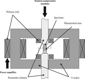
Figure 1. Magneto-mechanical characterization rig.
Download figure:
Standard image High-resolution imageThis setup has been optimized through a numerical analysis of magnetic and mechanical effects [26, 27]. Considering Terfenol-D and iron-cobalt alloy with a cross-section of about 100 mm2, this analysis ensures the uniformity of magnetic field and stress in a 15 mm height measurement area if the specimen is longer than 26 mm.
The samples characterized in this study are cylindrical Terfenol-D rods with 30 mm height and 5 mm radius. These polycrystals are as-grown rods produce by TdVib LLC using a directional solidification method and a heat treatment process. No processing has been further added to the samples. Measurements are performed at room temperature.
2.2. Characterization setup
The acquisition of measurement signals and the control of magnetic field and stress are performed by a DS 1006 dSPACE processor board, connected to a computer. The processor board ensures data acquisition, generation of excitation and controls signals through a DS2004 high speed A/D board (800 ns conversion time, 16 bit resolution) and a DS2103 D/A board (10 μs sample time, 14 bit resolution). Control of applied stress and position of the crosshead are ensured by the internal servo-controller of the compression machine. All the elements connected to the dSPACE acting during experiments are shown in figure 2. The magnetic field (H), the magnetic induction (B) and the strain components (S), are evaluated in the measurement area (figure 1).

Figure 2. Measurement setup schematic. Elements in bold are mechanical or electrical sources for the system.
Download figure:
Standard image High-resolution imageThe force (F) applied by the tension-compression machine (Zwick/Roell Z030) is measured using a 10 kN load cell (strain gauge sensor TC-LC010kN). Measurement resolution and accuracy of each sensor is 0.2 N ±0.06% in force, and 1 μm ±0.1% in displacement. Corresponding levels of measured noise (on dSPACE) are ±0.8 N and ±5 μm respectively.
A Kepco 72-14MG amplifier is used to produce current (I) in the four primary coils (figure 1). This power amplifier can generate 12 A and 70 V, with 0.2% accuracy. This current is measured using an LA 125-P current transducer. The accuracy of this probe is 0.6% and the measured noise is 4 mA. A Proportional-Integral-Derivative (PID) control loop feedback ensures an accurate and responsive generation of current. The accuracy of this control is very sensitive to the current stabilization of the power amplifier. The power amplifier shows a current offset of about 1–5 mA (depending on the temperature of the amplifier). This parameter is set in the control loop, and adjusted if necessary, to obtain a good control of low current levels.
The magnetic field (H) is measured using a GM08 Gaussmeter and a transverse Hall probe. This sensor can measure H from DC to 10 kHz with 1% accuracy. Using this probe with a range 0–230 kA m−1, the level of noise measured is 230 A m−1.
The variation of magnetic induction (δB) in the sample is calculated in real time through the integration of the induced voltage of a B-coil (65 turns) wound around the sample. Using a differential measurement of this voltage, the mean noise level is about 0.3 mV. Because this voltage is very sensitive to environmental conditions, it is evaluated before each measurement process and numerically reset. This way, a potential drift of δB is minimized and has been found to remain below 0.5 mT s−1. The level of measured noise is 0.1 mT. The reference state for the evaluation of B is the demagnetized state. The demagnetization process and the corresponding accuracy on the evaluation of B are discussed in appendix A.
The strain is measured through two strain gauge rosettes (rosettes 1 and 2) glued face to face on the surface of the sample in the measurement area. Each rosette consists in three gauges oriented at 0°, 45° and 90° from a reference axis. Using a 4-channel strain gauge conditioner (Vishay 2120B), two values in longitudinal direction (SL1 and SL2) and one value in the transverse direction (ST1) are evaluated. In addition, shear strain (SS1) is calculated using the gauge value in the 45° direction (S45°) in combination with SL1 and ST1 (SS1 = S45° – 0.5 × (SL1 + ST1)). Neglecting the effect of temperature variation, the accuracy of the gauges is about 0.5%. Measured noise for each strain measurement is about 1 × 10⁻⁶ strain. To minimize misalignment between the longitudinal direction of the sample and the column (and to avoid non uniform stress), a ball-and-socket joint (B&S joint) is placed between the load cell and the piezo stack actuator (see figure 2). This element can compensate ±3° (radius of 25 mm) for misalignment. Shear strain SS1 and the difference (ΔSL) between the two longitudinal strain measurements are calculated in real time during the experiment. Using the B&S joint, the position of the column is adjusted to minimize SS1 and ΔSL. Finally, for each level of pre-stress, the residual value of ΔSL at maximum field is evaluated, and an error of ΔSL/SL1 is considered to evaluate the error in the magnetostriction measurement.
The last point is the control of the dynamic force (ΔF) induced by the magnetic excitation, which is accomplished by the combination of a piezoelectric force sensor, a piezo stack actuator and a PID control loop feedback. The piezoelectric press force sensor (Kistler 9333A), linked to a charge amplifier (Kistler 5018), provides the dynamic component of the force, up to 50 kHz, with a 0.3% accuracy and a level of measured noise of ±0.05 N. The actuator is a preloaded high load actuator (modified P-235 HVPZT) with 80 μm travel range, equipped with a positioning system (strain gauge sensor) to provide position information (ΔL) to the piezo amplifier/controller. The piezo amplifier/controller is a high-performance piezo amplifier (E-481) with a 10 kHz sensor bandwidth signal conditioner (E-509). The system then ensures the cancellation of the dynamic force through the displacement provided by the actuator, controlled on the loop.
The dSPACE module stores and processes experimental data, produces desired excitation, prevents anomalous events (saturation of sensors or actuator, current or force limits), and controls the excitation signal and the dynamic force, at a sampling frequency of 50 kHz.
3. Magneto-mechanical characterization of Terfenol-D under controlled stress conditions (CSC)
The magneto-mechanical behavior of Terfenol-D under various compression stress levels has been characterized using this experimental setup. Hereafter, compression stresses will be considered positive. The lowest level of stress is obtained by positioning the Permendur column alone on the top of the sample. The weight of this element induces a compressive stress of 25 kPa on the sample. This configuration is considered as 'stress-free conditions' and the applied stress is assumed constant during the magnetic excitation. When connecting the top Permendur column to the compression machine (figure 2), pre-stress levels (σ0) of 125, 400, 700 kPa and 1, 2, 4, 8, 12, 16, 20, 25, 30, 35, 40, 45, 50, 55, 60, 70, 80, 90 MPa have been applied to the sample. For each level of stress, 10 major loops reaching ±100 kA m−1 (Hmax), are measured at 1 Hz frequency (quasi-static process). At this frequency, good current control is still achievable (dynamic error is on the order of the measured noise and the time delay is less than 1 ms).
Tests are done under CSC. The crosshead is set at a fixed position (controlled by the compression machine), and the stress control is ensured thanks to the piezo force sensor connected to the piezo actuator as described above. The reference state is the demagnetized state under pre-stress (mechanical loading applied before demagnetization). After a demagnetization process, all sensors are numerically reset to zero before starting the test.
Data presented in this work are raw data. No filtering has been performed at any stage. Error bars on each figure are calculated according to the error measurements described above.
3.1. Magnetization curves under CSC
Figure 3 shows the measured magnetization curves under constant compression stress. 10 loops are plotted for each pre-stress level.
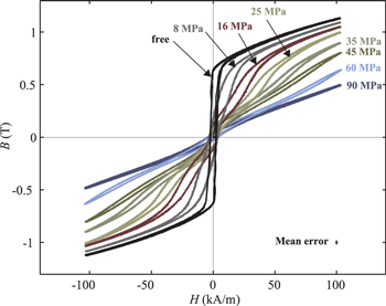
Figure 3. Magnetic behavior of a Terfenol-D specimen for various uniaxial applied compressive pre-stresses under controlled stress conditions. The error bar on the measurement of induction and magnetic field is reported at the bottom right side of the graph.
Download figure:
Standard image High-resolution imageIt is evident from figure 3 that a magnetic field of 100 kA m−1 is not sufficient to saturate the sample, particularly at high levels of applied stress. Under stress-free conditions, coercive field (Hc) is about 2.45 kA m−1, and magnetic induction for H = 100 kA m−1 (BHmax) is about 1.125 T. This is consistent with the values found in the literature [5, 8, 21, 26, 30, 33]. Magnetization curves are very sensitive to pre-stress levels. The decrease of induction with applied stress—for a given magnetic field—is expected but very significant. The width of the hysteresis curves is very connected to the applied mechanical stress.
In addition, these plots show that the drift of B can be neglected when applying 10 cycles. The repeatability of the measurement has been verified. The estimated error bar is reported at the bottom right side of figure 3.
3.2. Magnetostriction curves under CSC
Longitudinal and transverse magnetostriction curves are reported in figures 4 and 5 for levels of stress between the stress-free case and 16 MPa and between 16 and 90 MPa, respectively. 10 loops are plotted for each pre-stress level. The shape and level of longitudinal magnetostriction are consistent with results found in the literature [8, 26, 28, 33]. In the stress-free state, the shape and level of transverse strain are in good agreement with results obtained by Galopin et al [27]. Using the measured shear strain from the gauge, the misalignment between the gauge and the longitudinal direction of the sample has been estimated to be about 1.5°. This misalignment has been neglected in the following analysis. In addition, analytic formulation describing the level of strain induced by magnetic forces on the sample (form effect) has been computed (see appendix B). This study shows that the strain levels induced by form effect are negligible during these experiments.

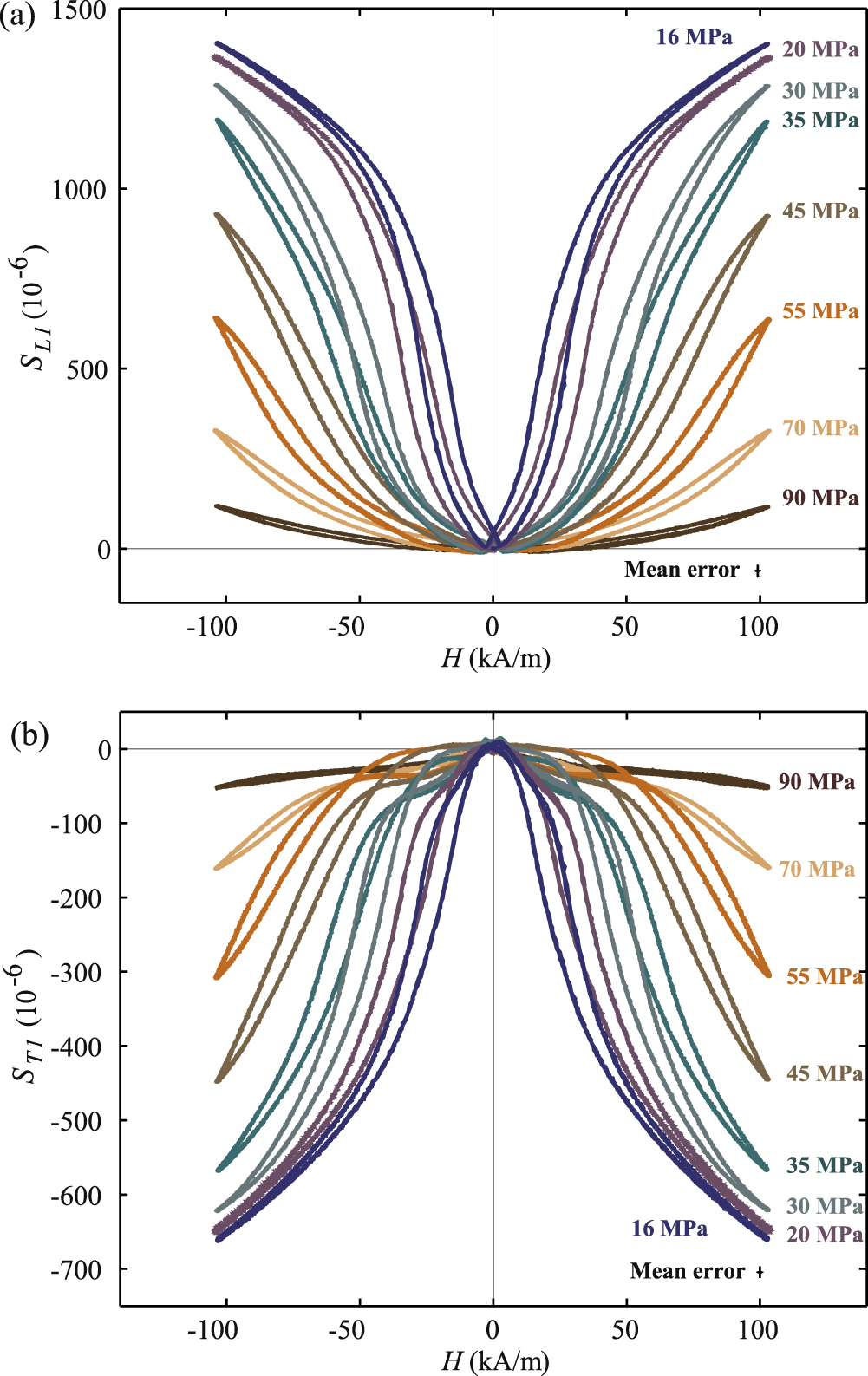
Figure 4. Longitudinal (a) and transverse (b) magnetostrictive behavior of a Terfenol-D specimen for various uniaxial applied compressive pre-stresses between 0 and 16 MPa under controlled stress conditions. The error bar on the measurement of strain and magnetic field is reported at the bottom right side of the graph.
Download figure:
Standard image High-resolution image
Figure 5. Longitudinal (a) and transverse (b) magnetostrictive behavior of a Terfenol-D specimen for various uniaxial applied compressive pre-stresses between 16 and 90 MPa under controlled stress conditions. The error bar on the measurement of strain and magnetic field is reported at the bottom right side of the graph.
Download figure:
Standard image High-resolution imageFigures 4 and 5 show that the magnetostrictive behavior is much more affected by stress than the magnetization behavior. The effect of stress on magnetostriction is not monotonic: at a given magnetic field, the application of a compressive stress can increase or decrease the magnetostriction level. The maximum variations of magnetostriction with respect to magnetic field are observed above 16 MPa. This is why GMM are usually used with an applied pre-stress, varying from a few MPa up to 50 MPa [1–6], in order to maximize the magnetostrictive response for a given applied field. Similar to the magnetization curves, the width of the magnetostrictive hysteresis is very dependent on the applied mechanical stress level.
Transverse magnetostriction is approximately half the longitudinal magnetostriction. This is consistent with the assumption of isochoric magnetostriction (no volume change). While observing the strain gauge measurement, and particularly shear strain, higher errors are found for magnetic fields below 40 kA m−1. However, shear strain always becomes negligible (less than 1% of longitudinal strain) above this level of magnetic field. These errors can be attributed to a residual misalignment in the setup. The application of stress naturally forces the setup into alignment, hence decreasing the error.
Figure 6 is another representation of the magnetostrictive behavior. It shows longitudinal and transverse magnetostriction curves with respect to magnetic induction. Contrary to what is sometimes assumed in the literature, it is evident from these curves that magnetostriction is not a quadratic function of the magnetic induction, and that the dependence to stress is very significant. It can also be noted that the hysteresis, which is very noticeable in the S(H) or B(H) representations, is less evident in the S(B) curves. This can be explained by the fact that magnetization (which is very similar to B) and magnetostriction are both images of the domain microstructure of the material, whatever the dissipation mechanisms, contrary to the S(H) or B(H) representations that incorporate information on domain wall motion and corresponding obstacles.

Figure 6. Longitudinal (a) and transverse (b) magnetostriction versus magnetic induction of a Terfenol-D specimen for various uniaxial applied compressive pre-stresses under controlled stress conditions. The error bar on the measurement of strain and magnetic induction is reported at the bottom right side of the graph.
Download figure:
Standard image High-resolution image4. Influence of the loading boundary conditions on the characterization of magneto-elastic behavior
This section is dedicated to the analysis of the role of boundary conditions, and their stability, on the characterization results. Results obtained under CSC are compared to those obtained for the same pre-stress levels under fixed cross-head conditions (noCSC). If we consider the extreme case of a perfectly rigid experimental setup, the dynamic stress (Δσ0) experienced by the sample would reach, in the case of Terfenol-D at Hmax, levels as high as 97.5 MPa (considering a maximum magnetostriction strain of 1.5 × 10⁻³ and an effective elastic modulus of 65 GPa (at Hmax) [34]). The results depend on the compliance of the experimental apparatus and are used here as an illustration of the critical role of boundary conditions in the characterization of magneto-mechanical behavior.
4.1. Control of loading conditions during magnetic excitation
Figure 7 plots the measured stress (using the load cell) with or without the piezoelectric actuator to maintain the stress constant during the tests. First, it is evident that the control system is able to maintain the stress constant during the tests, whatever the pre-stress level, within the limits indicated above. The fluctuations of stress under CSC do not exceed 0.1 MPa. In contrast, the cancellation of this control system (noCSC) results in very significant fluctuations of stress that can reach up to 11 MPa. These fluctuations are the direct image of magnetostriction since the setup elastically responds to the deformation of the sample. Fourier analysis of these signals shows that dynamic stress possesses frequency components up to 40 Hz (at low stress levels). Because the mechanical testing machine has a maximum testing frequency of 0.5 Hz, this signal cannot be efficiently controlled through the cross-head control electronics.
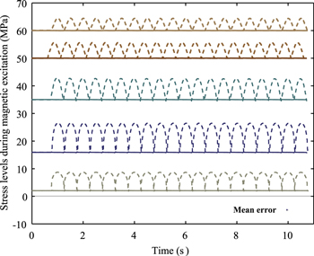
Figure 7. Stress levels experienced by the sample during magnetic excitation under 2, 16, 35, 50 and 60 MPa applied compressive stress: controlled stress conditions (plain line) and uncontrolled stress conditions (dashed line). The error bar on the measurement of stress is reported at the bottom right side of the graph.
Download figure:
Standard image High-resolution imageFigure 8 shows the level of maximum dynamic stress under static cross-head conditions (noCSC).
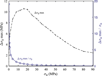
Figure 8. Maximum level of dynamic stress (dashed line) and associated ratio with the compressive stress level (plain line) during magnetic excitations under uncontrolled stress conditions. The error bars on the measurement of pre-stress and dynamic stress are reported for each level of pre-stress.
Download figure:
Standard image High-resolution imageAn accurate control of the stress level is particularly important in the region below 50 MPa which is precisely the usual operational range for this material. It can be noticed that Δσ0 reaches up to 20 times the magnitude of the applied stress at 0.4 MPa and it still represents 85% of σ0 at 12 MPa, which is unacceptable for an accurate characterization of the material behavior.
4.2. Sensitivity of magneto-elastic behavior to loading boundary conditions
The precise control of boundary conditions affects the measured magnetic behavior as can be seen in figures 9 and 10. Figure 9 shows the measured remanent induction (Br) and induction at maximum magnetic field (BHmax) as a function of the pre-stress level for a major loop with maximum field Hmax = 100 kA m−1. As expected from figure 3, an increase of the pre-stress significantly decreases the values of Br and BHmax. The values obtained under CSC conditions can be up to 20% higher for Br and up to 10% higher for BHmax compared to the values obtained under noCSC conditions.

Figure 9. Evolution of remanent induction (Br) and induction at Hmax = 100 kA m−1 magnetic field (BHmax) versus compressive stress levels under controlled stress conditions (CSC) and uncontrolled stress conditions (noCSC). The error bars on the measurement of stress and magnetic induction are reported for each level of pre-stress.
Download figure:
Standard image High-resolution image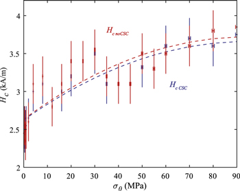
Figure 10. Evolution of Hc as a function of compressive stress under controlled stress conditions (CSC) and uncontrolled stress conditions (noCSC). The lines are just guides for the eye (polynomial regression, order 2). The error bars on the measurement of Hc and stress are reported for each level of compressive stress.
Download figure:
Standard image High-resolution imageFigure 10 shows the coercive field Hc as a function of the pre-stress. The evaluation of Hc is not very accurate due to the level of noise of the Hall probe used to evaluate the magnetic field. The noise is relatively large at low field and this results in large errorbars in figure 10. Regression curves (second order) of the measured points are given as a guide for the eye.
Figure 10 shows that the measurement of coercive field is relatively insensitive to the boundary conditions, CSC or noCSC, since the observed difference is within the errorbar. Moreover, it shows that the pre-stress tends to increase the coercive field from 2.45 kA m−1 in the stress-free state to 3.75 kA m−1 (CSC) under 90 MPa compression.
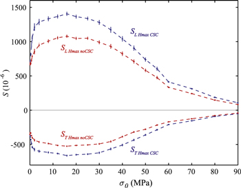
The role of boundary conditions is even more prominent for magnetostriction measurements, as illustrated in figure 11. The longitudinal and transverse magnetostriction strains, SLHmax and STHmax, obtained at Hmax = 100 kA m−1, are reported as a function of the pre-stress level. The values obtained under CSC are higher in amplitude than those under noCSC, which is expected since the stiffness of the setup tends to prevent the sample from elongating.
Figure 11. Evolutions of longitudinal and transverse magnetostriction strains at Hmax = 100 kA m−1 (SLHmax) and (STHmax) versus compressive stress levels under controlled stress conditions (CSC) and uncontrolled stress conditions (noCSC). The error bars on the measurement of stress and magnetostriction are reported for each level of pre-stress.
Download figure:
Standard image High-resolution image
As expected, the transverse strain amplitude is half the longitudinal one. The longitudinal and transverse strain measured under CSC can be up to 41% and 28% higher, respectively, than under noCSC.
5. Conclusions and perspectives
In this work, the design of an experimental setup dedicated to the characterization of GMM magneto-mechanical behavior under uniaxial constant pre-stress has been described. Measurements have been performed on a Terfenol-D sample to exhibit the dependence of magneto-mechanical behavior on compressive pre-stress levels from 0 to 90 MPa. Magnetization and magnetostriction (longitudinal and transverse) have been characterized under constant stress. It is shown that the experimental setup can control the stress induced by the magnetic excitation via magnetostriction and reduce it to levels below 0.1 MPa.
Measurements obtained under CSC have been compared to those obtained without using the stress control (noCSC). At low stress levels, the dynamic stress reaches 20 times the applied stress, and it still represents up to 85% the applied stress at 12 MPa. The evolution of magnetization is sensitive to the stress control conditions. The values obtained under CSC conditions can be up to 20% higher for the remanent magnetic induction Br and up to 10% higher for the magnetic induction BHmax at Hmax = 100 kA m−1 compared to the values obtained under noCSC conditions. Longitudinal and transverse magnetostrictive behavior has shown a greater sensitivity to the stress control conditions, with maximum differences about 40% and 30% respectively.
This work emphasizes the great importance of accurately controlling the boundary conditions in order to characterize the magneto-mechanical behavior of GMM such as Terfenol-D.
Appendix A.: Demagnetization process
Measurements provided by the B-coil give access to the variation of magnetic induction (δB). In order to evaluate B, this measurement has to be linked to the demagnetized state.
A demagnetization algorithm, inspired by [35], is used to demagnetize the material. First, a large sinusoidal current, with amplitude Isat, is applied to reach the positive and negative saturation states. An exponentially decaying sinusoidal current is then applied according to the following function

where f is the frequency and α is a damping parameter. This constant is defined as a function of the acceptable residual current (Ires) and of the number of cycles (N) to exponentially decrease from Isat to Ires

Under stress-free conditions, Ires has been chosen equal to the level of noise on the current (4 mA) and Isat has been set to 7 A, corresponding to a magnetic field close to 100 kA m−1 (Hmax). In other cases, Isat is chosen in order to maintain identical extremum values of the magnetic field (±Hmax) whatever the stress level.
When applying a major loop (±Hmax) just after the demagnetization process, the maximum magnetic induction (Bmax) and the residual magnetic induction (Bres) of the previous demagnetization process are evaluated, according to the extremum values of δB (noted δBHmax and δBHmax respectively)


The demagnetization process is considered successful if the following relation is verified

For the Terfenol-D samples of this study, it appears that 22 cycles are needed to exponentially decrease from Isat to Ires and to ensure a good demagnetization process.
According to equation (A.5), an error of 0.02∣Bmax∣ will be considered during the measurement of each B major loop.
Appendix B.: Analytic formulation and evaluation of form effect
Strains induced by surface and body forces of magnetic origin appear as a so called form effect superimposed on the pure magnetostriction mechanism [36]. The distributions of magnetic field and magnetic induction in the Terfenol-D sample create volume force density, described by the Maxwell stress tensor ( ). In an orthonormal coordinate system (n, t, n × t) in which B and H are vectors in plan (n, t), this tensor is expressed as
where μ is the magnetic permeability of the media, Bn the projection of B along n and Ht the projection of H along t.
In the setup configuration (figure 1), three surface forces have to be considered: the first two on the upper and lower surfaces in contact with the Permendur column ( ), which are symmetric, and the one on the free radial surface (
 ). These surface force densities can be computed from the jump of Maxwell stress tensor through normal direction of each sample surface [37]. By expressing them on the two surfaces, in cylindrical coordinate system (ur, uθ, uz)


where 
 and
and  correspond to the Maxwell stress tensor expressed in the Permendur column, in the Terfenol-D sample and in the air, respectively. Using classical magnetic boundary conditions on each surface, these tensors are expressed as a function of H in the Terfenol-D, which is considered to be uniform and along uz. This assumption allows us to express the magnetic field and induction in air and Permendur as a function of H


where μter, μper and μ0 are the magnetic permeability of the Terfenol-D, of the Permendur and of the vacuum respectively. It should be noted that μter and μper are functions of the magnetic field H in the Terfenol-D.
The stress tensor induced by form effect effect ( ) can then be expressed as
To evaluate the evolutions of  when varying the pre-stress, figure 3 has been used to approximate the evolution of μter as a function of H and for various pre-stress levels. Evolutions of μper as a function of H has been found in the literature [38]. The sensitivity of this parameter to the applied stress has been neglected. Under these approximations, for a magnetic excitation of 100 kA m−1,
  and
and  are maximum in the stress-free case, and never exceed 46 kPa (tension) and 52 kPa (compression) respectively. Using an effective elastic modulus (at 100 kA m−1) of 65 GPa [34] and a Poisson coefficient of 0.3, these stress levels correspond to strain values of 0.8 × 10⁻⁶ and 1.3 × 10⁻⁶ respectively. These levels of strain can then be neglected compared to the levels of magnetostriction (figures 4 and 5).