

Abstract
In this paper, a three-dimensional plasma jet model based on a hybrid algorithm was developed to study the sputtering phenomena during the interaction between the vacuum arc plasma jet and the anode. To improve the balance between accuracy and efficiency of the simulation model, heavy particles (ions and atoms) were treated as particles, while electrons were considered as a massless fluid. The Monte Carlo collision method was used to model inelastic collisions between heavy particles and electrons. In addition, the anode in this model did not only act as a passive current collector, but may also emit atoms into the gap when hit by heavy particles. The simulation results show that the anode is sputtered by the impact of high-speed ions from the plasma jet, and a stream of atoms is generated from the part of the anode surface that is in contact with the plasma. Some of the sputtered atoms are ionized into Cu1+ ions by colliding with electrons during their movement from the anode to the cathode. As a result of the production of these new ions, the Cu1+ ions density may exhibit a bimodal distribution with one peak near the cathode and the other near the anode. Furthermore, the ions can be divided into two groups according to their velocity distribution: high-speed ions moving from the cathode to the anode and low-speed ions moving in the opposite direction. These findings reveal that the sputtering process between the plasma and the material surface has a great influence on the energy distribution function of the ions in the plasma, which has often been ignored by researchers in previous studies.
Export citation and abstract BibTeX RIS
1. Introduction
Vacuum arc is a special type of electric discharge in a vacuum environment, which appears in various fields, such as ion sources, thrusters, coatings, and vacuum interrupters [1]. Unlike the gas arc, the plasma of the vacuum arc appears only as a result of erosion of the electrodes. During the vacuum discharge process, the luminous cathode spots on the cathode surface eject plasma jets into the interelectrode region to maintain the continuity of the current [2]. On the other hand, when the anode absorbs the plasma emitted from the cathode, secondary atomic sputtering will occur on the anode surface due to the impact of high-speed ions [3]. In addition, some areas of the anode will even melt and evaporate if the arc current is sufficiently high. These anode phenomena, which occur between the plasma and the anode, are complex, and, in some applications, they play a more important role than that of the cathode [4]. For example, severe anode melting can lead to excessive metal vapor in a vacuum breaker at current zero, resulting in an interruption failure [5]. Therefore, studying the interaction between the vacuum arc plasma and the anode is of great importance for the design and optimization of plasma-related applications.
In the past decades, numerous investigations have been conducted on anode phenomena in vacuum arcs. The anode temperature and erosion in high-current vacuum arcs were measured in references [6, 7]. The experiment results showed that a high anode temperature could lead to the appearance of anode spots and flowing liquid metal, which further generated significant quantities of plasma between the contacts. Janiszewski et al [8] observed the formation of anode spots and found that the jets emitted from these anode spots caused a deterioration of the current interruption capability. In reference [9], Batrakov et al concluded that the appearance of anode jets was related to the surface evaporation rate. Khakpour et al [10] combined the optical emission spectroscopy (OES) and high-speed cinematography methods and, consequently, observed that changes in anode modes could seriously affect the density of metal vapor and electrons. Wang et al [11] used optical absorption spectroscopy to measure the axial distribution of the chromium vapor density within the gap. They found that the maximum metal vapor density appeared near the electrodes during the arcing period.
The above experimental studies could provide only general results with limited insight in the underlying mechanisms regarding the anode effect. In order to gain a deeper understanding of the mechanism behind the interaction between vacuum arc plasma and anode, several numerical simulations have been performed. In 1982, Boxman and Goldsmith developed a zero-order model to investigate the anode region of the vacuum arc [12]. They found that the emission of neutral atoms from the anode surface could be caused by evaporation and sputtering, and all these atoms were eventually ionized by the electron impact. Schade and Shmelev built a high-current vacuum arc model using the magnetohydrodynamic (MHD) method; this model took into account the effect of anode evaporation [13]. Their simulation results showed that the anode vapor could alter the current density distribution and cause the vacuum arc to change from a diffuse pattern to a diffuse columnar pattern. Wang et al [14] established a heat conduction model to calculate the anode surface temperature and investigated the relationship between temperature and vacuum breakdown voltage through the particle-in-cell/Monte Carlo collision (PIC/MCC) method. Wang et al [15] used a two-dimensional (2D) MHD model to analyze the influence of the anode jet on the vacuum arc and highlighted the importance of the pressure balance between the anode jet and the cathode plasma.
Although the above studies have greatly improved our understanding of the interaction between plasma and anode in vacuum arc discharges, most simulations on the anode effect have focused on the influence of the anode evaporation on the plasma in the case of high-current vacuum arcs, while less attention has been devoted to the anodic sputtering effect. In the case of low-current or pulsed discharge, the increase in the anode surface temperature may not be pronounced because the energy injected into the anode is not large. Zabello et al [16] measured the spatial distribution of radiation intensity for different copper ionization states of low-current vacuum arcs. They believed that the anode was an important source of atoms and those atoms were rapidly ionized as they penetrate into the plasma. Zhou et al [17] pointed out that the anodic flare during vacuum arc breakdown was the result of anodic sputtering, which suggested that anodic sputtering had an important effect on the interaction between the anode and the plasma jet when the arc energy was small.
However, the simulation of the sputtering phenomenon between the plasma jet and the anode poses new challenges to the plasma simulation model. For the widely used MHD model, the absence of a kinetic description for the ions requires the introduction of velocity distribution assumptions to simulate the process of ions impacting the anode, which lacks accuracy. Regarding the PIC model, which is another powerful plasma simulation model, although the kinetic properties of microscopic particles are retained, this model is too computationally demanding. Thus, the PIC model is generally applicable only to physical problems with small spatial or temporal scales.
Recently, the hybrid plasma simulation model has become more widespread in many fields of plasma research [18–20]. This simulation approach does not require that all microscopic particles in the plasma must be treated in the same way. Instead, particles of different types or in different regions can be simulated as particles or fluids as required. By this means, the hybrid model can retain specific particle dynamics properties, while saving the computational resources needed for the simulation. P Sarraih et al used a one-dimensional (1D) hybrid model to calculate the dissipation process of residual plasma after current zero [21]. In reference [22], D L Shmelev investigated various modes of high-current vacuum arcs under different external magnetic fields by means of a 2D axisymmetric hybrid model. In our previous work [23], a three-dimensional (3D) hybrid plasma model was developed to study the continuous extinction process of a vacuum arc with multiple cathode spots from a high-current arc to complete quenching. The properties of the hybrid plasma model render this new approach to plasma simulation studies suitable for studying anodic sputtering in vacuum arcs.
In the present study, a 3D hybrid vacuum arc plasma jet model was developed to investigate in detail the sputtering phenomena between the vacuum arc plasma jet and the anode. In this model, heavy particles (atoms and ions) are treated as particles, while electrons are regarded as a fluid. The anode in this model does not only act as a current collector, but may emit atoms into the gap when hit by heavy particles. In addition, the MCC method was used to model inelastic collisions between electrons and heavy particles. The content of this paper is organized as follows. In section 2, the physical model of the plasma jet and the hybrid algorithm are introduced. Section 3 shows the main simulation results and the effect of several parameters on the anode sputtering process. In section 4, the influence of anode evaporation on the simulation results is discussed and the simulation results are compared with experiments. Finally, conclusions are presented in section 5.
2. Simulation model
2.1. Physical model
The physical model of the vacuum arc plasma jet is shown in figure 1; it is composed of a pair of parallel-plate copper electrodes and a plasma jet emitted from a cathode spot. It should be noted that the cathode spot in our model only works as a plasma jet emission source and not as a real cathode spot. As this work focuses only on the physical process of the interaction between the vacuum arc column and the anode, the detailed mechanism of plasma generation in the near-cathode region is ignored. However, for the convenience of description, it is still here referred to as the cathode spot. The anode may sputter under the impact of ions coming from the cathode, i.e. emitting copper atoms into the gap. Ionization and recombination collisions between electrons and heavy particles are considered in this model.
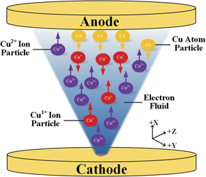
Figure 1. Physical model of the vacuum arc plasma jet.
Download figure:
Standard image High-resolution imageIn this model, both copper atoms and copper ions are simulated as particles, while electrons are regarded as a fluid. The basic idea of this treatment stems from the following fact: ions in a vacuum arc plasma jet have a supersonic drift velocity on the order of 104 m s−1, which is much greater than their thermal velocity. Thus, ions in the vacuum arc behave more like a beam for what concerns their transport [24]. On the other hand, the drift velocity of electrons is considerably smaller than their thermal velocity; thus, electrons behave more in a gas-type manner [25]. In this model, the arc current is 60 A, and the effect of its self-generated magnetic field is considered. The size of the computation domain is 10 × 20 × 20 mm3, and the cathode spot is set in the center of the yoz-plane. The grid lengths are set as Δx = Δy = Δz = 0.5 mm, and the time step is Δt = 1 × 10⁻¹⁰ s. As the collision process is considered in this model, the number of macroparticles in the simulation is particularly large, and a typical simulation result contains about 2.1 × 10⁶ macroparticles.
Several assumptions are adopted for the simulation:
- (a)The electrons are regarded as an ideal gas, i.e.

- (b)The plasma is assumed to be quasi-neutral, i.e.
- (c)The electron mass is ignored.
- (d)The effect of Joule heating and inelastic collisions on the electron energy is negligible because the current density and plasma density studied in this work are low. Therefore, the temperature of the electrons remains constant throughout the simulation, and this assumption is reasonably based on experimental results [26].
- (e)Excited atoms and ions are not considered in this model, and only direct ionization is taken into account in the collision process.


2.2. Hybrid model
The hybrid model for the vacuum arc plasma jet is governed by the following equations.
Heavy particles (ions and atoms) are treated kinetically using the PIC method:


where x i, v i, mi, and qi are the position, velocity, mass, and charge number of the copper ions and atoms, respectively. For the atoms, the charge number qi is 0. j is the current density of the plasma in the vacuum arc, and σ is the electrical conductivity. E and B represent the electric and magnetic fields, respectively. The last term in equation (4) represents the friction force between ions and electrons.
The electrical conductivity σ is expressed as:

where ne and me are the density and mass of the electrons, respectively. νei is the electron–ion collision frequency, and νea is the electron–atom collision frequency, which are written as:


where ln Λ is the Coulomb logarithm, and Zi is the mean charge number of the ions. na is the density of the atoms, and Te is the temperature of the electrons. σea is a constant equal to 10−19 m2 [27].
In the system of the multicomponent vacuum arc, the mean charge number value Zi is not uniform and is defined as:

The electron momentum equation is expressed as:
where
v
e is the electron velocity and Pe is the pressure of the electrons.  is the viscous stress tensor for the electrons.
The generalized Ohm's law is expressed as:

The current density of the plasma is the sum of the ion and electron current densities:

The current density is solved using Ampere's law, where the displacement current term is neglected:


where μ0 is the magnetic permeability in vacuum. According to Faraday's law, the evolution of the magnetic field is expressed as:

2.3. Boundary conditions
At the cathode side, the plasma parameters of the jet are derived from the calculation results of the near-cathode region simulations presented in reference [28]. The jet is fully ionized (only electrons, Cu1+ ions, and Cu2+ ions are contained), and it is emitted from the cathode spot in a cone with an angle of 60°. Additionally, the velocity of the ions is independent of the angle of departure. The initial charge state of the copper ions emitted from the cathode spot consists of 10% of Cu1+ and 90% of Cu2+. Thus, the mean charge value of the vacuum arc plasma jet is 1.9, which is consistent with the experimental results in reference [29]. Furthermore, the emission velocities of both ions are set to vi0 = 13 000 m s−1. The temperature of the electrons is 3.5 eV.
Only the cathode spot area emits plasma and current on the cathode side; all other areas on the cathode are inactive. The current density j0 and plasma density n0 at the cathode spot satisfy the following conditions:


where I0 = 60 A is the plasma jet current, and R = 1 mm is the effective radius of the cathode spot in this model. γ is the erosion rate of the copper electrodes, which is set to 35 μg C−1 according to the experimental data [30].
The anode in this model is not an ideal absorber. The impact of heavy particles (ion and atoms) on the anode can result in the sputtering of neutral particles. The sputtering model of Yamamura [31] is used to calculate the self-sputtering yield of copper, and the relationship between the incident particle energy and sputtering yield is shown in figure 2.

Figure 2. Energy dependence of the self-sputtering yield of Cu.
Download figure:
Standard image High-resolution imageThe initial position of the sputtered Cu atoms ejected from the anode surface is determined by the position of the particles hitting the anode surface. The initial velocity (va), axial angle (θ), and azimuthal angle (φ) of the sputtered atoms are calculated as follows [32]:


where U = 3.48 eV is the surface binding energy of copper [33], and r is a random number.
In addition, the effect of the anode sheath is taken into account at the anode, which accelerates the speed of the ions hitting the anode [34]. The anode sheath potential φsh is expressed as [35]:


where jex and jth are the axial electron current density and random electron current density, respectively. kB is the Boltzmann constant.
2.4. Ionization and recombination processes
In this work, the MCC method is used to model collisions between electrons and heavy particles (ions and atoms), i.e. heavy particles are collided with a target 'electron cloud'. Both ionization collisions and recombination collisions are included, where the dominant ionization mechanism is the electron impact, and the dominant recombination mechanism is the three-body recombination [36]. Within a time step Δt, the ionization probability (Pi) of an atom particle and the recombination probability (Pr) of an ion particle are expressed as follows [37]:


where IH = 13.6 eV is the ionization potential of the hydrogen atom. h is the Planck constant. Ig is the ionization potential of species g (I0 = 7.72 eV and I1 = 20.29 eV), which means that electrons need the energy of 7.72 eV for the Cu → Cu1+ reaction and the energy of 20.29 eV for the Cu1+ → Cu2+ reaction. The values of the ionization rate coefficient (α) and recombination rate coefficient (β) are shown in table 1 for an electron temperature of 3.5 eV.
Table 1. Values of the ionization rate coefficient and recombination rate coefficient.
| Te (eV) | α0 (Cu → Cu1+) | α1 (Cu1+ → Cu2+) | β0 (Cu1+ → Cu) | β1 (Cu2+ → Cu1+) |
|---|---|---|---|---|
| 3.5 | 2.88 × 10⁻¹⁴ | 8.11 × 10⁻¹⁷ | 6.62 × 10−42 | 6.76 × 10−43 |
3. Results
In section 3.1, typical results of the anode sputtering process are presented. Next, we systematically study the effect of several parameters on this process: the electron temperature (section 3.2), the plasma jet angle (section 3.3), the gap length (section 3.4), and the arc current (section 3.5). The parameters investigated and their values in each section are shown in table 2.
Table 2. Investigated parameters and their values in each section.
| Section | Electron temperature (eV) | Jet angle | Gap length (mm) | Arc current (A) |
|---|---|---|---|---|
| 3.1 | 3.5 | 60° | 10 | 60 |
| 3.2 | (2.5, 3.0, 3.5, 4.0) | 60° | 10 | 60 |
| 3.3 | 3.5 | (45°, 60°, 75°, 90°) | 10 | 60 |
| 3.4 | 3.5 | 60° | (5, 10, 15) | 60 |
| 3.5 | 3.5 | 60° | 10 | (30, 60, 90, 120) |
3.1. Anode sputtering process
Figure 3 shows the spatial distribution of the ion number density (Cu1+ and Cu2+) in the 3D space. The cathode and anode are placed at x = 0 mm and x = 10 mm, respectively. It can be seen that the ion number density decreases from the cathode to the anode. In general, the plasma jet is emitted from the cathode spot and then diffuses in a conical shape between the electrodes. Since only one jet is considered in this model, the plasma parameters have the same symmetrical distributions in the xoz-plane and xoy-plane; therefore, only the parameter distributions of the simulation results in the xoy-plane are shown below.

Figure 3. Ion number density in the 3D space.
Download figure:
Standard image High-resolution imageFigures 4 and 5 show the number density distributions of different species. From these figures, it can be inferred that different species have different density distributions in space due to their different production mechanisms. From figures 4(a) and (b), it can be seen that both ions (Cu1+ and Cu2+) are emitted from the cathode spot in a conical shape toward the anode. The shape of the jet is influenced by the plasma pressure as well as the velocity of the ions. Since the emitted ions all have highly supersonic drift velocities, their inertial force has a strong influence on the jet shape. In other words, the shape of the jet is influenced by the initial emission angle starting from the cathode spot. The overall number density of both ions gradually decreases from the cathode to the anode, which is different from that of the sputtered atoms. The maximum value of the number density for both ions is found at the cathode center, being 6.14 × 10¹⁹ m−3 for Cu1+ and 5.26 × 10²⁰ m−3 for Cu2+. Unlike the distribution of the number density of Cu2+, the density of Cu1+ firstly decreases and then increases along the central axis from the cathode to the anode. This is due to the influence of anodic sputtering on the plasma jet. The atoms sputtered from the anode produce new Cu1+ through ionization collisions with electrons, so a second peak in the Cu1+ number density occurs near the anode.

Figure 4. Number density distributions of different species: (a) Cu1+ ions and (b) Cu2+ ions.
Download figure:
Standard image High-resolution image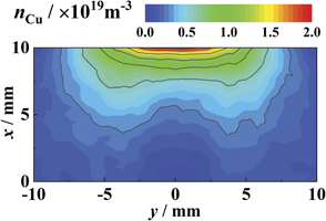
Figure 5. Number density distribution of the sputtered atoms.
Download figure:
Standard image High-resolution imageFigure 5 shows the number density distributions of sputtered atoms. It can be seen that the maximum value of the sputtered atomic density is found at the anode. The atoms sputtered from the anode move diffusely toward the cathode, and the number density of the atoms decreases gradually from the anode to the cathode. Near the anode, the maximum value of the atomic number density (∼1.98 × 10¹⁹ m−3) occurs along the central axis. This indicates that the sputtering phenomenon is most intense at the center of the anode directly opposite to the plasma jet. By contrast, near the cathode, the sputtered atomic number density exhibits a saddle-shaped distribution, and the maximum value does not occur along the central axis. During the movement of the sputtered atoms, the atoms and plasma jet interact with each other. Ionization collisions occur between atoms and electrons. As a result, the density of the sputtered atoms decreases rapidly in the region of the jet where the plasma density is high, resulting in a lower atomic number density in the jet region than in the region surrounding the jet.
Figure 6 shows the simulation results of the axial current density and self-generated azimuthal magnetic field of the plasma jet. In figure 6(a), the absolute value of the axial current density is shown, with the current direction pointing from the anode toward the cathode. Since the arc current is low (I0 = 60 A), the current is not constricted at the anode side. From the cathode to the anode, the axial current density decreases gradually with the increase of the jet cross section. In figure 6(b), the arc current self-generated azimuthal magnetic field is shown. Its direction is parallel to the electrodes, and its distribution corresponds to the conical distribution of the plasma jet. According to reference [38], the self-generated magnetic field inside the plasma restricts the radial expansion of the plasma flow, particularly for large currents. However, when the current is less than 200 A, its influence on the plasma shape and velocity is negligible. Therefore, in the model studied in this work, the plasma expansion is mainly influenced by the jet angle at the starting plane and the plasma density gradient force.

Figure 6. (a) Axial current density and (b) self-generated azimuthal magnetic field.
Download figure:
Standard image High-resolution imageFigure 7 shows the radially distributed anode potential drop calculated using Langmuir's formula (equation (21)) [39]. It can be seen that there is a negative potential drop (−2.52 V ∼ −5.31 V) in the anode sheath region and the absolute value of the potential drop in the anode center is the largest. Since the thermal velocity of electrons in a vacuum arc is usually much greater than the directional velocity of electrons, the negative potential drop in the anode sheath can repel most of the incident random electron flow to ensure the continuity of current [12]. In addition, the anode sheath can also regulate the energy of the ions injected into the anode [34]. Under the effect of the negative anode potential drop, ions are accelerated as they pass through the anode sheath. According to the relationship between the sputter yield and the incident ion energy (shown in figure 2), the larger energy of the incident ions corresponds to larger sputter yields. Therefore, the anode potential drop enhances the anode sputtering phenomenon.

Figure 7. Anode potential drop distribution along with the radial distribution.
Download figure:
Standard image High-resolution imageIn figure 8, the phase space distribution diagrams of different types of particles are shown, where vx > 0 indicates that the particle movement is from the cathode to the anode, while vx < 0 indicates the opposite. For the sputtered Cu atoms, it can be seen that their direction of movement is from the anode to the cathode. In addition, since the sputtered atoms have a random speed direction, these atoms are distributed throughout the gap between the electrodes. In figure 8(b), it can be observed that two groups of Cu1+ ions are located in the gap of the vacuum arc: a large number of high-speed ions moving from the cathode to the anode and a small number of low-speed ions moving in the opposite direction. Among these, the high-speed Cu1+ ions are emitted from the cathode spot, while the low-speed Cu1+ ions are sputtered atoms ionized by electrons. In figure 8(c), it can be seen that the Cu2+ ions are almost all high-speed ions emitted from the cathode spots, and they are mainly distributed in the jet channel.
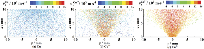
Figure 8. Phase space distribution diagrams of different particle species.
Download figure:
Standard image High-resolution imageIn figure 9, the probability density functions of the velocity along the x-direction for different species are shown, where vx > 0 indicates that the particle movement is from the cathode to the anode, while vx < 0 indicates the opposite. As can be seen from figure 9, all sputtered Cu atoms move from the anode to the cathode, while Cu1+ ions contain both low-speed ions moving from the anode to the cathode and high-speed ions moving in the opposite direction, with a greater proportion of high-speed ions. All Cu2+ ions move from the cathode to the anode. In addition, it can be observed that, although the low-speed ions are ionized from the sputtered atoms, their mean velocity is smaller than that of the atoms, which indicates that the low-speed ions are slowed down during their movement from the anode to the cathode. Additionally, comparing the velocity distributions of the Cu1+ ions and Cu2+ ions, it can be found that, although they have the same velocity when they are emitted from the cathode spot, the mean velocity of the Cu2+ ions in the vacuum arc is larger than that of the Cu1+ ions. The above results indicate that, while moving from the cathode to the anode, the ions are accelerated by the plasma pressure gradient, the frictional force between the electrons and ions, and other factors. Furthermore, the larger the ion charge, the stronger the acceleration effect.
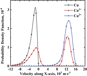
Figure 9. Probability density functions of the velocity along the x-direction for different particle species.
Download figure:
Standard image High-resolution imageFigure 10 shows the density distribution of the Cu1+ ions ionized from the sputtered Cu atoms; it can be seen that the new Cu1+ ions are mainly distributed inside the plasma jet channel. The Cu atoms sputtered from the anode are uniformly diffused, and the ionization collisions occur mostly in the jet channel due to the high electron density inside the jet channel. As can be seen from table 1, α0 is much larger than α1, indicating that the ionization of Cu atoms into Cu1+ ions occurs more readily in the case of electron collisions. In the simulation conditions adopted in this study, almost no new Cu2+ ions are produced by ionized collisions.
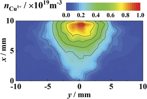
Figure 10. Density distribution of the Cu1+ ions ionized from the sputtered Cu atoms.
Download figure:
Standard image High-resolution imageFigures 11(a) and (b) show the Cu1+ molar fraction in the Cu ions and the mean charge value of the ions, respectively. As only two different types of ions are considered in this model, the molar fraction of Cu2+ ions is calculated by subtracting the molar fraction of Cu1+ ions from one. The maximum molar fraction of the Cu1+ ions occurs outside the jet channel. It can be seen from figure 8 that the Cu2+ ions are mainly distributed inside the jet channel, while some Cu1+ ions appear around the jet channel because they are ionized from the sputtered atoms. Within the plasma jet, the molar fraction of Cu1+ ions gradually increases from the cathode to the anode as the sputtered Cu atoms are gradually ionized during the penetration of the plasma. On the cathode side, the molar fraction of Cu2+ ions reaches its maximum, which leads to the maximum mean charge value near the cathode. Additionally, on the cathode side, the mean charge value is reduced due to the ionization of the sputtered atoms.

Figure 11. (a) Molar fraction of Cu1+ in Cu ions and (b) mean charge value of the ions.
Download figure:
Standard image High-resolution image3.2. Effect of the electron temperature
To study the effect of the electron temperature on the sputtering process, we have performed simulations with the electron temperatures of 2.5 eV, 3.0 eV, 3.5 eV, and 4.0 eV. Figure 12 shows the probability density functions of the velocity of Cu1+ along the x-direction with different electron temperatures. It can be seen that velocity distributions of Cu1+ ions along the x-direction are bimodal in all cases. The Cu1+ ions between the electrodes all contain two ion groups: low-speed ions moving from the anode to the cathode and high-speed ions moving in the opposite direction. As shown in figure 8, these two ion groups have different production mechanisms, resulting in different velocity distributions. Low-speed ions are generated by electron ionization during the interaction between sputtered atoms and the primary plasma jet, while high-speed ions come from the cathode spot. The main influence of electron temperature on the sputtering process lies in the ratio of low-speed ions to high-speed ions. As expected, a higher electron temperature will cause more sputtered atoms to be ionized.
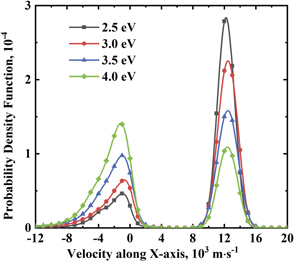
Figure 12. Probability density functions of the velocity of Cu1+ along the x-direction with different electron temperatures.
Download figure:
Standard image High-resolution image3.3. Effect of the jet angle
The angle of the plasma jet can affect the anode sputtering process in two ways. The first is about the geometry of the plasma jet. A larger jet angle results in a larger contact area between the plasma jet and the anode when the distance between the electrodes is constant. The second effect is that a larger jet angle decreases the plasma density of the jet, in particular in regions close to the area. For the anode sputtering process, these two factors determine the energy density of the ions that hit the anode and the density of electrons that interact with the sputtered atoms. To investigate how the plasma jet angle affects the sputtered atoms, we have performed simulations with the jet angles of 45°, 60°, 75°, and 90°. Figure 13 shows the number density distributions of the sputtered atoms with different plasma jet angles. The maximum sputtered atom density in the anode center occurs when the jet angle is smallest and the sputtering area of the anode is large with increasing jet angle. Note that the distribution of sputtered atoms is influenced by the primary jet and has a saddle shape, which is most clearly visible for the angle of 45°. This is because when the jet angle is smaller, the plasma density of the jet is higher, resulting in a larger portion of the sputtered atoms being ionized.

Figure 13. Number density distributions of the sputtered atoms with different plasma jet angles.
Download figure:
Standard image High-resolution image3.4. Effect of the gap length
In the ion source, the vacuum arc plasma jet may operate under different gap lengths. To study how gap length affects the anode sputtering process, we have performed simulations with gap lengths of 5 mm, 10 mm, and 15 mm. As before, the electron temperature was 3.5 eV, the arc current was 60 A and the jet angel was 60°. The number density distributions of different species with different gap lengths are shown in figure 14. With the increase in the gap length, the contact surface between the plasma jet and the anode keeps growing, but the density of sputtered atoms near the anode becomes smaller and smaller. The plasma jet is emitted from the cathode spot and then diffuses into the interelectrode region, and the plasma density inside the jet becomes smaller as it gets further away from the cathode. According to equation (24), the ionization probability Pi of sputtered atoms is related to the electron density. The higher the electron density, the more likely the sputtered atoms are ionized into ions. Therefore, it can be seen from figure 14 that a larger part of the sputtered atoms are ionized when the gap length is reduced.
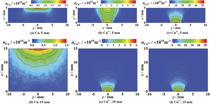
Figure 14. Number density distributions of different species with different gap lengths.
Download figure:
Standard image High-resolution image3.5. Effect of the arc current
In this section, the influence of the arc currents on anodic sputtering is investigated. Simulations for currents of 30, 60, 90, and 120 A were performed. In each simulation, the number of emitted ions and the current density at the cathode are changed accordingly to the arc current, while both the ratio of the two ions and the velocity of the ions remain constant. Beilis and Keidar calculated the electron temperature distribution as a function of arc currents [40]. They found that, when the arc current is less than 1000 A, the influence of the current on the electron temperature is rather moderate. Therefore, for our simulations under different arc current conditions, the electron temperature was considered to remain constant.
Figure 15 shows the number density distributions of different species for arc currents of 30 and 120 A. Comparing figure 15(a) with figure 15(d), it can be observed that the maximum number density of sputtered atoms becomes larger as the jet current increases. This is due to the fact that the increased arc current causes more high-speed ions moving from the cathode to hit the anode, thus causing a more intense anode sputtering phenomenon. In addition, when the arc current is 30 A, the sputtered atoms are hardly ionized and spread from the anode to the cathode, while, when the arc current is 120 A, the sputtered atoms inside the plasma jet are almost completely ionized in the immediate vicinity of the anode surface.

Figure 15. Number density distributions of different species for arc currents of 30 and 120 A: (a) 30 A, Cu; (b) 30 A, Cu1+; (c) 30 A, Cu2+; (d) 120 A, Cu; (e) 120 A, Cu1+; (f) 120 A, Cu2+.
Download figure:
Standard image High-resolution imageSince a large proportion of the sputtered atoms are ionized when the arc current is 120 A, it can be observed from figure 15(e) that the Cu1+ ions density exhibits a bimodal distribution, with one peak near the cathode spot and the other peak near the anode. Figure 16 shows the probability density distributions of the velocity of the Cu1+ ions along the x-direction under different jet currents. It can be seen that, as the arc current increases, the proportion of low-speed ions becomes increasingly larger, which indicates that more sputtered atoms are ionized.
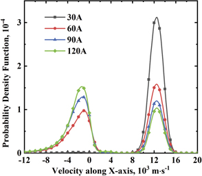
Figure 16. Probability density functions of the velocity of Cu1+ ions along the x-direction under different currents.
Download figure:
Standard image High-resolution imageThe influence of the change in arc currents on the ionization degree of the sputtered atoms is analyzed in the following. As indicated above, the electron temperature in the vacuum arc is Te = 3.5 eV and the electron concentration is ne ≈ 1019–1020 m−3. In plasmas with such parameters, the ionization time of the Cu atoms is expressed as:

where σi is the cross section of the ionization caused by the electron impact. The ionization free length of the sputtered atoms can be estimated as:

where va is the velocity of the atoms. Their average velocity can be obtained from figure 9 as va ≈ 2500 m s−1. Therefore, when the density of the plasma jet increases with the current, the sputtered atoms are more likely to ionize under the influence of the plasma jet. From figures 15 and 16, it can be observed that the number of sputtered atoms being ionized becomes larger, and the proportion of low-speed ions increases.
4. Discussion
4.1. Influence of evaporation
In addition to causing sputtering phenomena, the jet heats the anode causing evaporation from the anode surface. In this section, the influence of evaporation from the anode surface on the atomic density is investigated. A 1D heat diffusion model of the anode is developed using the COMSOL software. In this model, the energy deposited by the plasma jet, the energy lost through evaporation, and the energy transfer caused by heat conduction are considered, while the phase transfer and deformation on the anode surface are neglected. The thermal conduction inside the anode can be written as:

where ρ is the density of the contact material, CP is the heat capacity, T is the temperature, and λ is the heat conductivity.
The boundary conditions are defined as the anode surface and the non-anode surface. The non-anode surface is considered adiabatic. According to Fourier's law, the boundary condition of the anode surface is expressed as follows:

where Qin and Qev denote the energy density injected into the anode by the plasma jet and evaporated from the anode surface, respectively. The energy injected into the anode by the plasma jet is obtained by calculating the sum of the energies of the electrons and ions entering the anode in the hybrid jet model above. The energy flux taken away from the anode surface by evaporation can be expressed as:

where L is the latent heat of evaporation, NA is the Avogadro constant, and ϕ is the rate of evaporation:

where m is the atom mass, and Psat is the saturated vapor pressure. The latter can be calculated using the Clausius–Clapeyron equation as follows:

where Patm is the atmospheric pressure, R is the gas constant, and Tb is the boiling temperature of the material.
The length of the calculation domain is set to 2 cm, which is consistent with the thickness of the commonly used anode contacts. The energy density injected into the anode (Qin) is considered to be a constant during the simulation; i.e. the jet maintains its energy unchanged to continuously heat the anode. The value of Qin = 3.26 × 10⁷ W m−2 is obtained from the simulation results of section 3.1. The parameters used in the simulation are shown in table 3. Taking the initial temperature of the anode as 300 K, the heat diffusion equation is solved using the COMSOL software.
Table 3. Physical parameters of copper.
| Material | P (kg m−3) | CP (J kg−1 K−1) | Λ (W m−1 K−1) | Tm (K) | L (kJ mol−1) | Tb (K) |
|---|---|---|---|---|---|---|
| Cu | 8930 | 386 | 397 | 1356 | 304.8 | 2833 |
After obtaining the anode surface temperature, the atomic density of evaporation from the anode surface can be calculated using the ideal gas law: nev = Psat/kT. The temperature of the anode surface and the corresponding number density of the evaporated atoms as a function of time are plotted in figure 17. It can be seen that the temperature of the anode surface rises very slowly. Even if the plasma jet continues to heat the anode for 1 s, the evaporation from the anode surface (2.11 × 10¹⁸ m−3) fails to provide a number of atoms comparable to that obtained from sputtering (1.98 × 10¹⁹ m−3). Therefore, the anode evaporation caused by the plasma jet makes no sizeable contribution to the plasma concentration when the arc current is small.

Figure 17. Temperature of the anode surface and corresponding number density of the evaporated atoms.
Download figure:
Standard image High-resolution imageThis simple estimation shows that the influence of evaporation from the anode surface is negligible in our simulations. The authors of references [12, 16] came to a similar conclusion for a small arc current, as they found that the cathode was only eroded in vacuum arcs with currents up to several hundred amperes. However, in the case of the evaporated atom density growing exponentially with rising temperature, it is plausible to expect that the evaporation from the anode may play a significant role when the arc current is high.
4.2. Comparisons with experiments
The OES technology is a very important experimental method for researches on vacuum arcs [41]. As a non-invasive plasma diagnostic method, it can provide information about the spatial distribution of various microscopic particles in the vacuum arc [16, 42–44]. To further verify our simulation results, we conducted a spectroscopic analysis of the plasma jet during the discharge.
The schematic of the experimental system is shown in figure 18. It consists of a vacuum chamber (∼10−3 Pa), a DC circuit (60 A), and an optical diagnostic platform. In addition, the optical diagnostic platform used here is similar to the experimental setup in our previous paper [45]. The CCD camera and the spectrometer (with an ICCD camera) were used to record images and spectral information of the plasma jet, respectively. To make the plasma jet more likely to appear in the slit observation area of the spectrometer, a special wedge-shaped Cu cathode (as shown in figure 18) and a flat Cu anode were used in the experiment. When the cathode spot burns on the top of the cathode, the ICCD camera mounted on the spectrometer can capture the spectral information of the plasma jet on the axis. In addition, a CCD camera opposite the spectrometer was used to record the entire process of the vacuum arc discharge to observe whether the plasma jet was emitted from the top of the cathode during the ICCD operation. The diameter of both electrodes was 20 mm and the gap length was 10 mm. Besides, the discharge was ignited by triggering a spark on the edge of the cathode surface.
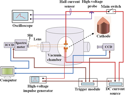
Figure 18. Schematic diagram of the experimental setup.
Download figure:
Standard image High-resolution imageThe comparison between the experimental spectrum results and the simulation results is shown in figure 19. The solid line represents the relative value of the spectral intensity distribution of Cu1+ on the axis. The spectral line of Cu1+ ions at 505.2 nm was chosen to present in the results because it was easily distinguished from other spectral lines and its signal-to-noise ratio was high in our experiments. Due to the continuity of the light radiation, spectral signals were also be detected below the cathode and above the anode. Moreover, it can be seen that the intensity of the spectrum is strongest at the cathode, then gradually decreases from the cathode to the anode, and increases again near the anode. Further, since the spectral intensity is considered to be proportional to the concentration of the corresponding microscopic particle [41, 43], the trend of the spectral intensity is to some extent the trend of the particle density. The scattered points indicate the relative value of Cu1+ density distribution calculated from the simulation, and the simulation conditions are the same as in section 3.1. Comparing the experimental and simulation results, it can be found that they share the same distribution characteristics, although they are not completely consistent. Additionally, similar results were also observed in some previous experiments [16, 42, 46].

Figure 19. The solid line represents the relative value of the spectral intensity distribution of Cu1+ on the axis (Cu II 505.2 nm), and the scattered points represent the relative value of Cu1+ density distribution.
Download figure:
Standard image High-resolution image
5. Conclusions
In this work, the sputtering phenomena during the interaction between the vacuum arc plasma jet and the anode was investigated with numerical simulations. A 3D vacuum arc jet model based on the hybrid plasma algorithm was developed, in which atoms and ions were treated as particles, while electrons were regarded as a fluid. The model included an MCC procedure for describing the inelastic collisions between electrons and heavy particles. The main findings of this study are summarized as follows:
- (a)The anode is sputtered by the impact of high-speed ions from the vacuum arc plasma jet, and a flow of atoms is generated from the region of the anode surface that is in contact with the arc. The sputtered atoms diffuse from the anode toward the cathode, and their density gradually decreases.
- (b)Both smaller jet angles and shorter gap lengths lead to an increase in the density of the plasma in contact with the anode, which in turn intensifies the sputtering phenomenon at the anode.
- (c)Some of the sputtered atoms are ionized into Cu1+ ions by colliding with electrons during their movement from the anode to the cathode, and these newly ionized ions are mainly distributed within the plasma jet. As a result of the generation of these new ions, the Cu1+ ion density may exhibit a bimodal distribution with one peak near the cathode spot and the other near the anode.
- (d)The velocity of the atoms sputtered from the anode is much lower than the velocity of the ions emitted from the cathode spot. When some of the sputtered atoms are ionized, the ions between the electrodes contain both low-speed ions moving from the anode to the cathode and high-speed ions moving in the opposite direction. Furthermore, both higher electron temperatures and larger arc currents lead to an increased proportion of sputtered atoms being ionized during their movement.
Acknowledgments
This work was supported by the National Natural Science Foundation of China under projects No. 51937009 and 51807147.
Data availability statement
All data that support the findings of this study are included within the article (and any supplementary files).