

Abstract
The effect of background neutral density on the ion acceleration region of a magnetic nozzle thruster is investigated through a combination of theoretical models and experiment. Ion velocities are measured in the magnetic nozzle using laser induced fluorescence as the background pressure is raised from 0.98 to 26 μTorr-Xe. It is found that the ion velocity exiting the acceleration region decreases from roughly 12 800 to 10 200 m s−1 as background pressure is increased corresponding to a drop in accelerated ion energy of 37%. Global models are employed to determine discharge properties and to calculate the power consumed by collisions in the plume. It is found that charge exchange collisions in the plume cannot explain the decrease in performance. As an alternative, inelastic electron–neutral collisions in the plume are proposed as the mechanism responsible for the decrease in ion energy, consuming between 1.6% and 39% of the power incident on the plume as background pressure is increased over the range tested. The findings suggest that facility effects can significantly alter plume dynamics and thruster performance even at relatively low background pressures. However, with the validated global models it is possible to make predictions of on orbit ion velocities using data taken at finite background pressures.
Export citation and abstract BibTeX RIS
1. Introduction
Magnetic nozzle thrusters are an electrodeless form of electric propulsion (EP) that offer several potential advantages over state-of-the-art technologies [1, 2]. They in principle can have longer lifetimes as they do not require the types of plasma wetted electrodes that often are the life limiting components of conventional EP systems. Primarily, they do not require a neutralizer cathode, which is a known failure source on many EP devices. Furthermore, these devices can be more resilient (though not impervious) to plasma surface interactions, enabling the use of more exotic or storable propellants like metal and water. Proposed magnetic nozzle thruster concepts range in power from tens of watts to hundreds of kilowatts, making them a viable technology for both large-scale interplanetary missions and nano-satellites [3–5]. The increasing demand for propulsion in small spacecraft missions in the past decade has led to a particular emphasis on magnetic nozzle development at lower powers.
Magnetic nozzles rely on a shaped magnetic field to turn randomized thermal energy into directed kinetic flow. This conversion is a complex process that varies with different magnetic nozzle designs [6]. For the low power designs that are actively being explored for small satellite propulsion, power is absorbed primarily by plasma electrons. These heated electrons are expelled through the magnetic nozzle setting up an ambipolar field that accelerates ions from the plasma source. This acceleration process has been experimentally shown to take place over a distance greater than several thruster radii [7]. Because ion acceleration occurs beyond the exit plane of the plasma source, these thrusters can be designed to be very resilient to erosion from ion impact. However, this effect also leads to the acceleration region being several times the volume of the thruster and thus makes these devices more susceptible to so-called facility effects. The possibility of EP thrusters interacting with the facility environment is a widely recognized problem in the field as it calls into the question our ability to extrapolate the measured performance of these systems to their intended environment in space [8].
While facility effects continue to be an on-going area of research for most forms of EP, magnetic nozzles pose a particular challenge: experimental efforts have revealed their response to facility effects–particularly the presence of excess neutrals due to finite pumping speed–is different from other state-of-the-art EP technologies. For example, as experiments by Vialis et al using a magnetic nozzle with an electron cyclotron resonance (ECR) source operating at 40 W have shown, efficiency can decrease by more than a factor of two (9%–3.9%) as pressure is doubled (5.4–9.75 μTorr) [9]. Using Faraday probe measurements, Vialis found that the divergence of plasma within the plume increased and on-axis ion current density decreased by almost 75% as background pressure was raised. Studies of magnetic nozzles employing a helicon plasma source that were conducted at higher facility pressures (14–66 μTorr, 100 W) revealed similar trends [10]. In both cases, the changes in efficiency and divergence were actually counter to what is found for more mature forms of EP such as Hall thrusters. These latter technologies typically improve in performance with increasing pressure [11–13]. The types of arguments that have been employed for these systems to explain facility effects thus do not seem to apply to magnetic nozzles.
There have been a number of theories to date to explain the unique response of magnetic nozzles to finite pumping speed. These have included background neutral ingestion impacting the energy balance in the upstream source region where the plasma is formed [10], as well as energy losses due to the onset of secondary discharges occurring outside the thruster plume when the neutral environment is sufficiently high [14]. Recent works by Vialis [9] and Collard and Jorns [15] have shown that the presence of excess neutrals also can directly impact the dynamics of the magnetic nozzle itself, i.e. the ability to convert thermal energy into directed kinetic energy. These works have demonstrated, for example, that the acceleration profile of ions is correlated with the presence of neutrals and that changes in performance can be explained almost entirely by these shifts in the acceleration. This suggests that neutral collisions in the plume may in fact be the dominant driver for many of the pressure-related facility effects in low-power devices. With that said, despite the existing correlation and phenomenological evidence, it has not been established causally why the presence of neutrals could yield these types of changes in the acceleration region. The goal of this study is to develop and validate a first-principles model linking the ion dynamics in the nozzle plume to excess neutrals resulting from facility effects.
To this end, this paper is organized in the following way. In section 2, we relate ion acceleration to both the power entering a magnetic nozzle (in the form of ion kinetic energy and electron pressure) and the power consumed by plume collisions. We then present global models of the thruster's main discharge and plume regions to predict these values. In section 3, we give an overview of an experimental setup including the test article and diagnostics. Section 4 details the measured neutral pressures, power coupling data, and ion velocity distribution functions (IVDFs), and gives the results of the predicted power consumed by collisions within the plume. Finally, we discuss the overall impact of neutral collisions on ion acceleration within the plume and perform a sensitivity analysis of our model. We use these results to predict ion velocities for a range of neutral pressures including space-like environments.
2. Theory
The governing hypothesis of this work is that changes in nozzle performance with increasing facility pressure can be explained by the unrecoverable loss of ion and electron energy that results from collisions with the background gas. This process acts as an energy sink that curtails the ability of the nozzle to effectively convert thermal energy introduced in the source into directed kinetic energy for thrust at the exit. We represent this loss explicitly by defining a power balance for the plume region of the thruster under the assumption of ambipolarity at the nozzle throat and exit, as well as quasi-1D expansion along the diverging magnetic field:
Here we have defined Pt as the power entering the plume at the nozzle's throat, and we have denoted the power that leaves the nozzle geometry at the exit as the combination of ion kinetic energy,  , electron heat flux
  , and the flux of thermal energy,
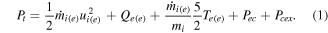
  . In these expressions, mi denotes ion mass, ui denotes ion speed, and the subscripts refer to the (e) exit and (t) throat regions shown in figure 1. We also have introduced two terms that represent the power lost by interspecies collisions: Pec, the power consumed by electron–neutral ionization and excitation collisions and Pcex, the power absorbed by charge exchange (CEX) collisions between ions and neutrals within the plume.

Figure 1. Notional cross-section for the magnetic nozzle thruster showing key features of the discharge including the throat (t), thruster radius (rT), vacuum interface lines (rVL), acceleration length, and nozzle exit (e).
Download figure:
Standard image High-resolution imageThe balance in equation (1) shows quantitatively that the kinetic energy of the flow (which is the component that contributes to thrust) can be decreased in two ways. The first is that there is residual thermal energy in the flow as it exits the nozzle. This is a consequence of imperfect nozzle expansion and can be represented as a nozzle conversion efficiency (see [15] for more on this topic). The second loss—and the one which is the focus of this investigation—is the power that is absorbed by interspecies collisions that is not recovered. Using this model, we in principle can directly relate the power consumed within the plume by these collisions to a reduction in final ion velocities. Estimating the quantities involved in this expression explicitly, however, requires a detailed description of the plasma properties in the primary discharge and plume regions. In the following, we motivate simple 0D and quasi-1D models for each of these contributions.
2.1. Plume energy loss model
In this section, we present models for the loss terms in equation (1): Pcex, which stems from ion-neutral collisions and Pec, which stems from electron–neutral collisions.
2.1.1. Ion-neutral collisions in the plume
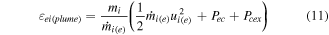
Both CEX and elastic ion-neutral collisions can occur in the plume of the magnetic nozzle. We only consider the former, however, as they are a more dominant contributor in influencing changes in ion momentum and energy in the plume [16]. To this end, we quantify the power consumed by CEX collisions in the plume volume, Vplume, starting with the relation

where ni is the ion number density, ui is the accelerated ion velocity, which we assume to be monoenergetic, and  is the CEX collision rate given by
  . Here, ng is the neutral gas density and
  is the cross section for CEX collisions in xenon given as a function of ion energy by an empirical approximation in [17].
In order to simplify this integral, we again invoke a quasi-1D approximation for the expanding nozzle flow such that  . This allows us to write equation (2) as

For this expression, in addition to the quasi-1D approximation, we have assumed stationary neutrals and approximated the ion mass flow,  , as constant throughout the plume. We similarly have introduced an effective length, L, that bounds the plume region. This length (labeled acceleration length in figure 1) corresponds to the point where the nozzle induced acceleration of the ions is complete and is commonly referred to as the detachment point. The location of this point is not fully understood and cannot easily be calculated. Using experimental measurements of ion velocity, however, we can estimate this length as the point where ion acceleration ceases [15]. Each CEX collision in this expression consumes 100% of the incoming ion's kinetic energy. We can therefore neglect collisions between secondary ions and neutrals. We note here that this analysis gives an upper bound on Pcex as in practice
  for primary ions will decrease with each CEX collision.
2.1.2. Electron–neutral collisions in the plume
We calculate the power consumption from electron–neutral collisions in the plume in terms of the energy consumed by ionization, excitation, and elastic collisions:

where  denotes the local neutral gas density, ne is the local electron density, Kiz is the ionization rate constant, Kex is the excitation rate constant, and Kel is the elastic collision rate constant. Similarly, we have introduced
  as the first ionization energy, 12.13 eV for xenon,
  is the average excitation energy, 8.32 eV for xenon, and
  is the average energy consumed by elastic collisions [18].
Evaluating these expressions for electron–neutral power consumption requires that the electron temperature, neutral density, and plasma density all be known within the plume region. Additionally, an effective plume volume must be defined over which these collisions affect the ion acceleration. We can estimate these parameters using an analysis similar to that presented in [19] in which electrons are assumed to be isothermal. In practice, the complex nature of electron heat flux, such as the known cooling that occurs within the accelerations region, makes this assumption approximate [19–21]. However, this type of isothermal analysis has been successfully employed in scaling laws for these types of thruster models [22, 23]. Since the rate coefficients and energies depend only on temperature, this assumption allows us to re-write equation (4) as

where we are able to remove the temperature dependent terms from the integral. For the local plasma density, ne, we make the assumption that the plasma undergoes a quasi-1D expansion along a surface of constant magnetic flux. We therefore can relate the density of the throat,  (estimated in section 2.2) to the density in the plume using

where rT denotes the radius of the throat and rVL(x) denotes the location of the vacuum interface line (figure 1), which is determined by following the magnetic streamline that intersects the throat at rT. We approximate neutral density,  , as constant throughout the chamber and base our estimates on pressure measurements taken during testing, as we discuss in section 4.1. The effective plume volume, Vplume, is defined as the region bounded by the vacuum interface lines from the throat to the acceleration region exit.
2.2. Primary discharge model
In order to evaluate plasma properties at the nozzle throat analytically, i.e. Pt and the inlet plasma conditions, we employ a particle and energy balance for uniform density discharges based on that presented in [24]. In this model, ion-electron pairs are created by electron impact ionization while plasma is lost by diffusion to surfaces surrounding the discharge.
2.2.1. Electron temperature
In order to estimate the electron temperature in the nozzle plume, we consider the 0D particle balance in the source:

where ne is the plasma density in the source, uB is the Bohm velocity given by  , ng is the neutral gas density in the source, Kiz is the ionization rate constant, Veff is the effective ionization volume, and Aeff is an effective loss area given by
  . Here hl and hR are the plasma sheath edge to center density ratios for the axial and radial boundaries, respectively. For our calculations, we ignore the effects of the magnetic field within the discharge region and assume that ion diffusion can be modeled using hl and hR factors used in the low-pressure transport model for cylindrical geometries given in [24]. Eliminating ne from equation (7), we can determine the electron temperature for a given geometry (which is known) and neutral density (section 4.1).
2.2.2. Plasma density
Plasma density is calculated using an energy balance that equates the total absorbed power to the energy lost for each ion-electron pair,  , multiplied by the plasma loss rate,
  , where
  is the plasma density at the sheath edge. Following the analysis presented in [23], we have the collisional energy losses,
  , ion kinetic energy loss at the sheath edge
  , and electron energy losses at the sheath edge,
  . Here
  captures the electron energy losses in excess of the thermal energy at the sheath boundary. For the radial boundaries and back wall, this term represents the energy transferred to ions as they fall through the sheath to the wall. This is given by the sheath potential,

For the open boundary (the throat), this term is more complex and requires some knowledge of the plume dynamics. For our analysis, we take the electron energy losses at the throat to be the sum of the energy transferred to ions and neutrals in the plume,  , and an additional term representing the remaining energy contained in the electrons exiting the plume,
  . We therefore define electron energy loss terms for the walls and open boundary as


Following [23] and [22],  can be approximated as the sheath energy given in equation (8) for nozzle exits near a chamber wall or as
  for plasmas expanding into an open boundary. We explore both limits in this section 4.
We can relate the electron energy loss terms given in equation (10) to those used in equation (1) using the following expressions:

From these relations, we can observe that the open boundary expression is equivalent to setting the electron heat flux at the plume exit,  , to zero in equation (1).
A first principles assessment of  requires an analytical expression for electron heat flux at the nozzle throat, which is in turn affected by the downstream magnetic nozzle dynamics. The theoretical nature of this heat flux remains an open and active area of research. For the purpose of this investigation where our goal is to examine the dynamics downstream of the throat, we forgo attempting to calculate this and instead use ion velocity measurements to inform these values, as discussed below. Using these definitions, the primary discharge power balance can be written as
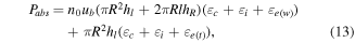
where Pabs is the total power absorbed by the plasma and R and l are the discharge region's radius and length, respectively. The ion mass flow rate and resulting power flowing through the thruster's throat is then given by


Combining equations (7)–(15), we are left with the following unknowns: ng,  , Pabs,
  , and
, and  . For the analysis presented in this paper, we use numerical simulations to determine ng while Pabs,
  , and
, and  are measured experimentally. Given values for these four unknowns and an expression for
  , we can solve iteratively for the variables of interest, namely Pt, Pcex, Pec, and
  . Finally, by holding
  constant over a range of neutral pressures, we can use a single measured value of
  to calculate accelerated ion velocities as a function of background pressure.
In summary, in the previous section, we introduced a series of global power balances to assess how the exhaust velocity of ions exiting the magnetic nozzle will depend on the introduction of neutrals in this region. The prevailing hypothesis is that inelastic collisions will remove thermal energy from the flow, acting as an effective loss term, driving down performance. This is in keeping qualitatively with measurements to date. In the next sections, we examine the validity of this scaling law by employing a controlled experiment in which we characterize changes in ion velocity as a function of facility pressure.
3. Experimental apparatus
The test article we use for this study is a low-power magnetic nozzle thruster that employs ECR heating to energize its propellant. This design is based on the ECR thrusters developed at the Office National d'Etudes et de Recherches Aérospatiales (ONERA), which have measured thrust efficiency as high as 11% at 1000 s specific impulse while operating at under 50 W [5, 25]. These thrusters represent the leading edge of the field in performance, demonstrating marked improvement over previous helicon and inductively coupled magnetic nozzle thrusters, which typically have efficiencies around 1% at specific impulses (Isp) less than 400 s at these power levels [26–28]. Moreover, the ECR thruster is an expedient choice of test article as facility effects at low pressure already have been documented quantitatively for these devices.
3.1. Thruster and vacuum facility
We show in figure 2 the thruster used for this experiment firing in a low-pressure condition. In this design, plasma is generated using ECR heating, in which microwave power is input to the thruster at a frequency matching the electron cyclotron frequency,  , where e is the electron charge, B is the magnetic field strength, and me is the electron mass. For these experiments, we used a 2.4 GHz input frequency corresponding to a resonant magnetic field strength of 859 Gauss.

Figure 2. ECR thruster firing at 30 watts at a flow rate of 1 sccm xenon and a background pressure of 0.9 μTorr.
Download figure:
Standard image High-resolution imageThe magnetic field, which produces both the resonance region for ECR and the expanding magnetic nozzle for ion acceleration, is generated by a set of permanent magnets. The discharge region consists of a coaxial geometry in which TEM microwaves are fed upstream of the resonance zone between a copper center conductor and an aluminum outer conductor, which also serves as the outer wall of the thruster. Propellant is injected radially through a plenum as shown in figure 1. Our experiment uses xenon at a flow rate of 1 sccm for all operating conditions. The entire thruster fits within a 5 cm diameter by 5 cm length cylinder.
The experiments were performed in the Junior Test Facility at the University of Michigan Plasmadynamics and Electric Propulsion Laboratory. The facility measures 1 m in diameter by 3 m in length. The thruster was placed in the center of the chamber, approximately 1.5 m from the end cap, where the thruster's plume terminates. The facility is equipped with both turbomolecular and cryogenic pumps capable of a combined pumping speed of roughly 32 000 l s−1 on xenon. Due to the low pressures and a partial coverage of the cryogenic pump during this experiment, a reduced pumping speed of 19 000 l s−1 was measured. The typical base pressure observed during the experiment was  Torr-N2. In order to vary operating background pressure, we added a second gas injection port at the back of the chamber, as shown in figure 3. We then flowed between 0 and 40 sccm xenon to vary the background pressure.

Figure 3. Schematic of facility and diagnostics with relative positions indicated.
Download figure:
Standard image High-resolution imageWe show a schematic of the overall microwave setup in figure 4. Microwaves are generated by an HP 8363B signal generator. This signal is then amplified by a solid state power amplifier and sampled using a Narda 3022 dual directional coupler attached to two Mini-Circuits PWR-6 GHz power meters measuring forward and reflected power. The microwave power is then fed into the vacuum chamber and to the thruster using a 1.2 meter RG-400 coaxial cable and a DC block to allow the thruster to float electrically. Power losses between the directional coupler and the thruster were measured prior to testing, and forward power at the thruster was held between 19 and 20 Watts for the entire experiment.

Figure 4. Schematic of microwave power injection.
Download figure:
Standard image High-resolution image3.2. Diagnostics
We characterized thruster operating conditions and performance by measuring forward and reflected microwave power, chamber pressure, and ion velocities. We measured forward and reflected power at the microwave amplifier (outside of the vacuum chamber) using the directional coupler and power sensors described in the previous section. Pressure was measured at the chamber wall using a Stabil Series 370 Ion Gauge (calibrated for nitrogen) mounted in plane with the thruster. The low pressures involved in this experiment necessitate that we take into account the finite base pressure when correcting the readings for xenon. Pressures reported in this experiment are therefore calculated using  , where 2.87 is the correction factor from nitrogen to xenon.
The LIF diagnostics employed in this experiment are based closely on previous studies described in [29, 30]. A tunable laser pumps the 834.953 nm (vacuum) metastable excited state of Xe II, which then emits a 542.066 nm (vacuum) photon as it relaxes to the Xe II ground state. We deduce ion velocities using the Doppler shift between the tunable input laser wavelength and the known 834.953 nm transition, given by

where c is the speed of light, ν is the input frequency, and  is the metastable transition frequency. The exact setup is described in more detail in [29].
The large magnetic fields near the thruster may impact our measured VDFs through the effect of Zeeman splitting. Following Huang [31], at the maximum magnetic field strengths encountered by our LIF measurements (∼400 G), we anticipate that Zeeman splitting will lead to symmetric broadening of the IVDF by ∼910 m s−1. While at the exit plane this splitting is commensurate with the bulk velocity, moving further away from the source, the relative effect decreases as the ions are accelerated and the magnetic field drops from ∼400 Gauss at the exit plane to under 50 Gauss midway through the acceleration region. Here, the calculated fractional shift is less than 1%. Moreover, we infer the average velocity by fitting normal distributions to the data, which effectively removes the effect of this symmetric splitting. Zeeman splitting thus is ignored in our analysis.
4. Results
In this section, we present experimental results quantifying the impact of increasing background pressure on the dynamics of the magnetic nozzle. We then compare this data to the predictions of the model outlined in section 2. To this end, we first report our measurements of facility pressure and neutral density. We then investigate the role of facility pressure on the RF coupling to the plasma. Finally, we present the measured ion velocities in the magnetic nozzle at each of the three background pressures tested. We conclude by interpreting these results in the context of the governing relations resented in section 2.
4.1. Neutral density in source and plume
We calculate neutral density in the discharge region using the COMSOL Multiphysics Free Molecular Flow solver. We use a simplified axisymmetric model of the thruster and vacuum chamber to generate a mesh and subsequently solve for the neutral density at each point within the thruster and chamber. We then average over the densities within the source to obtain ng. The simulations predict that for one sccm xenon,  . An approximate calculation for ng can be performed using a 0D particle balance model:
  , where m is the atomic mass, v is the bulk velocity of particles exiting the throat, and A is the throat area. Here, we expect v to be between the velocity predicted by free molecular flow,
  , and that predicted by sonic flow,
  . Using a standard temperature of T = 300 K, we calculate that ng predicted by our simulation is approximately halfway between these values.
We approximate neutral density, which includes contributions both from the plasma source and the background gas, as constant throughout the chamber (and therefore plume region). This approximation is justified by the relatively high (>50%) mass utilization efficiency predicted by our model, meaning that most neutrals coming from the thruster are produced during recombination on the chamber walls. The neutral densities derived from our pressure measurements are shown in table 1.
Table 1.
Neutral density in the plume,  .
.
| Pressure, μTorr |
 , m−3 , m−3 |
|---|---|
| 0.98 |

|
| 13 |

|
| 26 |

|
4.2. Microwave power coupling
The first check we make on the role of facility pressure in thruster performance is to determine if changes in background neutral density can affect how RF power is coupled to the plasma. To this end, we measured the forward and reflected microwave power as a function of facility pressure (figure 5(a)). We translate these measurements to reflection coefficients and load impedances in figure 5(b). Here, the microwave reflection coefficient, Γ, is defined as  , where Pinc and Prefl are the incident and reflected powers, respectively. The load impedance is found using
  , where Z0 is the coaxial cable impedance, 50 Ω. We ultimately see that the that the load impedance, ZL, varies by less than 4% over the conditions tested, indicating that plasma loading remains relatively unchanged for the range of background pressures produced in the experiment. This is physically intuitive as the neutral density in the source is an order of magnitude higher than in the plume and thus is expected to be relatively impervious to the variations in the lower density plume.

Figure 5. (a) Forward and reverse power and (b) Γ and ZL as a function of chamber background pressure.
Download figure:
Standard image High-resolution image4.3. Ion VDF measurements
In this section, we present our measurements of ion velocity and acceleration along thruster centerline as functions of facility pressure. Typical shapes of the IVDFs we measured in the near and far-field of the nozzle are shown in figure 6. Here, we have overlaid a fitted skewed-Gaussian distribution that we use for determining most probable velocities and calculating error. In the near-field, the IVDF for all background pressure conditions is characterized by a single, well-defined peak indicative of a near-mono-energetic drifting population. Moving downstream, the IVDFs differ in shape between the low and high pressure conditions. The low pressure (0.98 μTorr) IVDFs maintain a single, well-defined peak throughout the plume. The higher pressure cases, on the other hand, exhibit a broad, non-Maxwellian IVDF downstream of the exit plane. We can still observe a high velocity peak, reflecting an acceleration of the bulk ion population. However a second peak forms around 2000 m s−1. Between these two peaks, we observe a spreading of the accelerated population to lower velocities. The stationary population and low energy tail of the accelerated ions are indicative of ions that are created at different positions in the nozzle and therefore experience different levels of acceleration. This is indirect evidence of downstream ionization or charge exchange collisions between ions and neutrals.

Figure 6. Axial ion velocity distribution function traces along center-line for the 13 μTorr condition at (a) exit plane of the thruster, and (b) 85 mm downstream of the exit plane.
Download figure:
Standard image High-resolution imageFigure 7 further supports the idea that this lower energy population can be attributed to inelastic collisions in the plume. In these figures, we show the spatially-resolved LIF data as intensity plots where the VDFs are normalized to unity for each axial position. In these three cases, the power to the thruster remained the same, 20 W, but the facility pressure was increased from 0.98 to 26 μTorr-Xe. The data show that ion acceleration takes place over the region spanning from the exit plane to roughly 100 mm downstream. The overall shape of the acceleration profile is similar for the three pressures tested. However, the signal-to-noise ratio decreases by a factor of two as pressure is raised, and the low energy population becomes increasingly evident—suggesting more ions are being created in the plume at higher background pressures. Moreover, in all three cases, although the ion velocity asymptotically approaches a maximum downstream, the final value decreases with increasing pressure. This reduction in maximum achievable directed kinetic energy is consistent with the observations reported in [9].

Figure 7. Xe II velocity distributions along thruster axis at (a) 0.98 μTorr, (b) 13 μTorr, and (c) 26 μTorr background pressure conditions. The colorbar represents the collected light intensity with peak intensity normalized to 1 for each axial position, and values are interpolated between data points. Distances are measured from the thruster exit plane.
Download figure:
Standard image High-resolution imageWe convert the intensity maps in figure 7 to a single metric for ion acceleration by calculating the most probable velocity of the ions at each spatial location. To this end, we fit a skewed-Gaussian distribution to the high-velocity population in each IVDF and assigned the mean value to the drift speed, as shown in figure 6. The uncertainty in these drift values, in turn, was determined by re-sampling and curve fitting each IVDF using a boot strapping method. Following this technique, we show in figure 8 the resulting values of ion speed and ion kinetic energy,  . Here we can see explicitly the direct impact of increasing pressure. As pressure increases from 0.98 to 26 μTorr, ion velocities decrease by ∼20% from 12.8 to 10.2 km s−1, correlating to a decrease in ion energy of ∼37% from 111.5 to 70.4 eV.

Figure 8. (a) Most probable velocity of accelerated ions, (b) ion energy deduced from LIF data as measured from the exit plane of the thruster.
Download figure:
Standard image High-resolution image4.4. Power lost to electron–neutral and CEX collisions
The key remaining unknowns affecting power losses within the magnetic nozzle are the electron temperature, Te, the plasma density, ne, and the energy lost per electron at the throat,  . To estimate these values experimentally from our available data, we make a few key additional assumptions. First, we assume that 100% of the power input to the thruster (20 W) is absorbed by the plasma. Though this is an overestimate, given the low reflected powers seen during the experiment (section 4.2), the actual value may be close to this number. Additionally, as we discuss in section 4.5, the final ion velocities predicted by our model are independent of absorbed power, so long as
  is constant. Second, we take
  to be zero in the model, corresponding to an open boundary condition. This is justified for our experimental setup by noting that the thruster's position is several acceleration region lengths from the nearest vacuum chamber walls [23]. Finally, we use a CEX cross section of
  m2 corresponding to ∼1 eV ions. Because
  monotonically decreases with ion energy, this represents an upper bound for Pcex. Armed with these assumptions and the measurements of ion velocity, neutral density, and power coupling, we can evaluate the expressions given by equations (1)–(15) to determine the power fluxing into the throat and the power lost to electron–neutral and CEX collisions. We show these values in table 2. We also plot the relative power consumed by CEX and inelastic electron–neutral collisions in figure 9.

Figure 9. Relative powers consumed by electron and CEX collisions.
Download figure:
Standard image High-resolution imageTable 2. Plasma properties and collisional power consumed in the plume for the background pressures tested.
| P, μTorr | Te, eV |
 , eV , eV |
ne, m3 |
 , kg s−1 , kg s−1 |
Pt, W | Pcex, W | Pec, W |
|---|---|---|---|---|---|---|---|
| 0.98 | 10.6 | 113.8 |

|

|
5.53 |

|
0.09 |
| 13 | 10.6 | 111.9 |

|

|
5.47 |

|
1.22 |
| 26 | 10.6 | 132.2 |

|

|
6.03 |

|
2.35 |
From these calculations, we can observe that over a third of the power entering the throat is consumed by electron–neutral collisions within the plume as pressure rises above 20 μTorr, while no significant power losses can be attributed to ion-neutral CEX collisions. More realistic cross sections for the CEX collisions at higher energies would yield even lower values for Pcex, further confirming this point. This suggests quantitatively that electron impact ionization and excitation play the leading role in downstream power consumption, with values comparable to the total energy leaving the nozzle.
4.5. Model comparison
In this section, we explore the predictive capabilities of the model we presented in section 2 by using the data from a single operating condition to predict the ultimate ion velocities for a range of background pressures. In our analysis, we use the data from the lowest background pressure measurements. This data point was chosen due to its high signal to noise ratio, but is otherwise an arbitrary choice. The velocity and pressure measurements for this single point inform the value of  in our model, which we then hold constant over all background pressures. This is equivalent to assuming that changes in the plume do not affect the discharge upstream of the throat. The data in table 2 show that this assumption may break down at high background pressures. However, as we show below, our model has good first order agreement.
Rearranging equation (1), we can relate accelerated ion energy to normalized power losses in the plume,  , where Pt is the power entering the throat:
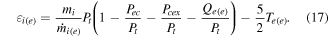
Using this relation, we can calculate predicted ion energies with respect to normalized power losses,  , where
  . These results are plotted in figure 10(a). Here, we have overlaid the data at each background pressure presented in table 2 with error bars generated by the uncertainties in the LIF measurements.

Figure 10. Measured and predicted ion velocities for  ranging from 0 to 0.5, including sensitivity analysis of ng,
  , and
, and  .
.
Download figure:
Standard image High-resolution image
Figure 10(a) shows that the final ion energies scale roughly linearly with power consumed by plume collisions, as is predicted by equation (1). This is a direct initial confirmation that the loss in electron energy that stems from collisions with these species may be sufficient to explain the degradation in performance of the nozzle with pressure. With that said, this conclusion is subject to a number of simplifying assumptions about the value of  , as well as the other parameters governing equation (1). To test the rigor of our result, we therefore relax these assumptions parametrically to determine the sensitivity of our results to these assumptions.
We do this sensitivity analysis in three ways. First, we examine the role of neutral gas density in the thruster, ng, as we have made the simplifying assumption that this is constant and can be estimated from a numerical model. We allow this value to vary by +/−50%. Second, we allow the electron temperature within the plume,  , to vary by +/−50%. This is an important parameter to consider as we were not able to measure it directly in the near-field region of the plume and it is critical to the ultimate acceleration process of the thruster. Third, we vary the electron heat flux at the nozzle exit,
  from 0 to
  , corresponding to an open boundary and sheath boundary condition, respectively. Arguably, the electron heat flux is one of the least understood and hardest parameters to measure in these devices. We elect to employ these two boundary conditions as they represent the extremes in the values of this flux. We note that we forgo a sweep of Pabs as it can be shown that both
  and
and  are independent of Pabs. Thus for a fixed
  and
and  ,
,  is independent of Pabs.
With this in mind, we recalculated  over each pressure condition and updated the output of equation (17) using the new input parameters. The results of these calculations are shown in figures 10(b)–(d). For each of these figures, the non-swept parameters are held at the conditions shown in table 2. From these figures, we can observe that in all three cases, although the data and model shift (most prominently with discharge region neutral density), the agreement between the two is relatively insensitive to the changing assumptions. This suggests that the conclusion that the loss in ion energy can be attributed to electron–neutral collisions still holds.
5. Discussion
We discuss in the following key assumptions and potential sources of error underlying our analysis and the implications of our results in the context of facility effects and previous work.
5.1. Key assumptions
Free-fall diffusion in main discharge. The free-fall diffusion profile, given in [24], neglects the effect of the applied magnetic field, which likely acts to inhibit diffusion to the radial walls. This would cause the model to overestimate Te and thus underestimate ne. However, given the approximately linear behavior of Kiz and Kex for the electron temperature range of interest ( eV), we expect that
  in the plume will remain roughly constant for small changes in the Te and ne.
No neutral depletion. By neglecting neutral depletion, we have artificially raised the predicted neutral density within the thruster (ng). Because of the relatively high ionization fractions predicted by the model (∼5%), this negation leads to a low estimate of Te and thus a high estimate of ne. For small changes in ng, this has minimal effect of  . However at large ionization fractions (
 %), these effects can significantly alter predicted plume losses, as shown in figure 10(b).
Ions reach Bohm speed at thruster exit. Our primary discharge model assumes that ions reach the Bohm speed at the thruster exit. Measurements on our device and previous studies have shown that this throat location is, in fact, several millimeters downstream of the thruster exit [15]. Collard and Jorns have suggested that this effect is largely due to collisions with neutrals and is a source of inefficiency in magnetic nozzles. We have shown quantitatively how this might be the case. However, because of the complex diffusion dynamics at the open end of the thruster, it is unclear how, exactly, this would affect the main discharge. One challenge moving forward would be to link the location of this sonic transition to the collisional loss term. This is done in traditional nozzles where non-adiabatic and non-isentropic flow move the choking point downstream of the physical throat.
Plume expansion with magnetic field lines and isothermal electrons. The choice of plasma expansion with the magnetic field and isothermal electrons gives us a first order approximation for collisional power consumed in the plume. While this neglects several of the more complex electron cooling and diffusion processes that occur in magnetic nozzles, the sensitivity analysis presented in figure 10(c) shows that our loss model is largely unaffected by plume electron temperature. This is due to the plasma density in the plume scaling inversely with plume electron temperature, partially offsetting the changes in Kiz and Kexc.
Electron temperature unaffected by downstream ionization. By keeping the main discharge electron temperature independent of plume collisions, we have assumed that relatively few electrons generated downstream of the throat drift into the main discharge region. Relaxing this assumption would lead to a lower electron temperature in the discharge as cool electrons back-stream into the thruster. This would in turn lower the acceleration potential as each ion-electron pair exiting the throat carries less energy into the nozzle. Fully capturing this phenomenon requires a more complete picture of electron heat flux in the nozzle, and we therefore do not include these effects in our model. However, it should be noted that previous measurements of the thruster's floating potential showed decreases in the magnitude of the floating potential (with respect to chamber walls) that were greater than corresponding changes in ion energy [32]. This is perhaps indicative of decreased electron temperature inside the thruster at higher background pressures.
Neglect of role of boundary conditions. Finally, it is possible that additional facility effects, such as secondary electrons emitted from the chamber walls, can influence plume dynamics. This can give rise to non-thermalized distributions that fundamentally impact the electron thermodynamics and heat flux. An investigation of these effects is beyond the scope of this paper. With that said, while the good agreement of our global model with experimental measurements would suggest that these other facility effects may not have had a substantial contribution over our range of studied pressures, these effects ultimately may have a more prominent role as pressures are reduced or smaller facilities are employed.
5.2. Implications for thruster testing standards and extrapolation to on orbit performance
The key finding from our investigation is that it is inelastic electron–neutral collisions in the plume with facility neutrals that adversely impact magnetic nozzle thruster performance. This indicates that collisionless models of magnetic nozzle acceleration regions, such as those presented in [22, 23, 33], can accurately describe plume dynamics only for very low background pressures. Having identified a potential cause and validated a model for this effect, we now can turn to the key question of how a thruster will behave in a relevant, space like environment. To this end, in our model, extrapolating to unmeasured pressures requires an expression for  , the energy deposited in each electron entering the throat. The study presented in section 4.5 holds
  constant across all pressures using the value obtained from our lowest pressure results. This choice was somewhat arbitrary, corresponding to the highest signal to noise ratio data gathered during the experiment. However, the results show good agreement at low pressures. It is notable that the trend with facility pressure does appear to change inflection at high pressure, indicating a potentially nonlinear response. This was not captured in our model and could perhaps be attributed to feedback effects such as electron thermalization becoming more important at these higher pressures. With this in mind, at least at lower pressures where there is better agreement between model and experiment, this work suggests a recommendation for how ground tests in the future may be extrapolated to orbit. Most notably, we see that the deviation scales linearly with neutral density. This indicates that we may be able to extrapolate to zero pressure by fitting a line. For example, our current results suggest that ions would achieve a kinetic energy of ∼120 eV on orbit.
6. Conclusion
In an interesting departure from state-of-the-art EP devices such as Hall thrusters, which show a general improvement in performance with increased facility pressure, magnetic nozzle performance decreases with background neutral density. In this work, we have demonstrated that this degradation in performance largely can be attributed to electron–neutral collisions within the plume that significantly reduce the amount of power available to accelerate ions through the diverging magnetic nozzle. By raising the background pressure from 0.98 to 26 μTorr, we calculated that 39% of the power entering the plume, in the form of both ion inertia and electron pressure, is consumed by ionization and excitation collisions. Physically, these collisions remove the critical thermal energy introduced to the electrons in the source region before it can be successfully converted to kinetic energy of the ions. Our calculations for how the loss in energy scales with facility pressure are commensurate with our LIF measurements, which show a broadening of ion VDFs and a reduction in accelerated ion energy of 37%. Practically, our results have two major implications for the field. First, these findings suggest that collisionless models must be augmented to accurately describe plume dynamics in thrusters operating in finite background pressure conditions [22, 23, 33]. Second, we have found that at low densities, the dependence of ion velocity on pressure is linear. This suggests a potential future strategy for mapping ground based tests to on orbit behavior.
Acknowledgments
This work was supported by NASA Space Technology Research Fellowship grant 80NSSC17K0157. The authors would like to thank Eric Viges for his extensive help in setting up the vacuum facilities, Dr Ethan Dale for his expertise on the LIF system, and Shadrach Hepner and Marcel Georgin for their feedback on this manuscript.