
Abstract
It is estimated that pilot plants and reactors may experience rates of net erosion and deposition of solid plasma facing component (PFC) material of 103–105 kg yr−1. Even if the net erosion (wear) problem can be solved, the redeposition of so much material has the potential for major interference with operation, including disruptions due to so-called 'unidentified flying objects (UFOs)' and unsafe dust levels. The potential implications appear to be no less serious than for plasma contact with the divertor target: a dust explosion or a major UFO-disruption could be as damaging for an actively-cooled deuterium-tritium (DT) tokamak as target failure. It will therefore be necessary to manage material deposits to prevent their fouling operation. This situation appears to require a fundamental paradigm shift with regard to meeting the challenge of taming the plasma–material interface: it appears that any acceptable solid PFC material will in effect be flow-through, like liquid–metal PFCs, although at far lower mass flow rates. Solid PFC material will have to be treated as a consumable, like brake pads in cars. ITER will use high-Z (tungsten) armor on the divertor targets and low-Z (beryllium) on the main walls. The ARIES-AT reactor design calls for a similar arrangement, but with SiC cladding on the main walls. Non-metallic low-Z refractory materials such as ceramics (graphite, SiC, etc) used as in situ replenishable, relatively thin—of order mm—claddings on a substrate which is resistant to neutron damage could provide a potential solution for the main walls, while reducing the risk of degrading the confined plasma. Separately, wall conditioning has proven essential for achieving high performance. For DT devices, however, standard methods appear to be unworkable, but recently powder droppers injecting low-Z material ∼continuously into discharges have been quite effective and may be usable in DT devices as well. The resulting massive generation of low-Z debris, however, has the same potential to seriously disrupt operation as noted above. Powder droppers provide a unique opportunity to carry out controlled studies on the management of low-Z slag in all current tokamaks, independent of whether their protection tiles use low-Z or high-Z material.
Export citation and abstract BibTeX RIS
1. Introduction
High duty cycle DT tokamaks starting with pilot plants will need to find solutions to the plasma facing component (PFC) slag problem, i.e. the problems caused by the copious production of debris, estimated to be of order tons/year, resulting from the plasma erosion of solid PFC material [1–5]. Unless properly managed, PFC debris could foul plasma operation by so-called 'UFO'-triggered disruptions, unsafe dust levels, etc. It will be necessary to treat solid PFC materials as 'flow-through', like liquid metal PFCs, with the PFC slag being removed as continuously as possible to minimize the risk of interfering with operation—and to continuously recover co-deposited tritium in the slag. During its dwell time in the vessel, the PFC slag will have to be managed and sequestered until it can be removed from the vessel so that it does not interfere with plasma operation.
One potential solution to the PFC slag problem would employ non-metallic low-Z refractory ceramics such as graphite and SiC, used as an in situ, regularly replenished, relatively thin, of order mm, cladding on a structural substrate resistant to neutron damage. Some of these materials are themselves resistant to neutron damage, such as SiCf /SiC fiber composite materials. The ARIES-AT design, for example, calls for a 1 mm SiC coating on a 4 mm SiCf /SiC substrate for the main chamber walls [6]. Ceramic coatings could provide the basis for a comprehensive PFC solution including slag management and tritium recovery. In JET, carbon deposits disintegrated before they built up beyond ∼100 μm thickness [7, 8], apparently due to thermo-mechanical stress and weak adhesion of ceramic deposits to substrates, see discussion in section 3.1 of [9] (part B); the debris was discovered to have accumulated in cavities safely out of plasma-contact and did not cause UFO-disruptions. Other potential cladding ceramics like Si, SiC, etc may behave similarly to graphite, however, the required database is presently lacking.
Section 2 considers the magnitude, nature and consequences that are likely to attend solid PFC slag generation in pilot plants and reactors. Section 3 describes a separate but closely related matter, which is also of potentially critical importance for high-duty-cycle tokamaks: the option of using powder droppers to surface condition plasma-wetted surfaces by continuously dropping low-Z materials such as B into the operating discharges, whether clad with low-Z or high-Z armor [10–15]. Section 4 describes some candidate material choices for PFC low-Z cladding (armor) material together with supporting rationale. Section 5 considers an example of a possible tokamak operating scenario using thin low-Z ceramic wall claddings. Section 6 is a summary of the key element of the part A paper, namely, a list of major physics questions that will need to be answered in order to be able to make an informed assessment of the viability of the potential solutions described here. A companion paper [9] (part B) discusses the required near- and medium-term tokamak studies on management of low-Z ceramic deposits in divertors, as well as the near-term studies needed to establish an experimental, scalable database on ionic—including fast-loss ion—and charge-exchange (c-x) neutral fluxes to the main chamber walls of tokamaks; these fluxes are the primary drivers of the net erosion of main wall armor, which is the dominant source of PFC slag. Section 7 is a brief overall summary and conclusion.
2. Managing material deposits in pilot plants and reactors to avoid fouling plasma operation
2.1. Estimates of the magnitude of the material deposition problem
In proceeding from present devices to ITER and then to pilot plants/DEMOs and reactors, the annual energy load for the targets and walls,  , will increase ∼101–105 times, see table 1. Very roughly, total gross erosion of PFC materials due to sputtering can be expected to increase similarly.
Table 1. Rough estimates of net erosion rate of the main walls of tokamaks based on assumptions in appendix
| Device |
 (MW)
(MW)
|
 run time (s yr−1)
|
 (TJ yr−1)
| Beryllium net wall erosion rate (kg yr−1) | Boron net wall erosion rate (kg yr−1) | Carbon net wall erosion rate (kg yr−1) | Silicon net wall erosion rate (kg yr−1) | Iron net wall erosion rate (kg yr−1) | Tungsten net wall erosion rate (kg yr−1) |
|---|---|---|---|---|---|---|---|---|---|
| DIII-D | 20 | 104 | 0.2 | 0.13 | 0.11 | 0.08 | 0.39 | 1.0 | 0.16 |
| JT-60SA | 34 | 104 | 0.34 | 0.22 | 0.19 | 0.15 | 0.66 | 1.7 | 0.27 |
| EAST | 24 | 105 | 2.4 | 1.6 | 1.2 | 0.82 | 4.7 | 12 | 1.8 |
| ITER | 100 | 106 | 100 | 77, 601, 292, 2864 | 64 | 44, 541, 532 | 196 | 500, 1871, 934 | 80, 401, 412, 174 |
| CFETR5 | 1000 | 1.2 × 10⁷ | 12 000 | 7800 | 6400 | 4400 | 23 500 | 60 000 | 9500 |
| ST Pilot P6 | 50 | 107 est. | 500 | 330 | 270 | 190 | 1000 | 2500 | 400 |
| ARC Pilot P7 | 100 | 107 est. | 1000 | 650 | 530 | 370 | 1960 | 5000 | 790 |
| Comp. Pilot P8 | 260 | 107 est. | 2600 | 1700 | 3200 | 1000 | 5100 | 13 000 | 2000 |
| Reactor | 400 | 2.5 × 10⁷ | 10 000 | 6500, 21 0003 | 5300 | 3700 | 19 600 | 50 000 | 7900, 50003 |
| 4.3a | 2.9a | 1.8a | 4.2a | 5.4a | 0.26a, 0.16a | ||||
| 3.5b | 2.1b | 1.6b | 8.5b | 6.4b | 0.42b, 0.26b |
Other estimates: 1Behrisch et al [1], 2Kukushkin [2], 3Lackner [3], 4Brooks et al [4]. The estimates in [3] are also for c-x neutrals only; those in [1, 2, 4] include ions as well, generally finding a similar rate as for c-x neutrals. 5CFETR phase II [20]. 6ST-FNSF [21]. 7ARC [22]. 8Compact net electric fusion pilot plant [23]. PSOL (MW) is the SOL heating power and  (s yr−1) is the annual run time. a
 029 atoms yr−1. bSurface recession rate (mm yr−1), assuming uniform wear of a 1000 m2 wall area.
It appears that pilot plants and reactors may experience rates of net erosion and deposition of PFC material in the range of 103–104 kg yr−1, see estimates in table 1. These estimates may be conservative since they are for erosion of the main walls only, i.e. they do not include the divertor targets. Away from the divertor targets, the rate of net erosion is approximately the same as the rate of gross erosion, i.e. sputtering, since prompt local re-deposition is not effective due to the long ionization distances for low plasma density. Lackner has estimated that for an all-tungsten PFC reactor, the net erosion due just to charge exchange neutral particle impact on the main walls (i.e. neglecting wall erosion by ions and all divertor erosion), will be ∼5000 kg yr−1 [3]. Recently, detailed analysis of erosion rates of tungsten at the main walls of EU DEMO [16] has been carried out that includes the contributions to sputtering of both ions and c-x neutrals [17, 18]; for an ITER-like wall (ILW) clearance of 5 cm and for the reference plasma case, the net erosion estimate is ∼15 000 kg W fpy−1 (full power year) and ∼2500 kg W fpy−1 for a wall clearance of 15 cm [17].
Experimental information for the first three JET ILW campaigns for Be is also available [19]. The average rate of Be deposition measured post mortem in the divertor for the three JET campaigns, 2011–2016, is 280 µg MJ−1 (from table 2 of [19]) which may be compared with the rate of 650 µg MJ−1 = 0.65 kg TJ−1 from [5] and appendix
Such large values of  , of order 1016 J yr−1, mean that a fusion reactor is likely to be as much a chemical/materials reactor as a nuclear reactor. Modern steel blast furnaces, for example, involve similar values of
  [24]. It appears unavoidable that large quantities of material will flow through fusion reactors, transforming the material properties in the process.
Such rates of net erosion—and the resulting deposition—are far greater than anything experienced to date in magnetic fusion energy (MFE) devices. Even if the net erosion (wear) problem can be solved by frequent vessel interventions or by periodic in situ refurbishment using advanced robotics or other means, the deposition of such massive quantities of material has the potential to interfere with pilot plant and reactor operation, including:
- (a)High levels of dust due to exfoliated and spalled deposits, with the attendant risks of dust explosion, mobilized tritium and other radio-activate elements, etc.
- (b)For non-metals: disruptions caused by exfoliated/spalled material entering the plasma—so-called UFO-disruptions.
- (c)For metals: disruptions caused by the melting and splashing of deposits which have evolved to become proud of power-loaded surfaces.
- (d)Other adverse effects due to buildup of unwanted eroded material at critical locations, such as metal-bridging of PFC tile gaps, which could result in cracking of the coolant channels due to eddy currents and thermal stresses.
It will therefore be essential to manage material deposits to prevent their fouling pilot plant and reactor operation by PFC slag and to recover tritium co-deposited in the slag. As discussed below, this could, in principle, be done using graphite-clad or other refractory, non-metallic, low-Z ceramic cladding such as SiC.
Low-Z elements are of particular interest for the armor of the main wall because of the relatively high concentrations of low-Z impurity ions that can be tolerated in the confined plasma before ignition is prevented, see figure 1(a). By this measure, the advantage of low-Z elements over tungsten is 2–3 orders of magnitude; this factor more than offsets the comparative sputtering yield (in atoms) which is about one order of magnitude higher for low-Z elements than for W, see last line of table 1.
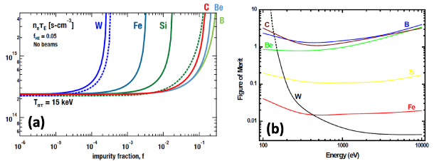
Figure 1. (a) The minimum value of  (at T = 15 keV) required for ignition as a function of (non-He) impurity fraction, f, assuming 5% concentration of He in the confined plasma. The dashed lines assume coronal equilibrium; the solid lines assume non-coronal equilibrium with a 10 ms dwell time for the impurities. See detailed discussion in appendix
  , and is displayed as a function of the impact energy of the charge-exchange neutrals striking the main wall. Higher values of the FOM indicate more favorable materials.
Download figure:
Standard image High-resolution imageA simple measure of the advantage of low-Z vs high-Z elements is the figure of merit (FOM), defined as the ratio of the maximum allowable plasma concentration to the sputtering yield:  , see figure 1(b). The maximum allowable concentration is taken from figure 1(a) for
  s cm−3. The sputtering yields are estimated by a procedure similar to that used for table 1, as described in appendix
High retention of tritium in low-Z co-deposits at low temperature may be the biggest impediment to the use of low-Z material in an actively-cooled DT device. For the water-cooled ITER, this was the reason for replacing the originally planned graphite targets with tungsten [8]. Economically viable commercial fusion reactors, however, will ultimately operate with coolant temperatures of ∼1000 °C in order to achieve high thermal efficiency, see the discussion in section 4. At such temperatures, it is known that there is little hydrogenic retention in carbon, section 4. Studies have now started on other low-Z materials, such as SiC [27, 28], but the needed databases still need to be established.
2.2. Net erosion from the divertor targets
Due to the increase in  of roughly five orders of magnitude, the gross erosion due to sputtering per operating-year near the divertor strike points of pilot plants and reactors is likely to be higher than in present devices by a roughly similar factor. The measured rate of net erosion in present devices is 0.1–10 nm s−1 [29], thus for a typical
  s yr−1 operation the rate of target surface recession is only
  –
– m yr−1. However, if net erosion were to also scale up by five orders of magnitude, then for pilot plants and reactors the rate of recession of the target surface would be an unacceptable 0.1–10 m yr−1. The divertor conditions planned for devices like ITER involve partial detachment, as discussed further below, namely Te < ∼5 eV and ne ∼ 1021 m−3 near the strike-points which, fortunately, are such as to strongly suppress net erosion relative to gross erosion due to prompt local deposition of sputtered particles: when the ionization mean free path for the sputtered impurity neutral Lioniz is less than the fuel ion Larmor radius
  , then the strong E-field force in the magnetic pre-sheath, which is of thickness LMPS = 3–10
  , promptly returns the ionized impurity to the target [30, 31]. For Te ∼ 5 eV and ne ∼ 1021 m−3, Lioniz
< LMPS for both high-Z elements like W and low-Z ones like C, see figure 4 in [32].
, promptly returns the ionized impurity to the target [30, 31]. For Te ∼ 5 eV and ne ∼ 1021 m−3, Lioniz
< LMPS for both high-Z elements like W and low-Z ones like C, see figure 4 in [32].
2.3. Net erosion from the main walls
We consider next the main walls of the vessel where substantial net erosion appears to be unavoidable as a major source of PFC slag in pilot plants and reactors, table 1. The estimates in table 1 are conservative in that they are approximately what is expected for c-x neutrals alone; plasma (ion) contact with the main chamber walls in divertor tokamaks has been found to be significant, see example of DIII-D shown in figure 2, and therefore the values in table 1 may be underestimates, see [17, 18], also section 2 of part B [9]. As well as causing sputtering itself, plasma wall contact, through recycling, is likely to generate most of the c-x neutral fluxes to the main-walls on which the estimates in table 1 are based. As reactor-relevant edge conditions are approached (i.e. the plasma density is raised to approach detached divertor operation), the total ion flux to the main chamber walls can become greater than the total ion flux to the divertor targets and can approach levels comparable to the ion flux to the target during attachment [33]. Similar behavior was first reported in C-mod and has been termed main chamber recycling [34].

Figure 2. In DIII-D [33], as detached divertor operation is approached, the total ion flux to the main chamber walls, Iwall, becomes greater than the total ion flux to the divertor targets, Idiv, as first reported in C-mod and termed main chamber recycling [34]. Outer divertor detachment starts at  here. Reproduced from [33]. © IOP Publishing Ltd. All rights reserved.
Download figure:
Standard image High-resolution imageAs already noted, the processes of prompt, local (re-)deposition of impurities cannot be expected to be effective at the main walls where the plasma density is low and thus the ionization distance for sputtered atoms is long. Therefore, at the main wall, on poloidal average the net erosion rate will be approximately the same as the gross erosion rate. A critically important implication of this is that for detached divertor conditions, where the targets will be regions of material deposition, erosion of the main wall is likely to be controlling impurity behavior generally in the device: 'in full detachment... the main-wall source may completely dominate the impurity sources and the core plasma contamination' [33].
This situation poses a major challenge; however, it also has the potential to provide a solution to the overall PFC problem in pilot plants and reactors, as will be discussed.
The ion-wall contact can directly cause substantial annual net erosion of material for 107 s yr−1 high duty cycle operation [17, 18]. The indirect effect of the plasma-wall contact, however, can be still more serious since it can result in energetic charge exchange (c-x) neutrals, D0 and T0, impacting the wall. EIRENE code calculations for ITER conditions report average c-x energies at the outer midplane (the most intensely bombarded location) of ∼0.6 keV, with 20% of the c-x atoms having >1 keV energy [35]. The c-x neutrals can be considerably more energetic than the ions in the thermal plasma contacting the main wall surfaces, while their total fluxes are comparable.
In current tokamaks, the main wall generally tends to be in a (spatially-averaged) state of net erosion, with the lost material being largely transported to the divertor where it accumulates [7, 8]. In detached conditions in DIII-D virtually the entire divertor—both outer as well as inner targets—can be in a state of net deposition due to PFC material migration from the main walls [29]. In ITER, where both targets will be partially-detached, the base case assumption is that 'Be eroded from the main chamber walls is assumed to migrate everywhere into the divertor, coating the targets' [36, 37].
A long standing concern in MFE research has been excessive net erosion (wear) of reactor targets. However, in light of the copious net erosion of material from the main walls and its migration to the divertor, target wear would appear not to be the problem after all. For pilot plants and reactors, the entire divertor could be—or could be arranged to be—in a state of net deposition due to the copious migration of eroded material coming from the main walls. Such migration of wall material could compensate—even greatly over-compensate—for the net erosion that could otherwise occur at the strike points. Because of the large wall area, the wall erosion-wear may be tolerable provided it is not spatially concentrated, see estimated recession rates in the last line of table 1. The problem, however, will be to clear the PFC deposits out of the divertor rapidly enough to avoid disrupting plasma operation, i.e. to avoid fouling of operation by PFC slag. In this case, it would be necessary that any acceptable solid PFC material be in effect flow-through like liquid metals, although at orders of magnitude lower mass rates. In this situation, it would be appropriate to think of PFC cladding material as a consumable like brake pads in cars. Eroded brake pad material causes little problem, but the situation for eroded PFC cladding material will be just the opposite: it will be critically important to be able to remove in situ the deposited PFC cladding material transferred into the divertor before it interferes with operation; it will be equally critical to recover as much of the co-deposited tritium in the slag as possible.
Operating the divertor with cold, dense plasma conditions across the target should therefore doubly protect the target armor from erosion-wear: (a) the target surface will be covered by wall PFC slag most of the time thereby shielding it, and (b) during the intervals when the slag covering may be temporarily lost exposing the target armor, the net erosion may be small in any case [32], as discussed in section 2.2. For partially detached operation—as planned for ITER—where only the region near the strike point is detached and with hot plasma further away—net erosion will occur away from the strike point, although at relatively slow rates due to the low ion flux density there. If such wear rate is unacceptable, low-Z powder entrained in D2 gas injected between tiles could potentially provide a solution, see [9] (part B).
Although massive generation of PFC slag from net wall erosion and coverage of the targets with wall material will pose major challenges for pilot plants and reactors, it will also bring an important potential benefit: when the plasma 'sees' only wall PFC material, options are increased for the choice of the target armor material: it need not be plasma-compatible, nor have low potential for co-deposition retention of tritium, etc.
2.4. A case study of the impact of low-Z slag: disruptions in Tore Supra caused by UFOs from just ∼1 kg of net carbon deposition
In 2007, Tore Supra, operating with graphite PFCs, ran 18 000 s of repeat discharges in a 2 weeks campaign dedicated to generating substantial net erosion and deposition with the objective of better assessing deuterium (tritium) retention by co-deposition in carbon slag. An unanticipated operational problem was encountered: the deposits significantly interfered with operation by causing frequent disruptions due to UFOs:
'The main operational issue was linked to the appearance of UFOs (i.e. large particles with a high impurity content, detached from the wall, PFCs or antennas, and penetrating into the plasma), whose frequency increased dramatically during the campaign, triggering a phase of plasma detachment followed by a disruption in a number of cases .... The continuous increase of the UFO frequency is believed to be related to the build-up of thick deposits in the shadowed regions of the toroidal surface...' [38].
In order to generate a significant amount of eroded material, the input power had to be reduced from the ∼10 MW capability of Tore Supra to 2 MW, and the pulse length had to be significantly reduced, requiring longer run time. Following the campaign, an extensive cleaning of the vessel recovered 0.79 kg of carbon deposits [39]. While by present tokamak experience this is a very large quantity of deposited material, for ITER such amounts of deposition may occur every week of full power operation, table 1.
The 1997 JET DT campaign, carried out with graphite walls and targets, generated a similar amount of carbon slag, ∼1 kg, see [7, 8] and the detailed discussion in section 3.1 of [9] (part B). The deposits on the inner target disintegrated before they built up beyond ∼100 μm thickness evidently due to thermo-mechanical stress and the typically weak adhesion of ceramic deposits to substrates, particularly in the divertor region. In sharp contrast with the Tore Supra experience, however, the carbon slag accumulated harmlessly in the pump cavity adjacent to the divertor target, out of plasma-contact—and did not cause UFO-disruptions in the high-power high-performance JET DT discharges. The reason for this extremely fortunate difference is not well understood, but it needs to be since major reductions of the power and duration of these JET discharges could have compromised the landmark JET DTE1 experiment.
The operation of stellarators has been similarly affected adversely by PFC slag:
'Three-dimensional trajectories of incandescent dust particles in plasmas were observed with stereoscopic fast framing cameras in a large helical device (LHD)... ICRF heated long pulse plasma discharges were terminated with the release of large amounts of dust from a closed divertor region. After the experimental campaign, the traces of exfoliation of carbon rich mixed-material deposition layers were found in the divertor region.... Dust transport simulation including heavy metal dust particles demonstrates that high heating power operation is effective for shielding the main plasma from dust penetration by an enhanced plasma flow effect and a high heat load onto the dust particles in the peripheral plasma.... It also shows that tungsten dust particles have a powerful penetration characteristic into the main plasma compared to that of carbon and iron dust particles because of the large inertial effect and the high boiling point.... Control of the size of tungsten dust particles can be a critical issue for sustaining steady-state plasma discharge operation in future nuclear fusion reactors because of the large cooling rate of high-Z materials on plasmas' [40].
The operating problems encountered in Tore Supra may have been specific to carbon slag and to a limiter-tokamak. In light of the significantly incomplete understanding of slag behavior in MFE devices, however, it might also be said that JET was just lucky and Tore Supra unlucky. It now would seem imprudent to assume that significant operational problems will not occur when deposition rates of the order of kg yr−1 are involved, regardless of the specific slag material or MFE configuration. The situation for devices after ITER starting with pilot plants appears to be appreciably more serious. The principal thesis of this report is that understanding and management of slag behavior in solid armored MFE devices will be essential for fusion power development.
3. Continuous surface conditioning using powder droppers
'Proper wall conditioning has turned out to be an essential element for achieving the highest possible plasma performance in present day fusion devices'; this, the opening sentence in Winter's 1996 seminal review on wall conditioning [10], holds even more true today with the change from graphite to high-Z metal PFCs in many MFE devices [41, 42]. For reactors, however, Winter noted: 'thin wall coatings will be rapidly eroded or buried by co-deposited material in future long pulse devices. In situ techniques for replenishment such as plasma fueling by reactive gases or pellets or in situ plasma spraying of components between discharges will have to be developed'. With more recent technological advances, however, it turns out that the challenge for pilot plants and reactors is likely to be less how to replenish the B, C, Si, Li, etc coating material, than how to remove the resulting waste material from the vessel before it interferes with operation; the critical challenge could well be safe management of low-Z slag—i.e. precisely the same challenge described above for use of low-Z main-wall armor. Recently, powder droppers used to inject low-Z surface conditioning material ∼continuously into operating discharge plasmas have been demonstrated to be quite effective [11–15] and may be usable in pilot plants and reactors as well. The resulting massive generation of low-Z debris, however, has the same potential to seriously disrupt tokamak operation, as described above.
Continuous surface conditioning and low-Z wall cladding thus turn out to share the same challenge of safely managing low-Z slag to prevent interference with tokamak operation. In both cases, there will also be the benefit of continuous recovery of tritium from the vessel: most of the retained tritium will be co-deposited in the low-Z slag. In the JET DTE1 campaign, ∼96% of the tritium that was retained in the vessel was found in the carbon co-deposits on cold surfaces in and below the inner pumping duct, as measured ex situ after the experiment [7, 8], see figure 1 in [9] (part B) and the detailed discussion there. As noted earlier, in order to achieve high thermal efficiency commercial fusion reactors will ultimately operate with coolant temperatures of ∼1000 °C, section 4, with the plasma facing surfaces yet hotter. At such temperatures, there is little tritium retention in carbon, see figures 3(a) and (b); it seems possible that other low-Z materials such as SiC will behave similarly, however the database needs to be established. Nevertheless, it will be critically important to recover as much residual tritium in the slag as possible. Careful design of heat management will also be essential to avoid cold corners and cavities in the vessel where highly tritiated deposits can accumulate.

Figure 3. (a) Retained amounts of D and H in graphite as a function of temperature during loading by ions in accelerator facilities [56]; the internal references are listed in the supplementary document (available online at stacks.iop.org/PPCF/64/055018/mmedia). Further studies are needed to extend measurements to lower impact energies relevant to reactor divertor conditions, <100 eV and for loading temperatures up to at least 1200 °C. (b) Temperature dependencies of saturated surface concentrations of H as an atomic ratio, H/C, for carbon tiles taken from various locations in JT-60U; also shown are the H/C values for H-ion-irradiated graphite measured using a laboratory accelerator (continuous line with black dots) [57–61]. (c) Estimated tritium inventory for ITER-like discharges in a full carbon tokamak operated with a base temperature of ∼300 °C based on H + D retention observed in JT-60U [58–61]; also shown is the estimation for ITER with full carbon reported earlier by Roth et al for the somewhat lower temperature at which the water-cooled ITER will operate, ∼200 °C [63]. Even a small increase in operating temperature can reduce the T-inventory in an all-carbon machine by an order of magnitude or more. Reproduced from [58], with permission from Springer Nature. (d) Measured deuterium concentrations in different wall materials as a function of surface temperature [62, 63] extrapolated here for carbon (dashed lines) to reactor wall surface temperatures. Experimental measurements are needed for >600 °C. Reprinted from [62], Copyright (2019), with permission from Elsevier.
Download figure:
Standard image High-resolution imageThe challenge of managing the low-Z slag resulting from continuous surface conditioning will not only be qualitatively similar to the challenge of managing the low-Z slag from the main wall armor, but it appears that it will be quantitatively similar as well. Powder injection rates employed in present tokamaks [11–15] range up to 500 mg s−1, i.e. ∼16 000 kg fpy,−1 which is comparable to the rates of net erosion of the main wall armor, table 1. If the required rate of powder injection scales with Pheat then the resulting low-Z slag generation rate could be an order of magnitude greater.
Powder droppers provide a unique opportunity to perform controlled experiments on the management of low-Z slag in all presently operating tokamaks, independent of the material used for their protection tiles. For dedicated and controlled experiments, substantial amounts of low-Z material could be injected in a short period of time in order to create thick enough layers to be able to carry out useful studies. By contrast, natural erosion rates are too small to create thick deposits quickly, and in any case, this could only be done in tokamaks having low-Z protection tiles.
Recent work on ASDEX-U using boron and BN powder injection into discharges has shown that surface conditioning occurs similar to that from traditional boronization, i.e. oxygen levels decrease as does plasma material interaction wall erosion, see figure 8 in [12]. Subsequent experiments on DIII-D also showed surface condition effects, and fairly uniform thin-film formation was measured using DiMES with composition very similar to that measured for traditional boronizations [14]. In EAST, Li granule injection has also been successful in edge localized mode mitigation [11, 15].
4. Candidate low-Z refractory materials for the main walls
Non-metallic, refractory, low-Z ceramics, used as an in situ replenished, thin cladding on a substrate which is resistant to neutron damage could provide a potential solution for pilot plant and reactor tokamaks:
- Graphite and most other low-Z ceramics are solid, non-melting, refractories...
- ...yet many of these materials are conveniently and routinely introduced into ultra-high vacuum vessels as a gas, e.g. as CH4, B2H6, SiH4, etc, for in situ coating by chemical or physical vapor deposition or plasma assisted chemical vapor deposition (CVD).
- Carbon and other low-Z elements are quite satisfactory as a plasma-facing material regarding the effect on the plasma: they radiate well in the edge plasma and are tolerable at relatively high concentrations in the central plasma, see figure 1(a).
- Some low-Z ceramics such as graphite are unsuitable as a structural material for prolonged exposure to neutrons due to swelling; however, as a thin (order mm) cladding, the time between refurbishments could be less than the time to accumulate levels of neutron damage which would compromise the integrity of the cladding.
- SiC, on the other hand, is known to be exceptionally resistant to neutron damage [43–50].
'Nuclear grade SiC/SiC composites have been proven to be neutron-irradiation resistant at elevated temperatures in terms of retention of mechanical properties, which is a reason that this material is one of the leading candidate nuclear materials for applications including fusion reactor components' [50].
- As already noted, for thermodynamically efficient operation, the reactor coolant temperature will be 600 °C–1000 °C, with the plasma facing surfaces yet hotter. At such temperatures, there is little tritium retention in carbon, see figures 3(a) and (b), and it seems possible that other low-Z materials will behave similarly, however the databases are much less complete. Highly sophisticated heat management design is already a paramount requirement for controlled fusion reactors to ensure that no vessel component gets too hot; for tritium inventory control it will also be a paramount requirement that no corner or recessed location in the vessel gets too cold. Achieving both will require optimizing heat management. It is also necessary to bear in mind that, due to displacements in materials caused by neutrons, the retention properties of all materials including even low-Z ones at elevated temperature, may be different than expected due to the potential for new extrinsic traps to form; it will therefore be important that neutron-damage studies also include low-Z materials at high temperature.
- The quite possibly incompatible requirements that a PFC material be satisfactory with regard to both plasma and neutron interactions would be dealt with by a 'separation of function' design: the substrate material for the main wall armor need not be plasma-compatible, which would open up more options.
- Coverage of the targets with wall material would also open up more options for the target armor material: when the plasma does not 'see' the target material it need not be plasma-compatible, nor have low potential for co-deposition retention of tritium, etc.
- Because the low-Z layer on the main walls would be frequently refurbished, e.g. yearly or more often, it would be thin, ∼order mm, which is important for tritium breeding and is also advantageous for heat transfer.
- For plasma-wetted surfaces at the main chamber walls experiencing net erosion, e.g. antennae, powder dropping of low-Z material ∼continuously into operating discharge plasma could be used to refurbish eroded layers; also, injection of low-Z powder in D2 carrier-gas into the plasma at tile gaps adjacent to regions of net erosion due to plasma contact could be used. On the other hand, continuous powder dropping seems unlikely to be effective for refurbishing the main wall armor eroded by c-x neutral sputtering since the powder material will only reach the parts of the main wall that are plasma-wetted.
- The divertor would be operated in detached or semi-detached conditions so that both inner and outer targets of single null configurations, and upper and lower targets of double null configurations, would be arranged to be in a state of net deposition due to transfer of low-Z material from the main walls. As noted, the challenge would then not be erosion-wear of the target PFCs but the regular removal of the low-Z deposits to avoid fouling plasma operation.
- Selected areas near the divertor out of direct plasma contact would be used to collect and sequester the low-Z deposited material for eventual removal from the DT tokamak, along with residual co-deposited tritium in the low-Z slag; see the extended discussion in part B [9].
- During its sequestration within the vacuum vessel, the collected debris would be baked by externally-controlled heaters to thermally desorb residual tritium continuously, without need to break vacuum.
As noted, commercial fusion reactors will ultimately operate with coolant temperatures of ∼1000 °C in order to achieve high thermal efficiency. The plasma-wetted surfaces will thus be yet hotter. The ARIES-AT reactor design, for example, calls for a 1 mm CVD SiC armor layer on a 4 mm SiCf /SiC structural main wall [6, 51], see figure 4 here, also section 4.1; the LiPb coolant will be at ∼1000 °C. The EFDA fusion power plant model D also calls for SiC structure and LiPb coolant with blanket coolant Tin/Tout = 700 °C/1100 °C and divertor coolant Tin/Tout = 600 °C/990 °C [52]. The nearer term EFDA fusion power plant model C uses LiPb blanket coolant with Tin/Tout = 480 °C/700 °C and He-cooled divertor with Tin/Tout = 540 °C/720 °C. For the substrate material, in addition to SiC-fiber composite, presently available structural materials for high temperature operation include Inconel X-750, which is used for nuclear reactors, rocket engines, etc, and has high tensile strength and creep resistance at temperatures to above 700 °C [53]. The maximum service temperature for martensitic ferritic steels for high temperature ultra-super critical fossil fuel steam generation plants, 'generation 4', is ∼650 °C [64].
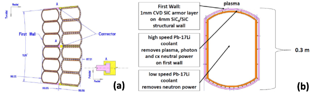
Figure 4. (a) Cross-section of ARIES-AT outboard blanket segment. (b) Cross-section of ARIES-AT outboard blanket module with SiC first wall. Dimensions in m [6, 51]. The PbLi coolant will be at ∼1000 °C, while the plasma-wetted surfaces will be hotter. Reprinted from [6], Copyright (2006), with permission from Elsevier.
Download figure:
Standard image High-resolution imageThe use of lower temperature coolants for the targets and main walls, e.g. 600 °C, as for the Flibe coolant called for in the ARC pilot plant design [22], does not preclude the surfaces internal to the vessel being significantly hotter: optimal heat management design could in principle exploit the power fluxes from the plasma onto the targets, ∼1–15 MW m−2, and main walls, ∼1 MW m−2, to achieve the required temperature gradients across the thickness of the target and wall armor.
US fusion will be in a position to exploit the advantages of low-Z material for armor and surface conditioning starting from the first actively-cooled DT device since it appears unlikely that the US will use water-cooling even for the first generation of reactors or for a pilot plant, owing to operational issues and low thermal conversion efficiency: 'in the United States, water has not been chosen as a fusion power core coolant for decades' [54]. The blanket of the first generation European EFDA fusion power plant, model A, on the other hand, will use water coolant with an inlet/outlet temperature of 285 °C/325 °C [55], resulting in a plant efficiency of 31% compared with 60% for the advanced 700 °C/1100 °C EFDA model D. In the US ARIES-AT, the breeding coolant (Pb–17Li) is superheated to ∼1100 °C, leading to an overall thermal efficiency of ∼59% [51]. US plans call for high temperature coolants including helium, liquid metals (e.g. Li and PbLi eutectic) and molten salts (e.g. Flibe and Flinabe) [54], which can enable conditions where tritium-retention in low-Z co-deposits will not be the major issue that it is at water-coolant temperatures. These coolants will, however, require significant development effort compared to water cooling.
As noted earlier, tritium-retention was the principal reason for the decision to not use graphite for the targets in the water-cooled ITER where the divertor cannot be baked above a few 100 °C, see e.g. [63]. However, based on measurements from JT-60U, figure 3(b), it is estimated that even a small increase in operating temperature would reduce the T-inventory in an all-carbon ITER-like tokamak by an order of magnitude or more, figure 3(c) [58–61].
It has long been thought that hydrogenic retention in carbon co-deposits is a non-saturable retention process, see e.g. 'The co-deposited layer has an almost limitless ability to store hydrogen isotopes in a carbon lined fusion device' [65]. While this has been well established to be the case for C co-deposits held at room temperature and pressure, more recently Tore Supra researchers discovered that carbon co-deposits formed in that tokamak and held under vacuum, naturally outgas their D content in 2–3 years even at the slightly elevated temperature of 120 °C [66], conditions that the ITER divertor will experience; thus, once in operation for extended periods at ∼continuously elevated vessel temperature, ITER's ∼steady-state tritium inventory could be significantly smaller than current projections. Further studies are needed to confirm this important finding.
Since most of the low-Z slag, together with any co-deposited tritium, would be continuously removed from the vessel, the T/C etc ratios in the slag would not be a critical issue; it is nevertheless a matter of importance since it is essential to recover as much tritium as possible. The present database for D(T)/C ratios in co-deposits is seriously inadequate, see figure 3(d) reproduced from [62, 63], showing that the data extend to only 600 °C; the database also needs to include the full range of co-deposit morphologies. Lab exposure facilities such as MAGNUM-PSI and MPEX are needed to extend the temperature range to at least 1200 °C and should include the effect of impurities. Similar data are needed for SiC, etc. Neutron damage may not be important for deposited material, but this needs to be experimentally investigated.
Silicon carbide has long been identified as a promising low-Z refractory material for fusion reactors as a structural material since it is highly resistant to neutron-damage [43–50, 67–72]. Although it has been less assessed with regard to its use as a plasma-facing material compatible with good plasma performance, SiC is considered to be promising for this application as well [27, 28, 47, 73–75]:
'The potential applications of SiC/SiC composites currently considered for the in-vessel components of magnetic confinement fusion devices may be classified into three categories: blanket structures including the first wall (FW), flow channel inserts (FCI) for the liquid metal (LM) blankets, and plasma-facing components (PFC's). However, there are currently no relatively mature PFC concepts that assume the use of ceramic matrix composites (CMCs), despite the favorable compatibility of the tungsten–SiC system (in terms of thermal expansion, joining technology, and operating temperature window) and CMC's likely adequacy as materials for certain helium-cooled PFC parts with radiatively-cooled, high-temperature surfaces in more aggressive PFC concepts' [47].
Recent developments have further enhanced the attractiveness of SiC for fusion application, in particular with regard to improved power handling capability. NASA has developed SiC fibers and SiC/SiC ceramic matrix composites (CMCs) that can be used in high temperature, high power load applications, such as hot components in gas turbine engines at up to 1500 °C: 'the CMC properties offer significant benefits in comparison to other options, including metallic superalloys, monolithic ceramics, carbon fiber composites and oxide/oxide ceramic composites' [68]. SiC CMCs are projected to ultimately achieve a thermal conductivity of ∼30 W m K−1 at 1000 °C [69], which would be comparable to Inconel X-750 at 750 °C.
The ARIES-AT reactor design calls for a SiC main wall: 'the first wall consists of a 4 mm SiCf/SiC structural wall on which a 1 mm Chemical Vapor Deposited (CVD) SiC armor layer is deposited', p 84 of [6, 51], see figure 4.
The ARIES-AT reactor design thus provides an illustration of an important aspect of the solution proposed here for solid PFC materials in pilot plants and reactors, namely thin, low-Z, ceramic armor on the main wall. The ARIES-AT designers did not, however, consider wall erosion, handling copious armor slag, refurbishing the armor, or ∼continuous surface conditioning.
The importance of reduced activation as a critical aspect of materials choice was brought to the fore in the 1980s:
'Structural materials research initially focused on conventional alloys such as Ti-modified austenitic stainless steel, but a watershed development in the early 1980s was a USA panel assessment that reduced-activation materials should be an essential criterion for selecting candidate structural materials (i.e., significantly lower long-term induced radioactivity, hands-on maintenance doses, and radiation release during accident scenarios). The importance of using reduced activation materials for fusion was subsequently re-emphasized in a senior panel evaluation [76] and was broadly adopted following two International Energy Agency workshops in 1989 and 1991' [69].
This underlines an important advantage of employing low-Z ceramics such as C and SiC for pilot plant and reactor first wall and blanket applications and has positive implications as well for the use of low-Z ∼continuous powder dropping for surface conditioning. The radioactive decay (cooling) time of various candidate plasma facing materials are compared in figure 5 [70] where the authors note: 'from the viewpoint of the surface dose rate, light elements such as C, Si and Be are the most preferred'. Because of the high flow-through rates of low-Z slag, reduced activation will be particularly important for the cladding material, potentially more critical than for the structural material with its relatively longer lifetime in the reactor.
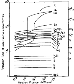
Figure 5. The cooling time of potential first wall materials required to reach 2.5 mrem hr−1 activation as a function of neutron fluence. Reprinted from [70], Copyright (1989), with permission from Elsevier.
Download figure:
Standard image High-resolution image5. A potential operating scenario for pilot plants and reactors using thin non-metallic low-Z refractory wall claddings
A variety of operating scenarios for pilot plants and reactors may be possible that employ ceramic low-Z refractories as the PFC material in direct contact with the plasma. No attempt is made here to identify the range of possibilities, instead one possible example is briefly described based on regularly replenished, thin carbon-based claddings of the main vessel wall.
Stoneham et al [77] have identified new carbon-based materials used as coatings to be one of the most promising solutions to the fusion PFC problem:
'There are three main avenues proposed in this work for designing materials for fusion power plant: new carbon-based materials as coatings, tailored alloys, and innovative composites designed to separate functionality through its components.
(a) Carbon coatings with mixtures of sp3 and sp2 bonding have good and controllable thermal and mechanical properties. They are likely to have resistance to radiation damage and physical erosion...' [77].
A possible operating scenario for pilot plants and reactors is described in the following. Since the database required for quantitative estimates is comparatively complete for carbon it has been used here for illustration; however, it seems possible that much of the following applies to other ceramic low-Z refractories such as SiC, however this needs to be established.
- (a)The divertor would be operated so that both targets are either detached or partially enough detached that the inflow of low-Z material from the walls puts the entire divertor into a state of net deposition [29, 36]. For single-null magnetic configurations, operation with reversed field (ion
 -drift away from the divertor) helps to achieve detachment of both divertors. Even for attached conditions, operation with reversed field in JET resulted in the migration of eroded wall material into both divertors [78] (whereas with standard field direction and an attached outer divertor, the migration was to the detached inner divertor only). Operation in reversed field is favorable to a number of high performance modes such as the AT, Advanced Tokamak [79], and the I-mode [80].
 - (b)With the entire divertor in a state of net deposition, the problem would not be target erosion-wear, but the opposite, as noted above, namely the need to regularly clear the PFC slag off the targets. Most of the wall-eroded carbon in the JET DTE1 campaign (along with 96% of the tritium that was retained in the vessel) ended up out of harm's way, as exfoliated co-deposit debris at the bottom of the vessel, below the water-cooled louvers located in the inner pump duct entrance [7, 8], see figure 8. In contrast with the exfoliated carbon deposits on the Tore Supra limiter, which caused frequent UFOs and disruptions [38, 39], the exfoliating carbon slag in JET DTE1 did not cause any operating problems. The reason for this critical difference is poorly understood and calls for more thorough experimental investigation; see the discussion below.
- (c)Thin, mm order, low-Z claddings on the main vessel walls would ideally be refurbished in situ. Starting in the 1980s, extremely thin coatings, <1 μm, have been created in situ on tokamak internal surfaces, using carbonization, boronization, siliconization, etc [10, 41, 42, 81]. Nevertheless, it will be a substantial challenge for coating technology and robotics to develop low-Z cladding methods that could be used in situ, to quickly create well-adhered mm thick layers, while not depositing too much material where not wanted, e.g. in tile gaps. Fortunately for fusion energy development, coating technology is a very large commercial activity driven and funded by major non-fusion industrial/commercial applications; it seems likely that in the future highly sophisticated in situ coating technology will be available for exploitation by fusion. While it is clearly preferable to avoid depositing coating material where not wanted, achieving that does not constitute an additional constraint since the high erosion rate of the wall—regardless of the material used in a DT tokamak—will tend to deposit PFC material almost everywhere, including in tile gaps. Powder dropping of low-Z material into operating plasmas for surface conditioning will do similarly. Therefore, as well as learning how to deposit new material in situ, it will be essential to learn how to remove it from where it is not wanted. As already noted, it is not evident that this can be achieved in situ for solid metals, while for the non-metallic refractories such as SiC it needs to be demonstrated that deposits in unwanted locations can be removed in situ without undesirable side-effects. For carbon, oxygen (O2, O3, O-plasma) baking is extremely effective for removing slag, particularly at elevated temperatures [82], and for Si etching it may be possible to use atomic H and F. The DIII-D tokamak has been O2-baked on two occasions [83]; it was found that: (1) laboratory measurements on the release of deuterium from tokamak codeposits by oxidation were duplicated in the tokamak environment, (2) no internal tokamak components or systems were adversely affected by the oxidation and (3) the recovery of plasma performance following oxidation was similar to that following regular torus openings.
- (d)It will be necessary to arrange for the cladding to be replaced before its function is compromised by neutron damage. For a wall fusion (neutron) power loading of 3 MW m−2 the damage rate for carbon is expected to be ∼40 dpa yr−1 [84]. It is not clear what the dpa limit is for a thin carbon cladding. The usual damage limit is considered to be 10–20 dpa [85]; however, that is for high-quality pitch-based fiber composites and for applications where the structural functionality of the carbon has to be maintained, neither of which would apply to a thin carbon cladding. Typically, present coating methods produce a poorly graphitized carbon where the lifetime is expected to be ∼20–40 dpa [85]. It is essential that the cladding remains adhered to the substrate and in good thermal contact with it. The cladding will be at high temperature, ∼1000 °C, and therefore there will be significant annealing of the neutron damage. Thermal conductivity will degrade with neutron exposure, however, wall (plasma) power loads will be relatively low, ∼1 MW m−2, and the temperature drop across a ∼1 mm carbon layer will be small. In fact, it is advantageous that the front surface be as hot as possible, short of causing damage, in order to suppress tritium retention. Assuming ∼20–40 dpa lifetime and 3 MW m−2 (neutron) wall loading [6], a carbon cladding would have to be refurbished every ∼6–12 months. The databases for thin coatings of other low-Z ceramics need to be generated; based on the well-established resistance of SiC to neutron damage, thin coatings of SiC may also be significantly more robust than for carbon.
- (e)For an area of 1000 m2 for the main wall of a DT tokamak and the removal rates estimated in table 1, the average wall erosion rate would be ∼2 mm yr−1 for B and C and ∼8 mm yr−1 for Si, just due to c-x neutral sputtering alone. In that case, the average thickness of low-Z cladding would have to be a few mm if it is planned that the cladding be removed by the operating plasma itself. This could be an acceptably thin low-Z barrier from the viewpoint of tritium breeding.
- (f)Other operating scenarios also need to be assessed. The state of deep divertor detachment, where both the inner and outer targets are in a state of net deposition across their entire surfaces, may not be compatible with required levels of He pumping. It is for this reason that the ITER design calls for only partial detachment of the outer divertor, where only the region at/near the outer strike point is strongly detached; further away along the target the plasma is attached with Tet ∼a few tens eV while the ion flux density is much lower than near the strike point. Since ITER is not a pilot plant or reactor, the resulting slow rate of net erosion at the far-target is probably acceptable; however, that will not be the case for pilot plants and reactors. As discussed earlier, continuous powder dropping of low-Z surface conditioning material into tokamak operating plasmas could be used to refurbish plasma-wetted surfaces, not only at the main wall, but throughout the vessel, including far-target surfaces which net-erode relatively slowly. Low-Z impurity seeding into the termination phase may also help suppress runaway electrons and reduce the risk of ramp-down disruptions. Localized refurbishment methods should also be explored: it has been experimentally demonstrated that injection of low-Z gas can be used to create protective coatings in the vicinity of the injection location: small amounts of CH4 injected near a Mo surface on the divertor target in DIII-D reduced the Mo erosion rate to below measurable levels [86]. At atmospheric pressure and dwell times <50 s, methane would not thermally decompose in feed lines below 900 °C [87]. More promising, however, is that for such locations: C, Si, B, etc powders could be locally injected using a D2 gas flow through tile-gaps at the specific target locations where net erosion would otherwise occur, injected at a rate adjusted to compensate for the local net erosion rate. Research and development of this promising technique for in situ surface coating will be required for localized applications. In the final analysis, optimization will require fine-adjustment, established empirically for the specific reactor design and operating condition, i.e. by 'tweaking'.

The use of thin, replaceable solid tiles is also a potential option: advances in autonomous robotics could make their installation and replacement compatible with the operational constraints of pilot plants and reactors. R&D efforts on robotics are financed by an industry that is doubling in size every few years: world-wide expenditures on robotics and related services are projected to be $210 billion in 2022, up from $116 billion in 2019 [88]. By the time that fusion will be in need of autonomous robots, it seems likely that they will be highly dexterous, fast and inexpensive—potentially resulting in a radical transformation of the problem of refurbishment of plasma facing materials in DT tokamaks, and possibly for some neutron-damaged structural components as well.
Recent advances in high temperature superconductors (HTSCs) have opened up the option for pilot plants and reactors to use jointed magnets, e.g. demountable (openable) magnets. This would in turn make possible greatly simplified designs where the entire vacuum vessel, including the main walls and divertor, would be a non-lifetime component that would, as a single, monolithic, pre-fabricated, structurally-strong, highly-aligned, and quickly replaceable unit, be lifted in and out (vertical lift) of an immersion blanket tank, see the ARC pilot plant example in figure 6 [22]. The worn-out wall cladding could be replaced along with the rest of the internal structure, and any residual tritium scavenged.

Figure 6. ARC: a compact, high-field, fusion nuclear science facility and demonstration pilot plant with demountable magnets [22]. The vacuum vessel, including the main wall cladding, would be a single replaceable non-lifetime component, quickly lifted in and out of an immersion blanket container. Reprinted from [22], Copyright (2015), with permission from Elsevier.
Download figure:
Standard image High-resolution imageUsing present technology, the replacement/refurbishment of PFC claddings approximately yearly would involve unacceptable down time of pilot plants and reactors. However, it seems likely that the continuing rapid evolution of HTSCs, autonomous robotics, thin coating technology, and 3D-printing—each heavily funded by major non-fusion 'deep-pocket' applications—will be transformative for fusion and may provide solutions for adequately rapid replacement/refurbishment of PFC claddings for pilot plants and reactors. It is therefore appropriate that near term fusion R&D efforts focus on the problems that will fall solely on the world fusion effort itself to solve. We consider such required research in the companion paper [9], part B.
As already noted, the effective thermal conduction of the main wall armor could be designed to result in very high temperature, say 1000 °C, on the plasma side, independent in principle on the temperature of the blanket coolant, by exploiting the photon and c-x neutral power load of order 1 MW m−2. The targets themselves are naturally very hot due to plasma power loading. Thus, the entire internal structure of a DT tokamak could in principle be operated at sufficiently high temperature that little tritium would be retained in the vessel. For commercial reactors to be able to use blanket coolants such as liquid LiPb at ∼1000 °C, significant time and effort will be required to develop the technology for handling such coolants. Pilot plants may need to use more available coolants such as Flibe, as called for in the ARC pilot plant design [22], which are limited to about 600 °C; however, as already noted, the effective thermal conduction of the main wall armor of the pilot plant could in principle be designed to result in a 1000 °C plasma-facing surface by exploiting the photon and c-x neutral power load.
6. Physics questions
Are the concepts described in the foregoing sections viable? Unfortunately, most of the information required to make an adequately informed assessment is not available today. The following is a partial list of the major physics questions that will need to be answered in order to assess the viability of the approach proposed here.
- (a)For each low-Z element and compound of potential interest for protection of the main wall, what is the gross erosion rate in present MFE devices due to (1) scrape-off layer (SOL) ions, (2) fast ions lost from the confined plasma, and (3) c-x neutrals, and how do these scale to pilot plants and reactors? Rates are needed as a function of wall temperature, size of the wall gap (separatrix to solid structures), degree of divertor detachment, fraction of DT recycling neutrals that escape from the divertor, and the ratio of DT recycling at the main walls to that occurring in the divertor, i.e. the magnitude of main chamber recycling (MCR).
- (b)What is the controlling physics of MCR occurring in present MFE devices and how does it scale to pilot plants and reactor tokamaks? Present research efforts on cross-field blobby transport in the far-SOL need to be further expanded. It is necessary to develop as thorough an understanding of cross-field transport physics in the far-SOL and loads on the walls, as is already being vigorously and successfully pursued for the near-SOL where it is strongly motivated by the issue of power loads on the targets.
- (c)What fraction of (1) sputtered wall material and (2) the low-Z material resulting from powder dropping, gets transported to the divertor(s)? How does that depend on the element/compound involved? How does it depend on heating power, Greenwald fraction, confinement mode, degree of detachment of each divertor, B-field magnitude and direction, pumping rate, fueling method and rate, magnitude of ballooning transport, momentum-coupling between SOL and confined plasmas, etc?
- (d)For what conditions does the low-Z slag reaching the divertor cause (not cause) problems such as UFO-disruptions, unsafe dust levels, etc? How does this depend on the element/compound involved? For conditions that cause problems, can practical solutions be found?
- (e)What was the controlling physics/chemistry that occurred in the JET DTE1 campaign, which resulted in the wall carbon slag not accumulating on the inner target, but migrating into the adjacent pumping cavity where it accumulated in regions out of contact with the plasma? Was this a natural process or was it due to the strike-point sweeping that was performed? If this process can be externally controlled, how to optimize it? How do the controlling processes depend on the low-Z element/compound involved? How do they depend on the target structural material, tile shaping and temperature?
- (f)For the low-Z slag that remains in the main chamber: where does it accumulate? Under what conditions does this result (not result) in problems? For problem cases, can practical solutions be found? Can the shape and deployment of the protection limiters in the main chamber and of the main-wall itself, be optimized to help facilitate slag management?
- (g)Can chemistry, such as oxygen baking, be used to remove residual low-Z deposits in the main part of the vessel without causing collateral damage? In situ refurbishment of claddings may deposit material where not wanted; can chemistry be used to safely remove such material?
- (h)What is the dust size distribution associated with (1) sputtering of claddings, (2) powder dropping, (3) in situ refurbishment of claddings? How does it depend on the element/compound involved? How does it depend on the operating conditions?
- (i)Databases are needed for each low-Z element/compound of interest for: (1) sputtering yield; (2) tritium retention due to (i) implantation, and (ii) co-deposition; (3) maximum thickness of deposit layers before exfoliation; (4) neutron-damage lifetimes of thin claddings; each property as a function of material temperature for fusion-relevant neutron damage.
7. Summary and conclusions
Current estimates of charge-exchange neutral fluxes to the walls of pilot plants and reactors indicate that a fundamental paradigm shift appears to be required in planning to deal with the large volumes of eroded and redeposited solid wall materials that have the potential to seriously compromise the operability and safety of high duty cycle DT devices starting with pilot plants. It appears that the materials of solid plasma facing components in pilot plants and reactors will have to be treated as consumable and flow-through solid substances, like the linings of car brakes.
Non-metallic, refractory, low-Z ceramics, used as an in situ replenished, thin cladding on a substrate which is resistant to neutron damage, could provide a potential PFC solution for MFE DT devices of all configurations. Graphite and most other low-Z ceramics are solid, non-melting, refractories, yet many of these materials can be conveniently introduced into a vacuum vessel as a gas for in situ coating by chemical or physical vapor deposition or plasma assisted CVD. Carbon and other low-Z elements are quite satisfactory as a plasma-facing material regarding the effect on the plasma: they radiate well in the edge plasma and are tolerable at relatively high concentrations in the central plasma. Some low-Z ceramics such as graphite, are unsuitable as a structural material for prolonged exposure to neutrons due to swelling; however, as a thin (order mm) cladding, the time between refurbishments could be made less than the time to accumulate levels of neutron damage, which would compromise the integrity of the cladding; SiC, on the other hand, is particularly resistant to neutron-damage. At reactor-relevant coolant temperatures ∼600 °C–1000 °C, where the surface temperatures are yet hotter, there is very little tritium retention in carbon; it seems possible that other low-Z materials will behave similarly, however the database is sparse. The quite possibly incompatible requirements that a PFC material be satisfactory with regard to both plasma and neutron interactions would therefore be dealt with by a 'separation of function' design: the substrate need not be plasma-compatible, which opens up more options. Because the low-Z layer on the main walls (eroded mainly by c-x neutrals) would be frequently refurbished, it would be thin, of order mm, which is important for tritium breeding and heat transfer. It would appear to be feasible to refurbish plasma-eroded layers, e.g. antennae and remote parts of the targets, during regular plasma operation of reactors using ∼continuous powder dropping to globally inject C, B, Si, etc, or to locally inject CH4, SiH4, B2H6, etc, gas or to locally inject low-Z powder in D2 carrier-gas, into the plasma at tile gaps adjacent to regions of net erosion. The divertor would be operated in detached or semi-detached conditions so that both inner and outer targets would be arranged to be in a state of net deposition due to transfer of low-Z material from the main walls and/or from powder injection used for surface conditioning. Selected areas near the divertor out of direct plasma contact could be used to collect and sequester the low-Z deposited slag material for eventual removal from the DT device. During its sequestration within the vacuum vessel, the collected debris could be baked by externally-controlled heaters to thermally desorb residual tritium co-deposited in the debris, without requiring vessel entry or breaking vacuum.
While coverage of the targets with wall material will pose major challenges for pilot plants and reactors, it will also bring an important potential benefit: since the plasma will only 'see' wall PFC material, options are increased for the choice of the target armor material: it need not be plasma-compatible, nor have low potential for co-deposition retention of tritium, etc.
Powder droppers provide a unique opportunity to study the management of low-Z slag in all presently operating tokamaks regardless of the material used for their protection tiles. For dedicated and controlled experiments, significant amounts of material could be injected in a short time in order to create thick enough layers to be able to carry out useful studies. By contrast, natural erosion rates are too small to create thick deposits quickly, and in any case, this could only be done in tokamaks having low-Z protection tiles.
Using present technology, the replacement/refurbishment of PFC claddings approximately yearly would involve unacceptable down time of pilot plants and reactors. However, it seems likely that the continuing rapid evolution of HTSCs, autonomous robotics, thin coating technology and 3D-printing—each heavily funded by major non-fusion 'deep-pocket' applications—will be transformative for fusion and could provide solutions for adequately rapid replacement/refurbishment of PFC claddings for fusion pilot plants and reactors.
The effective thermal conduction of the main wall armor could be designed to result in very high temperature, e.g. 1000 °C, on the plasma side, independent in principle on the temperature of the blanket coolant, by exploiting the photon and c-x neutral power load of order 1 MW m−2. The targets themselves are naturally very hot due to plasma power loading. Thus, the entire internal structure of a DT tokamak could in principle be operated at sufficiently high temperature that little tritium would be retained in the vessel. For commercial reactors to be able to use blanket coolants such as liquid LiPb at ∼1000 °C, significant time and effort will be required to develop the technology for handling such coolants. Pilot plants may need to use more available coolants such as Flibe, as called for in ARC pilot plant design [22], which are limited to about 600 °C; however, in principle, the effective thermal conduction of the main wall armor of the pilot plant could be designed to result in a 1000 °C plasma-facing surface by exploiting the photon and c-x neutral power load on the main walls.
US fusion will be able to exploit the advantages of low-Z material for armor and surface conditioning starting from the first actively-cooled DT device since it appears unlikely that the US will use water-cooling even for the first generation of reactors or for a pilot plant, owing to operational issues and low thermal conversion efficiency: 'in the United States, water has not been chosen as a fusion power core coolant for decades' [54]. US plans call for high temperature coolants including helium and liquid metals [54], which can enable conditions where the overall thermal efficiency can reach ∼60% and tritium-retention in low-Z co-deposits need not be the major issue that it is at water-coolant temperatures.
The development of HTSC magnets has the potential to be particularly transformative for fusion pilot plants and reactors, enabling quick replacement of the entire internal structure. Openable HTSC magnets will enable vertical-lifting of the entire internal structure as a monolithic unit. The removed structure would be baked at >1000 °C to remove any residual tritium. Due to the low activation of low-Z elements like C and Si, disposal of any waste material should in principle be manageable. Frequent enough replacement may permit use of attractive structural materials otherwise not usable because of their low neutron-damage-resistance.
Considering the material of solid-surface PFCs in pilot plants and reactors as a consumable, flow-through substance is such a fundamental paradigm shift that it has transformative implications for virtually all aspects of DT tokamak design pertaining to the interior of the vessel, as well as for a number of critical ex-vessel aspects such as tritium recovery and processing. Treating the solid-surface PFC material as a flow-through consumable substance will have to be allowed for from the earliest stages of the planning and design of pilot plants and reactors—as something so completely nonstandard as to not be realistically deferrable. It is not likely to be something that can safely be assumed fusion development will somehow manage to sort out on the fly when the time comes.
When it can be reasonably anticipated that a particular road is going to end up as a dead-end then clearly it should not be a path that is started down. Absolute show-stoppers need to be identified as early as possible. For fusion pilot plants and reactors, is the PFC slag problem an absolute show-stopper for low-Z, non-metallic PFC-cladding? For metal PFCs? For all solid PFCs? Potentially even a small research effort at an early stage could answer this question adequately enough to save a great deal of wasted time, effort and money.
Acknowledgments
This manuscript has been authored by UT-Battelle, LLC, under contract DE-AC05-00OR22725 with the US Department of Energy (DOE). This material is also based upon work supported by the US Department of Energy, Office of Science, Office of Fusion Energy Sciences, using the DIII-D National Fusion Facility, a DOE Office of Science user facility, under Awards DE-FC02-04ER54698, DE-AC05-00OR22725, DE-SC0019256, DE-FG02-07ER54917, and DE-NA0003525; and by Princeton Plasma Physics Laboratory under contract DE-AC02-09CH11466.
Data availability statement
All data that support the findings of this study are included within the article (and any supplementary files).
Disclaimer
This report was prepared as an account of work sponsored by an agency of the United States Government. Neither the United States Government nor any agency thereof, nor any of their employees, makes any warranty, express or implied, or assumes any legal liability or responsibility for the accuracy, completeness, or usefulness of any information, apparatus, product, or process disclosed, or represents that its use would not infringe privately owned rights. Reference herein to any specific commercial product, process, or service by trade name, trademark, manufacturer, or otherwise does not necessarily constitute or imply its endorsement, recommendation, or favoring by the United States Government or any agency thereof. The views and opinions of authors expressed herein do not necessarily state or reflect those of the United States Government or any agency thereof.
Appendix A.: Basis of the rough estimates for the wall erosion rate in table 1.
The rough estimates in table 1 are based on the assumptions:
- (a)physical sputtering by mono-ergetic c-x neutral tritons only; <Ec-x> = 0.3 keV T0 assumed; EIRENE code calculations for ITER conditions report average c-x energies at the outer midplane (the most intensely bombarded location) of ∼0.6 keV, with 20% of the c-x atoms having >1 keV energy [35]. A value of 0.3 keV is assumed to provide a rough estimate for the poloidal average. It may be noted that the assumption of a mono-energetic incident species, as compared to a thermal distribution, makes little difference for all elements except W. For W, sputtering is significantly increased if a distribution of energies is assumed since for high-Z elements, impacting particles with above-average energy have a significantly higher sputtering yield than for the average energy.
- (b)Normal incidence sputtering yields [89] doubled to account for surface roughness: for (Be, B, C, Si, Fe, W), Yc-x = (0.083, 0.056, 0.035, 0.080, 0.10, 0.0048) (In the case of Si and Fe, where sputtering values for T are not available, an average of the D+ and He+ values is used.);
- (c)for a conservative estimate, no sputtering included for D0, He0 or any plasma-wall contact (ionic);
- (d)compared with physical sputtering, negligible chemical sputtering or radiation enhanced sublimation of C at reactor-relevant temperatures, of ∼600 °C < Twall < 1100 °C (see e.g. in [90, chapter 3]); ultimately fusion reactors will operate with coolant temperatures of ∼1000 °C in order to achieve high thermal efficiency. The plasma-wetted surfaces will be yet hotter. See section 4
- (e)assumed Pc-x = 0.05 PSOL [91, 92] thus where is Tc-x particle flux to walls, thus gross erosion rate = Yc-x
net erosion rate for the main wall. As noted in section 1, away from the divertor targets, the rate of net erosion is approximately the same as the rate of gross erosion, i.e. sputtering, since prompt local re-deposition is not effective due to long ionization distances at low plasma density.


Appendix B.: The effect of impurities on the DT burn condition,

The following is based on the analysis of Meade [93], Jensen et al [94], and Reiter et al [95]. Here it is assumed that:


Also that the He ions are doubly charged and that the other impurity ions have an average charge of  at temperature T:


From the above definitions it can be shown that:


Including possible beam-drive, DT plasma power balance gives:
where  is the energy confinement time,
  is the volumetric radiation power loss rate,
  is the plasma fusion power from thermal DT reactions,
  is the beam-plasma fusion power and
  is the power of the injected beam. Both
  and
and  correspond to the release of 17.6 MeV per reaction. Since only the 3.5 MeV
  -particle contributes to the plasma power balance, the total fusion power in equation (B12) is multiplied by 0.2:

where  = 17.6 MeV and
  is the DT fusion reaction rate.
From the above it can be shown that [94]:


For ignition, i.e. Q
 , then
  = 0 and A = 0.2. Jassby in figure 1 of [96] gives the values for
  for 200 keV D into a 100% T bulk plasma; for D into a 50:50 D-T bulk plasma the values of
  are smaller by a factor ∼0.5 [97]; for example, for Q = 5 and 200 keV D into a 50:50 D-T bulk plasma of temperature 10 (20) keV,
  ∼ 1.0 (1.2), thus A = 0.50 (0.53).
where  ,
,  and
and  are the radiative power coefficients:
The specifiable impurity parameters are  and
and  ; however,
  can be related to
  and
and  using equation (B11) and f =
  , see equation (B10), thus:
In the following,  ,
,  ,
,  and
and  are taken from OPEN-ADAS [98] for ensemble-averaged rates either for coronal equilibrium or for a collisional radiative estimate. The DT fusion reaction rate,
  is taken from [94, 99]. The Q-value for the beam, i.e.
  , is taken from figure 1 of [96]. Figure 1 in the main text gives the minimum value of
  (at T = 15 keV) required for ignition (
 = 0 and Q
 ) as a function of (non-He) impurity fraction, f, with a 5% concentration of core He. Figure B1 gives the minimum value of
  (at T = 15 keV) required for Q = 5 beam-driven fusion as a function of (non-He) impurity fraction, f, with a 5% concentration of core He.
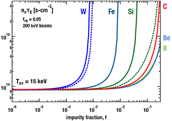
Figure B1. The minimum value of  (at T = 15 keV) required for Q = 5 beam-driven fusion as a function of (non-He) impurity fraction, f, with a 5% concentration of core He. The dashed lines assume coronal equilibrium; the solid lines assume a 10 ms dwell time for the impurities.
Download figure:
Standard image High-resolution image