

Abstract
This paper assesses the feasibility of using kilo-joule class laser systems to pre-ionise an air column enhancing the propagation of relativistic electron beams. In a vacuum a charged beam will always diverge. In a plasma it may focus depending on the degree of beam charge and current neutralisation. Beams diverge due to scattering, but this paper highlights a parameter regime where plasma focusing in a pre-formed plasma may allow propagation of ∼10 GeV electron beams over a distance ∼10 m. Central to this theory is the degree to which the background plasma acts to charge or current neutralise the electron beam. These effects are quantified in a reduced 2D model using relativistic kinetic plasma simulations. These demonstrate that charge neutralisation is sufficiently high, and current neutralisation sufficiently low, that the proposed scheme is viable. The key problem identified in this paper is the difficulty in forming a suitable ionised channel. The primary laser energy loss mechanism for the parameters chosen is through inverse bremsstrahlung, not air ionisation, and possible ways to mitigate these losses are discussed.
Export citation and abstract BibTeX RIS

Original content from this work may be used under the terms of the Creative Commons Attribution 4.0 license. Any further distribution of this work must maintain attribution to the author(s) and the title of the work, journal citation and DOI.
1. Overview
In this paper, we will investigate the propagation of a relativistic electron beam in a plasma column created in air by a powerful laser beam. In the first part of this work, we investigate the creation of a column of plasma in air by a long laser pulse via the ionisation of air (nitrogen) molecules. In the second part, we investigate the self-focusing of a relativistic electron beam inside this plasma column. Finally key assumptions in the theory of electron beam propagation are tested using a reduced model with 2D relativistic kinetic simulations.
The results can be summarised as follows. A laser beam with an energy 1 kJ and a duration of 2 ns can ionise a plasma column in air of 1 mm2 cross section and up to ∼1 m in length provided that ionisation is the only laser energy loss mechanism. The laser wavelength needs to be 'third harmonic' (351 nm assuming an Nd:Glass laser) so the laser pulse's group speed is not too far below c (0.997c in fact). The electron beam, travelling at speed c, will start in the tail end of the ionising laser beam, co-propagate with it, and slowly overtake it over a scale of ∼c  m, i.e. over 10 m the electron beam will remain in the laser pulse. Since the electron beam finds itself inside the ionising laser beam at all times, it is guaranteed that it will always be travelling in plasma. These estimates ignore the IB heating of the laser produced plasma and for these parameters, chosen to match current state-of-art high-power laser systems, IB losses would limit laser propagation to just ∼1 m. Possible ways to mitigate these limitations are discussed in the conclusions.
The plasma will have two effects on the divergence of the electron beam: (i) collisions with the nuclei of nitrogen atoms will cause the electron beam to diverge, while (ii) self-focusing due to interactions with the plasma electrons will cause the electron beam to be refocused. Of these two effects, the first will always dominate over long distances. However, over short and intermediate distances (a few 100 m), the second effect can be used to limit the divergence angle of the electron beam. For example: an electron bunch with 1 nano-Coulomb of charge and 100 MeV energy, can be confined to a divergence angle of θ = 2 × 10⁻⁶ over a distance of 250 m if a plasma channel that long could be generated. Over this distance, the transverse beam radius will increase by only 0.5 mm. This estimation assumes that the electron beam is fully charge neutralised by the background plasma and that the background plasma does not reduce the electron beam current density. These distances suggest beam divergence would not be an issue over 10 m.
2. Motivation
Particle beam physics rarely needs to be studied outside of high vacuum conditions. However, laser wakefield acceleration (LWFA) is able to achieve accelerating gradients over 1000 times greater than conventional RF-based accelerators, making table-top particle beam sources possible. These LWFA sources may lead to novel applications but require a better understanding of particle beam propagation through air at atmospheric pressure. Particle beams generated via LWFA are of particular interest because their high spatiotemporal charge density may give rise to nonlinear propagation when interacting with atmospheric pressure air.
One such application is through-barrier x-ray backscatter imaging from a pulsed laser system [1]. Typically, conventional x-ray backscatter systems generate the x-rays at source and, due to Klein–Nishina cross sections [2], the resulting backscattered x-rays are limited to energies no greater than ∼0.25 MeV. Additionally, the difficulty in focussing x-rays results in transmitted and received inverse square law losses associated with these conventional systems. One of the main advantages of an x-ray backscatter system using a LWFA source is that the x-rays are not required to be transmitted, rather they can be generated at, or close to, the target due to bremsstrahlung of the transmitted electrons when interacting with the target/barrier material. Therefore the inverse square law limitations of transmitted x-rays can be largely overcome by transmission of a low emittance LWFA electron beam. This means that performance is far more dependent on the distance between the detector and object to be imaged, a substantial improvement on current x-ray tube based systems. However, it is also critical to maintain a collimated beam of electrons for this advantage to be maximised.
For electron beams, it is well known that a dominant scattering mechanism that leads to a reduction in beam charge density with range are interactions between the beam electrons and air during propagation. It is therefore of interest to investigate methods which could reduce this effect. One such possible method is electron beam propagation through a pre-ionised channel of air, which is the focus of this paper. In particular this paper presents a feasibility study of using modern kJ class laser systems, as would be used for the LWFA, to also pre-ionise air prior to the injection of the electron beam.
3. Ionisation of air by a long laser beam
First, we study the ionisation of a column of air (mainly nitrogen) by an intense laser beam. The molecular density of air at sea level and ambient temperature (of order 300 K) is ∼2 × 10¹⁹ per cubic centimetre. While ionisation of the first electron of nitrogen takes less than 10 eV, ionisation of the fifth electron takes almost 100 eV. Given the laser intensities we aim to use, we assume that ionisation by the laser's fields will yield one electron per N atom. After ionisation, this can yield as many as  electrons per cm3.
The first challenge to overcome is the rapid recombination of the air after it has been ionised by the driving laser beam. For most gases, the recombination coefficient is α ∼ (1–3) × 10−7 cm3 s−1 [3]. The recombination rate is then αne ∼(1–6) × 1013 per second, giving a recombination time below 0.1 ps, and the recombination distance is below 30 µm. This means that at this temperature we cannot have the electron beam following the laser pulse: the plasma will recombine so rapidly after passage of the laser pulse that any trailing electron beam will not see plasma but neutral nitrogen atoms. Heating of the plasma above 300 K by inverse bremsstrahlung (IB) will reduce the recombination rate and relax this restriction and it may be possible for the electron beam to trail behind the laser pulse but this is not considered here.
For comparison: in a tokamak, the plasma electron density is only 1014 per cm3, or  per second, much lower because of the lower plasma density. In the SLAC 'energy doubling experiment' (plasma wave driven by a 42 GeV electron beam, see Blumenfeld et al [4]), the plasma bubble was only 100 µm long, so the lower bound on the recombination time was only 0.3 ps, which can be accommodated by lithium vapour at moderate density. It is the specific combination of a high plasma density and the need to maintain the plasma over a longer distance (and thus postpone recombination for as long as possible) that complicates matters.
A second issue is the difference in speed between the electron beam and the ionising laser pulse. An electron beam at 100 MeV satisfies v/c = 0.99987 ≈ 1. (For higher electron energies, this number will move even closer to 1.) Laser light with a vacuum wavelength of ∼1 µm when in plasma with an electron density of  electrons per cm3 (or 5% of the critical density) satisfies v/c ≈ 0.97. Thus, we have to accept that the laser pulse will propagate 3% more slowly than the electron beam, which is significant. Using third harmonic light (351 nm), gives v/c ≈ 0.997, i.e. only 0.3% difference, which is already an improvement. In this case the background plasma would be only 0.5% of the critical density.
To solve both issues at the same time, we propose the following setup. A long laser beam (at least 2 ns) is sent ahead of the electron beam, to ionise the plasma. While the plasma will recombine very quickly after passage of the laser pulse, it will remain ionised within the laser pulse itself. The electron beam is then injected into the tail end of the laser beam. The electrons co-propagate within the laser pulse, and thus remain within the plasma created by the pulse. Assuming that the electrons travel 0.3% faster than the laser pulse (third harmonic, 351 nm), they will need 200 m of propagation to overtake the laser pulse. Thus for 10 m propagation the electron beam is sure to remain within the laser pulse.
The minimum laser power needed for ionisation of this configuration can be calculated as follows. The minimum intensity for ionisation is 1011 W cm−2. If we assume a spot area of 1 mm2, then we need 1 GW minimum power. Since the laser beam is ionising the air during propagation, its energy is slowly being drained. The two main pathways for laser beam depletion are ionisation of air particles and IB heating of the (free) plasma electrons. The energy needed to ionise a column of air can be calculated as follows. Per ionisation, we need 10 eV of energy. Assume 5 × 10¹⁹ ionisations per cc, and a plasma column of 1 mm2 cross section and 10 m in length, i.e. 10 cm3 in total. This will need 80 J of laser energy per cm3 of air, or 0.8 kJ of laser energy in total. Direct bremsstrahlung emission of x-rays from plasma electrons has been shown to be a source of pair-production showers but are not included in the current analysis [5]. IB heating will deplete the laser beam even more than the ionisation. An upper limit of the ionised electron gas temperature can be simply estimated from the IB loss rate from the laser
where eL is the laser energy density and in S.I. units
where we have assumed singly ionised gas and ncr
is the critical plasma density for the laser. Assuming lnΛ = 10,  and a laser wavelength of 351 nm gives
  . Since the rate of loss of laser energy density equals the rate of increase of electron thermal energy density
  this gives
where  and Tf
are the initial and final temperatures due to a passing laser pulse with duration τp
. For simplicity, and to get an upper estimate for Tf
, we assume eL
is constant and set by a 1 kJ laser into a
and Tf
are the initial and final temperatures due to a passing laser pulse with duration τp
. For simplicity, and to get an upper estimate for Tf
, we assume eL
is constant and set by a 1 kJ laser into a  cross-section column which gives
  for
for  . Since this is an upper estimate we take the background plasma peak temperature order of magnitude to be ∼100 eV. This estimate is supported by previous modelling for experiments on Raman and Brillouin amplification [6–8]. Hence to heat the electrons from 10 cm3 of air to 100 eV, 8 kJ of laser energy is required. However, increasing the laser energy to 8 kJ would exacerbate the IB heating so here we assume a 1 kJ laser whose propagation distance would be restricted to 1 m due to IB. While a few kJ laser would be acceptable in a laboratory with proper shielding, interlocks, etc it can be a significant hazard when done outdoors. Although the design of the laser system and surrounding infrastructure is beyond the scope of this feasibility study paper, we conjecture that the laser requirements may well be met using the new DiPOLE technology [9, 10]. Thus, in order to produce and maintain a column of ionised air for long enough to guide the electron beam over 10 m or more, the amount of energy available in the laser beam for the ionisation and heating of the electron plasma is going to be the deciding factor.
To mitigate losses due to both ionisation and IB heating, we recommend that the intensity of the ionising laser beam does not much exceed 1013 W cm−2. A 1 kJ, 2 ns laser pulse into a cross-sectional area of 1 mm2 would, assuming uniform illumination, have an intensity of 5 × 10¹³ W cm−2. This has several advantages. (i) It limits the number of electrons liberated per atom, which in turn limits overall losses due to IB heating and ionisation. (ii) It also reduces the temperature where IB heating saturates. Radiation-hydrodynamic simulations show that the saturation temperature is around 200 eV for 1013 W cm−2 intensity, but jumps to 850 eV for 4 × 10¹⁴ W cm−2 intensity. (iii) A lower laser intensity reduces the transverse 'wiggle' of the electrons in the fast bunch when interacting with the laser field, and thus reduces the divergence of the beam electrons caused by this 'wiggle' (see below). (iv) Finally, the linear growth time of stimulated Raman scattering (SRS) of the laser, which would deplete the laser energy by scattering into EM waves and plasma oscillations, would be kept below 100 ps. While this is still many e-folding times for a 2 ns pulse SRS will saturate and for such laser systems the bursty behaviour of SRS often leads to a net loss of laser drive of less than 10% [11]. The SRS losses could also be reduced by the use of random phase plates as for example in Peyser et al [12]. In addition the back-scattered EM wave can still contribute to ionisation so, while needing further study, SRS is likely to be a minor energy drain from the laser drive. One way to reduce the laser intensity is to increase its duration (preferably not too much beyond the Rayleigh range to avoid issues with pulse self-focusing, see below). Using a longer laser pulse will also keep the eroding pulse front away from the electron beam throughout the interaction.
Divergence of the electron beam due to transverse motion in the fields of the ionising laser beam can be estimated as follows. For the laser pulse in plasma, we have k =  ω, where
  . The electrons move with speed ∼c, so the electric field they see equals
 ![$E ~ -\partial A/\partial t \sim \omega_0 a_0~\cos[ \omega_0(1-\epsilon) t ]$](https://content.cld.iop.org/journals/0741-3335/63/8/084009/revision2/ppcfac0b9dieqn13.gif) . We then find that the transverse momentum amplitude is given by
. We then find that the transverse momentum amplitude is given by  . We note that the bunch electrons see a lower frequency for the EM wave because they are not stationary but co-propagating with the EM wave; this leads to larger transverse excursions. For a laser intensity below 1014 W cm−2 at third harmonic, we find that
  ; for a plasma density of 5 × 10¹⁹ per cc we find that
  , so
, so  . Meanwhile, the longitudinal momentum for a 200 MeV electron beam is ∼390
  . Thus, the average deflection angle for the electrons when interacting with the laser beam is
  . Over 10 m longitudinal propagation, we can expect a transverse deviation of up to 8.5 mm. This could be larger than the residual divergence from the small-angle scattering off ions, so it is an important effect that needs to be taken into account.
In summary, we may have to make sure that the laser intensity surrounding the electron bunch is 'just enough' to keep the plasma ionised, so the background electron number density, the IB heating per background electron and the transverse motion of the bunch electrons in the laser's EM fields are all limited. Increasing the energy of the electron bunch will also help to reduce its transverse motion.
All the above estimates have been made under the assumption that the laser beam remains collimated throughout, so we have to ensure that this is indeed the case. The Rayleigh range for the laser beam is given by:  by symmetry about the focus the total length of focused beam is
  For R0 = 0.5 mm and λ = 351 nm, we have LR
∼ 4.4 m, which may not be enough. At such laser powers, we also need to consider the relativistic self-focusing of the laser beam (this is a separate effect, not directly related to the self-focusing of the accelerated electron bunch). Laser beam self-focusing in plasma follows from the competition between the natural divergence of a laser beam with a finite transverse diameter and intensity-dependent changes to the relativistic plasma frequency that cause the laser beam to converge. For a laser power
For R0 = 0.5 mm and λ = 351 nm, we have LR
∼ 4.4 m, which may not be enough. At such laser powers, we also need to consider the relativistic self-focusing of the laser beam (this is a separate effect, not directly related to the self-focusing of the accelerated electron bunch). Laser beam self-focusing in plasma follows from the competition between the natural divergence of a laser beam with a finite transverse diameter and intensity-dependent changes to the relativistic plasma frequency that cause the laser beam to converge. For a laser power  , where
  GW is the threshold power for laser self-focusing [13], the relativistic effects will be too weak to completely counteract the laser divergence. However, the divergence will be delayed and the laser beam will remain collimated over an 'effective Rayleigh range' of
  [13, 14]. For a laser power
  , the relativistic effects will prevail over the natural laser divergence, and the laser beam will self-focus over a typical focal length of
  [14]. For our case,
  , we find that
  GW, so a laser power of up to 3 TW will be below the self-focusing threshold. For the 0.5 TW system (1 kJ into 2 ns), the effective Rayleigh range will be
  , i.e. up to Lz
∼ 4.8 m extending the range over which the laser beam will remain collimated by only a small amount. The region outside of this Gaussian focus will have a lower laser intensity and hence reduced IB heating and lower ionisation fraction. Both of these may be beneficial to the effective length of the plasma channel.
, i.e. up to Lz
∼ 4.8 m extending the range over which the laser beam will remain collimated by only a small amount. The region outside of this Gaussian focus will have a lower laser intensity and hence reduced IB heating and lower ionisation fraction. Both of these may be beneficial to the effective length of the plasma channel.
There are important effects missing from the laser propagation and ionisation of air described above and out of the scope of the present analysis. The Kerr effect will likely tend to cause focusing of the front of the laser pulse and potentially its breakup into filaments. Previous work on short pulse (less than a pico-second) in the GW power range [15] found the Kerr effect responsible for the formation of localized plasma filaments 1 m in length, 100 micron in radius, and a temperature of just 1 eV. These parameters differ from those used here where a TW power laser is propagated for over a nano-second. Nonetheless this points to the importance of the Kerr effect and its interaction with diffraction and ionisation in any future work. The collapse of the laser pulse width will be arrested by increased ionisation combined with the de-focusing due to the generation of plasma. The present study is a feasibility study for electron beam propagation in a laser produced plasma channel in air. Later studies of this process, based on parameters identified in the work presented here, will have to deal with a comprehensive analysis of the dynamics of the laser propagation. At this stage we note that the typical laser beam widths considered here are of order millimeters while the electron beam widths are microns. Thus we expect that the electron beam will always be within a laser ionised channel but the precise ionisation state, and it is possible time dependence due to the competing non-linear focussing/defocussing effects, has not been determined. Purely for simplicity in this feasibility study we therefore assume a uniformly ionised steady laser produced plasma.
In summary, we have found that a laser pulse with 351 nm wavelength, 2 ns duration and 0.55 mm spot diameter, and 1 kJ of energy, could ionise a plasma column 10 m in length but that IB losses are likely to keep that down to of order one meter. This is pushing at the edges of available technology, but might well be conceivable using the latest (or future) DiPOLE [9, 10] technology.
4. Electron scattering in the atmosphere
The bane of electron beam propagation through the atmosphere over many metres is scattering off the atoms in the air. This can be modelled as follows. Using the scattering model proposed by Robinson et al [16], we have:
Here, na
is the ion density, Z the ionisation level of the ions, γme
and p are the electron energy and momentum respectively and lnΛ is the Coulomb logarithm for elastic electron-ion scattering. From this, we can estimate the growth in  over a distance L to be
  . Here, Γ is a function of the electron energy and the atmosphere properties. We can now define a 'scattering length' in terms of the length required to produce scatter equal to some critical angle θd
, i.e.
. Here, Γ is a function of the electron energy and the atmosphere properties. We can now define a 'scattering length' in terms of the length required to produce scatter equal to some critical angle θd
, i.e.  . Then, if we re-focus in the atmosphere we need to ensure that

where Ri is the initial bunch radius and θf is the half angle of refocusing. Put more concisely, we require that
For standard atmospheric conditions the actual limit on θf is shown in figure 1.

Figure 1. Plot of the limit imposed by scattering on the re-focusing half-angle in mrad as a function of initial (maximum) bunch radius Ri and electron energy relativistic γ factor.
Download figure:
Standard image High-resolution imageFigure 1 shows that we are limited to (typically) a few mrad in terms of the refocusing half-angle. Since this is largely an estimate, and we need to add a 'safety factor' onto this, we can see that the limit will quickly approach the typical divergence half-angles of most bunches. This in turn suggests that we will want to design a system that is close to symmetrical re-focusing. Note that although we are only considering elastic scattering from the nuclei, this is not a poor approximation: the cross-sections for collisional ionisation (for example) are very small and will not make an appreciable contribution.
5. Self-focusing of the electron bunch in plasma
An electron beam propagating through plasma will undergo self-focusing due to the interaction between the beam electrons, the background plasma electrons and the magnetic field generated by the electron beam. According to Rosenzweig et al [17], the equation for self-focusing of an electron bunch is given by:
Here,  and C(r0) is a constant dependent on initial radius r0. This model assumes that the background electrons are displaced by the beam such that the beam is charge neutral and the background electrons do not significantly modify the beam current density. These assumptions will be addressed in section 6. Integrating the above equation gives:

where D(r0) is a constant of integration. If the radius r1 is chosen such that  for r = r1, then we find that
  . (Rosenzweig assumes
  so D(r0) = 0, but we will see below that we are not that fortunate.)
However, there is a competing effect, described in section 4: beam divergence due to scattering of electrons off background ions. The equation for this is given by (1):

where θ is the divergence angle. For small angles, we can approximate dr/dz = tan(θ) ≈ θ. Then the above two equations can be combined to yield:

From this, we immediately see that the defocusing term Γz/c will always be much stronger over long distances than the focusing term  . This means that we will never be able to make plasma-driven self-focusing fully compensate the divergence due to small-angle collisions.
Nevertheless, under specific circumstances we can find a beam with a constant divergence angle over a limited distance L obeying ![$\Gamma L/[\log(2)C(r_0)c] \lt 1$](https://content.cld.iop.org/journals/0741-3335/63/8/084009/revision2/ppcfac0b9dieqn38.gif) . We write r(z) = r0(1 + δ(z)) with
. We write r(z) = r0(1 + δ(z)) with  and look for solutions δ(z) = αz with constant
  . Note that this stabilisation scheme does not work for α = 0, i.e. it does not work for a perfectly collimated beam. We approximate
  , or log(1 + δ) ≈ log(2)δ for better approximation over the entire interval
  , to obtain the equation:

This admits solutions of the form δ(z) = αz provided that log(2)C(r0)α = Γ/c. The integration constant D(r0) must satisfy ![$D(r_0) = r_0^2~\alpha^2 = r_0^2~\Gamma^2 /[\log(2) C(r_0)c]^2$](https://content.cld.iop.org/journals/0741-3335/63/8/084009/revision2/ppcfac0b9dieqn43.gif) . This solution can be maintained over a distance L with
. This solution can be maintained over a distance L with ![$\Gamma L/[\log(2)C(r_0)c] \lt 1$](https://content.cld.iop.org/journals/0741-3335/63/8/084009/revision2/ppcfac0b9dieqn44.gif) . For larger distances, the term log(1 + δ) will grow too slowly to compensate the divergence induced by collisions. The stable divergence angle of the beam is then given by:
. For larger distances, the term log(1 + δ) will grow too slowly to compensate the divergence induced by collisions. The stable divergence angle of the beam is then given by: ![$r^{^{\prime}} = r_0\alpha = r_0~\Gamma /[\log(2)C(r_0)c] = \tan(\theta) \approx \theta$](https://content.cld.iop.org/journals/0741-3335/63/8/084009/revision2/ppcfac0b9dieqn45.gif) .
.
From Rosenzweig et al [17], we obtain  , where ν is the so-called Budker parameter and r0 the initial radius of an electron beam. We use
  to obtain C(r0) = ν/γ. The Budker parameter is given by [18]:
  for ultra-relativistic beams. The characteristic current
  kA for electrons. As argued above, the Rosenzweig model assumes full compensation of the beam charge and zero compensation of the beam current. We present a more realistic model in section 6 below; in this model, we obtain
  , where fe
and fm
denote the fractional charge and current compensation respectively. From our simulation results, we find that
, where fe
and fm
denote the fractional charge and current compensation respectively. From our simulation results, we find that  . While this does not invalidate the self-focusing of the electron beam, it may reduce the distance along which the beam will remain focused by up to 30%.
The electron beam current is given by I = Qc/σz
, where Q is the total charge in the bunch and σz
the bunch length. For Q = 20 pC and σz
= 10 µm, we find I = 600 A, and ν = 0.035. For 100 MeV electrons, we find that γ = 200 and  .
.
From section 4, and assuming log(Λ) ∼ 10 for the Coulomb logarithm, we find that  . We can then calculate the distance of stable propagation as follows:
 ![$L = \log(2)C(r_0)c/\Gamma = \log(2)C(r_0)c \gamma^2 /(2.9\times 10^8) = \gamma\nu [\log(2) c /(2.9\times 10^8)] = 0.72\gamma\nu$](https://content.cld.iop.org/journals/0741-3335/63/8/084009/revision2/ppcfac0b9dieqn54.gif) m. For γ = 200 and ν = 0.035, we find that L = 5 m. Since
m. For γ = 200 and ν = 0.035, we find that L = 5 m. Since  m, we can increase L by increasing either Q or γ, or both. For example: if Q = 1 nC, then L = 250 m.
The matching divergence angle is given by  . For r0 = 0.5 mm and L = 5 m, we find that θ = 10−4. This can be further reduced by increasing L via increasing Q or γ: for Q = 1 nC, we find θ = 2 × 10⁻⁶. In each case, the electron beam diameter will double from r0 to 2r0 over the distance L.
From work by Martins et al [19], we find that electron bunches with 1 nC charge, 3.4 GeV energy, 20 µm length and under 50 µm diameter can be generated using a laser pulse with 50 µm spot diameter, 110 fs duration, 2.8 PW power and 308 J. For such a bunch, we find L = 8.5 km, and θ = 6 × 10⁻⁸. While this is again pushing at the edges of available laser technology, it also showcases what self-focusing can do to reduce the divergence angle brought on by electron-ion scattering. In practice, we may not need such a large L and small θ, so we can use smaller values for Q and γ.
6. 2D analysis
The analysis in section 5 was based on the techniques used by Rosenzweig et al [17] and assumes that the beam is charge neutralised, but not current neutralised, by the background plasma. Charge neutralisation is achieved by the beam electrons displacing an equal charge of background electrons such that the plasma is only non-neutral outside of the beam. The electric field setup by the propagating beam may induce a return current in the background plasma. Rosenzweig et al [17] assumed that any such return current is outside of the beam so there is no current neutralisation inside the beam. The accuracy of these assumptions for the proposed electron beams in a pre-ionised plasma channel is investigated here for a reduced 2D model.
The simulations used the relativistic, kinetic, particle-in-cell code EPOCH [20] in 2D Cartesian geometry. This is for computational efficiency and to allow an initial assessment of charge and current neutralisation in a relativistic beam. The use of a particle-in-cell code also allowed any nonlinear features to be tracked and assess if kinetic, rather than just relativistic fluid effects, are important. In these initial tests electron scattering was ignored.
A Gaussian profile beam with electron number density  was injected into the simulation domain from the left boundary with σ = 0.36 µm. The beam was mono-energetic with energy 200 MeV. The peak density n0 was fixed such that if the beam had been a Gaussian injected into a 3D domain the total charge injected would be 1.4 pC. This gives a peak injected beam density of
  compared to the pre-ionised background electron density, which is uniform, of
  . The beam pulse duration was fixed at 14 fs giving a 4.25 µm length beam. The 2D computational domain was (12 µm, 2.4 µm) with (2048, 256) spatial resolution. Once the beam has fully propagated into the domain the simulation continued in a moving window which tracked the beam speed.
For the initial Gaussian beam the electric and magnetic fields are both found in terms of error-functions and after inserting into the particle equation of motion give
where ωp
is the beam electron plasma frequency, (γ, β) are the relativistic (gamma, beta) of the beam electrons. The factors fe
and fm
account for beam charge and current neutralisation through  and
and  where
where  are the electric and magnetic field which the beam would generate in vacuum. Thus Rosenzweig et al [17] assumed fe
= 1 and fm
= 0. For
are the electric and magnetic field which the beam would generate in vacuum. Thus Rosenzweig et al [17] assumed fe
= 1 and fm
= 0. For  and a highly relativistic beam this can be written as

where x = ct has been assumed for the beam. Beam focusing can only occur if  so determining estimates for fe
and fm
is important for relativistic electron beams in air. If we assume fe
= 1 and fm
= 0 then
so determining estimates for fe
and fm
is important for relativistic electron beams in air. If we assume fe
= 1 and fm
= 0 then

For the simulated parameters the focusing rate is δ = 0.5 µm compared to the vacuum beam expansion rate  . However, note that both δ and δv
assume a Gaussian profile in y and scale with
. However, note that both δ and δv
assume a Gaussian profile in y and scale with  so in vacuum once expansion starts the rate of expansion will also decrease. Figure 2 shows the beam number density after 10 ps for the beam in ionised air compared to the same beam in vacuum. This clearly demonstrates the beam focusing effect in a pre-ionised air channel.
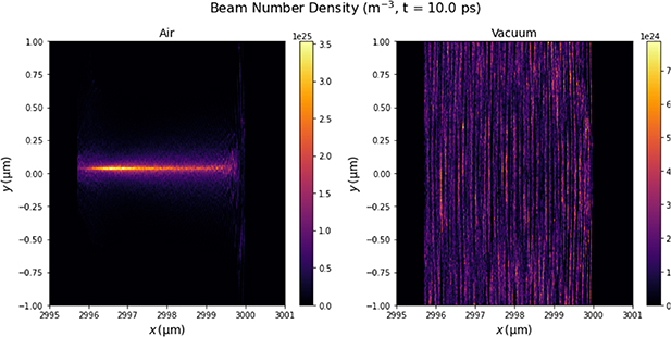
Figure 2. 2D beam density profiles after 10 ps propagation. Left figure is for an electron beam in a pre-ionised air plasma channel. The right figure the same beam but in vacuum.
Download figure:
Standard image High-resolution imageSince the background and beam electron densities at injection are typically different by a factor of ∼10 (over the Gaussian profile), charge neutralisation is most clearly seen in the magnitude of the transverse electric field Ey
. Charge neutralisation would correspond to Ey
= 0 in the beam. Figure 3 shows  averaged over the beam length at 5 ps. The flattened electric field in the beam corresponds to fe
∼ 0.8.
averaged over the beam length at 5 ps. The flattened electric field in the beam corresponds to fe
∼ 0.8.

Figure 3. Magnitude of radial electric field averaged over the beam length as a function of transverse coordinate y after 5 ps. Black dashed lines mark location 50% of maximum beam number density, grey dashed is 10%.
Download figure:
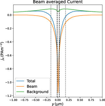
Standard image High-resolution imageFigure 4 shows the current density due to the beam and ionised air electrons. The central current channel has  A m−2 compared to the air current density of
  A m−2 suggesting a current neutralisation of fm
∼ 0.1. The estimates of fe
∼ 0.8 and fm
∼ 0.1 satisfy the condition for beam focusing and suggest a correction factor of ∼0.7 for the 3D estimates in section 5.
A m−2 suggesting a current neutralisation of fm
∼ 0.1. The estimates of fe
∼ 0.8 and fm
∼ 0.1 satisfy the condition for beam focusing and suggest a correction factor of ∼0.7 for the 3D estimates in section 5.
Figure 4. Current density averaged over the beam length as a function of transverse coordinate y after 5 ps for the beam electrons, background plasma and total current. Current density in units of PetaAmp/ . Dashed lines as in figure 3.
Download figure:
Standard image High-resolution image
Over the 10 ps duration of these simulations there is no evidence of instabilities which may disrupt the electron beam propagation. Current filamentation of the beam is likely only important when the beam width exceeds about twice the background plasma collissionless skin depth [21]. For the parameters tested here the skin depth is 0.7 µm so the σ = 0.36 µm beam is below the threshold for current filamentation. The electron beam velocity is close to c so its distribution is fully separated from that of the background plasma eliminating any possibility of kinetic bump-on-tail instabilities. The simulation time is ∼4000 plasma periods so any effects from two-stream instabilities must be weak if present at all. Nonetheless, longer kinetic simulations on the nanosecond time-scale would be needed to conclusively determine if instabilities could disrupt the electron beam propagation.
Finally, we note that while there is no noticeable deceleration of the beam over the 3 mm of propagation there is a stopping electric field in the beam-plasma system. The simulations above have an electric field along the beam axis of  which for γ = 400 gives an effective stopping of just
  . This can be improved by using higher energy beams as increasing the beam energy from 200 MeV to 10 GeV (the limit for current LWFA systems) increases the beam propagation out to 1 m. To get further than this the only option is to reduce the electron beam density since the stopping field produced by the beam-plasma interaction is proportional to the beam charge density. This has other potential benefits and is discussed further below.
7. Conclusions
It is possible to use a laser beam to generate a plasma column for an electron beam to travel through. This is achieved using a long laser beam (several nanoseconds) with the electrons injected into the tail of the laser beam. The electron beam will slowly overtake the laser beam, but will be travelling inside the beam all the while. The laser will ionise the plasma and make sure that it stays ionised in the region where the electrons are. The electron beam will then experience self-focusing due to its interaction with the plasma electrons. The analysis for 3D beams in section 5 applies to charge neutralised, free current beams ( ). 2D simulations have estimated the correction factor
  required for the 3D analysis to be ∼0.7 for the simulated beam-air parameters. This gives confidence in the analytic approach for the 3D Gaussian beams.
Plasma-based self-focusing of the electron beam is not strong enough to fully compensate beam divergence due to scattering off the plasma ions. The electrons will undergo a large number of small-angle collisions (see section 4) which will lead to a gradual divergence of the electron beam; this effect will always dominate over self-focusing in the long run. Self-focusing is not strong enough to cancel divergence completely, so a fully collimated electron beam (no divergence at all) is not possible. However, we found that self-focusing can curb the growth of the electron beam divergence over a limited distance, providing a beam with a constant divergence (beam radius will grow with the distance). For longer propagation distances, the beam will become so wide that self-focusing is no longer effective, and the beam radius will grow with the square of the propagation distance.
Problems with the proposed scheme, as analysed so far, are mainly that the IB heating of the background plasma will rapidly deplete the laser energy and the electron beam is slowed by the beam-plasma interaction. The first of these limits kJ class systems to generating ionised channels of at most ∼1 m. The second is more serious as for the parameters chosen for this initial study the stopping electric field within the electron beam, generated due to its focusing interaction with the background, would stop the electron beam after just 2 cm. However, the simulations completed here demonstrated that the stopping electric field strength scales with the electron beam charge. Thus using a lower density more energetic beam may be able to propagate further. For example a 10 GeV beam in the current setup would propagate for 1 m and if the beam and background plasma densities were both reduced to 10% of the values chosen above this would increase to 10 m. Running with a lower background plasma and beam charge density would also help to reduce IB losses. Provided the ratio of beam density to background plasma density remains roughly constant at ∼0.1 the focusing mechanism described above and estimates for fe and fm remain unchanged. However, this would require a pre-ionised channel with only 10% of Nitrogen atoms singly ionised. A significantly more computationally expensive parameter scan would be needed to optimise the parameters of background charge densities and electron beam energy.
Further analysis would need to consider the beam propagation including electron scattering, which would maintain a wider beam profile than simulated here, and the effect of the laser field on beam electron propagation. In addition, the practicality of pre-ionising a 10 m air channel with only 10% ionisation would need more careful modelling to include laser scattering effects and non-linear Kerr effect. The results in this paper do however show that if such an ionised air channel could be generated, then relativistic electron beam propagation is theoretically possible over ∼ 10 m distances for GeV electrons.
Data availability statement
The data generated and/or analysed during the current study are not publicly available for legal/ethical reasons but are available from the corresponding author on reasonable request.