

abstract
The results of an investigation of the wakefield around a stationary charged grain in an external magnetic field with non-zero transverse component with respect to the ion flow direction is presented. In contrast to the previously reported significant suppression of the wake oscillations due to the magnetic field applied along the flow, the wake potential exhibits long range recurrent oscillations in the presence a of transverse flow to the magnetic field. Extensive analysis for a wide range of parameters elucidate a strong dependence of the wake on the orientation of the magnetic field in the sonic and supersonic regimes by manifesting sensitivity to even a meager deviation of magnetic field from the longitudinal direction. The impact of the orientation and strength of magnetic field on the wake behavior is assessed. The deviation of the magnetic field induction vector from the longitudinal to ion flux direction leads to the wakefield with two positive peaks split in the transverse to ion flow direction in the downstream region; similar to that of the ultracold ions wake without magnetic field [(2020) New J. Phys. 22 033028].
Export citation and abstract BibTeX RIS
1. Introduction
Wakefield in a plasma manifests itself in a variety of physical phenomena e.g. dust acoustic waves, wake features, solitary structures etc, and has led to a paradigm shift [1, 2]. To understand these physical phenomena exhibited by complex plasma a number of methodologies has been pursued. To acquire the knowledge about controlled behavior of dusty plasma is one of the fundamental research problems investigated by complex plasma physicists. This controlled behavior of grain-plasma dynamics has often been achieved by applying external electric [3–7] and magnetic fields [8–13].
The study of dusty plasmas in vertical magnetic fields was first conducted by Fujiyama et al [14]. They investigated experimentally the transport of silicon particles by modulated magnetic field. Transport of silicon particle investigation is followed by the exploration of the inequalities of charge and number densities of electron, ion, and dust particle and discussion about the low-frequency dust-lower-hybrid modes in a dusty plasma [15]. Low frequency waves and magnetoacoustic modes in magnetized dusty plasmas were further investigated in detail [16, 17]. These studies discussed the drastic effect of magnetic field on levitating dust cloud shape control and rotation for strongly coupled dusty plasmas due to ion drag on fine particles and reported the dependence of rotation on plasma density variation. A decrease in the interaction force with increasing longitudinal magnetic field strength was also recently reported by Carstensen et al [18]. In another work, a different perspective for the effect of longitudinal magnetic field on complex plasmas was presented by Samsonov et al [19]. The work depicted the agglomeration and levitation of magnetic grains and proposed the possibility of magnetic field induced crystal formation, which in turn promoted interest in inter-disciplinary scientific interaction. Contemporary work for the same regime was carried out by Yaroshenko et al [20]. Their explanation for the mutual interaction was based on dipole theory and they delineated that field-aligned individual particle containing chains observed in experiments is due to the dipole short-range force [21, 22] which is induced by the wake formation behind a grain.
Observation of wake oscillations behind grains due to ion focusing is now one of the fascinating features displayed by complex plasmas and it has gained the reputation of being one of the most important phenomena observed in dusty plasma simulations. In recent works, influence of magnetic field aligned along flow on these wakes has also been investigated in great detail [10, 11, 18, 23, 24]. Furthermore, recent experiments have ignited the interest in magnetized dusty plasma studies by providing insight regarding the melting of crystal under the influence of a magnetic field [25]. As mentioned, dynamic wakefield has been observed to be a crucial attribute in determining the inter-grain interaction and has been anticipated to play a critical role in crystal formation. Despite the exciting progress, a theory dedicated to predicting the overall dynamics of the wake with reasonable precision and to answer questions such as, how the plasma dynamics gets altered by dynamic wake potential due to change in magnetic field strength and orientation, and whether there is a possibility of molecular-like interaction, is still lacking and needs to be addressed thoroughly.
Most of the previous works report the dynamic wakefield in an external magnetic field with non-zero longitudinal component only. The effect of transverse or inclined component of magnetic field on dynamic wake potential has not been explored so far using particle-in-cell simulation. The latter captures the effect of strong ion-charged grain coupling, which is an important feature of complex plasmas. Therefore, the prime objective of the present work is to develop fundamental insight on the effects of transverse component of an external magnetic field on the dynamic wakefield in complex plasmas and provide an overview of the characteristics distinct from those without magnetic field.
In the present work, magnetic field with non-zero transverse component to the ion flow direction is applied. The detailed numerical exploration for three different flow regimes (subsonic, sonic, and supersonic) for a wide range of magnetization is presented. Furthermore, a comparison of the results obtained with oblique magnetic field with the case of longitudinal magnetic field as well as the case without magnetic field is presented. The investigation has been performed with Maxwellian ion distribution which should be changed to non-Maxwellian for pressures greater than 10 Pa and other appropriate situations.
The outline of the paper is as follows: An introduction of the numerical simulation scheme and brief description of the method is given in section 2. In section 3, the results regarding the influence of the magnetic field with non-zero transverse component on the wakefield is discussed. In section 3.1, purely transverse magnetic field case (i.e. with zero longitudinal component) is considered. Then, in section 3.2, the intermediate regime with non-zero transverse and longitudinal components of magnetic field induction is explored. Finally, a summary and conclusion is presented in section 4.
2. Simulation details and plasma parameters
The case relevant to gas discharge plasmas is considered wherein the dust particle is located in a flux of ions with background electrons at least hundred times hotter than ions [26, 27].
2.1. Particle-in-cell simulation
The wake features around a grain were explored with coptic particle-in-cell simulations [28]. The simulated system consists of a stationary charged grain in the presence of streaming ions under the influence of an external magnetic field. Besides providing comparatively accurate solutions for even non-linear regime, the importance of the code lies in the fact that it can be customized to resolve the particle in the near neighborhood of grain by orders of magnitude than elsewhere by imposing a non-uniform grid in the vicinity of the grain. The simulation set-up is similar to the one considered in the recent works [6, 11, 23, 29] except that we have a magnetic field component perpendicular as well as parallel (few cases) to the flow direction. Further, numerical detail and fundamentals can be learned from the paper with descriptions about coptic [28, 30].
coptic facilitates the incorporation of point-charge grains as well as finite-sized objects. The grain considered in the present work is point-charge and is solved using particle-particle particle-mesh (P3 M) technique. The ion dynamics in six-dimensional phase space in the presence of the self-consistent electric field −∇φ of plasma, an optional external force D [30] (this extra force  is zero in our simulations for the shifted Maxwellian distribution) and an external magnetic field
  is delineated by the equation
here q and mi denote the ion charge and ion mass respectively.
To introduce a constant flux of ions, we used shifted Maxwellian distribution with a given value of the ions drift velocity (Much number). In order to solve the Poisson equation, a second-order accurate finite-difference-scheme equivalent to Shortley-Weller approximation has been adopted. The solution of this Poisson equation,

endows us with the resultant potential where electron and ion number densities are represented by ne and ni respectively,. The interpolation of the electric field and the solution of the Poisson equation is incorporated with higher precision and convergence as it uses compact difference stencil which is specialized in dealing with arbitrary oblique boundaries for Cartesian mesh as well. On the outer mesh-edge, the potential gradient along  is set to zero.
At considered ordinary laboratory dusty plasma parameters, the charge of the dust particle is about  (with e0 being the electron charge) [1]. Therefore, the dust particle is considered to be strongly electron repellent, i.e. the ion-collecting probe approximation is applied. In this regime, the integration of the steady-state parallel momentum equation shows that the electrons are Boltzmann distributed [31–34]:

The combination of equation (1) with B ≠ 0 for ions and of equation (3) for electrons is the basis of the hybrid Boltzmann-particle-in-cell (pic) codes with a background magnetic field [32, 33, 35]. Patacchini et al [35] showed the validity of such hybrid approach for the entire range of ion magnetization for the strongly electron repellent dust particle (probe) by making an explicit comparison of the results computed using full pic (electron and ion particle) code calculations with the hybrid approach. The hybrid approach considered here has also been used previously, e.g. to study wave dispersion relations of magnetized dusty plasmas [34, 36].
In the code, collisions are included according to the constant velocity-independent collision frequency Poisson statistical distribution which is similar to the BGK-type collisions. Predominant collision in the system is the ion-neutral charge-exchange collision. This charge-exchange collision is implemented in the code by the mutual exchange of the ion velocity with the neutral velocity randomly drawn from neutral velocity distribution.
We also performed few simulations with grids of even higher resolution and non-uniform mesh spacing to resolve the dynamics in the vicinity of the grain [28]. Simulation is progressed in time for 1000-2000 time steps (with units discussed below) by which it usually reaches steady-state.
2.2. Dimensionless quantities and plasma parameters
The most important dimensionless parameters are as follows:
- (a)The orientation of the magnetic field is characterized by the angle α between magnetic field induction vector and streaming (an external electric field) direction (which is along z axis) as illustrated in figure 1. For 0 ≤ α ≤ π/2, the absolute transverse magnetic field and absolute longitudinal magnetic field cases correspond to α = π/2 and α = 0, respectively.
- (b)The strength of the magnetic field is conveniently and conventionally characterized by the parameter
 defined as the ratio of cyclotron frequency of an ion to the plasma frequency of ions. Dimensionless parameters α and β are sufficient to completely describe the magnetic field.
 - (c)Mach number M describing ionic streaming speed has been defined as, where is the ion sound speed and vd is ionic streaming velocity. Thermal Mach number Mth shares the relation with Mach number M according to the relation .


Figure 1. Schematic depicting the system of grain in streaming ions in the presence of electric and magnetic fields.
Download figure:
Standard image High-resolution imageBesides, we follow the standard normalization, as described in [28], i.e. the space coordinate is normalized as  , velocity as
  , and potential as
  , where
  is the normalizing scale length and cs is unity in normalized units. Time units as
  is used to normalize collision frequency ν, where ωpi is the ion plasma frequency. The normalized grain charge, Qd, is represented as
  , where e0 is the unit electron charge. We considered a cell grid of 64 × 64 × 128 with more than 60 million ions and grid side length of 15 × 15 × 20 Debye lengths for simulation purposes.
A summary of plasma parameters are presented in table 1. For typical dusty plasma parameters (e.g. an electron Debye length of λde = 845 µm and an electron temperature of 2.585 eV), the normalized grain charge  redacted in units of electron charge is approximately
  and β ≤ 1.0 is the magnetization parameter corresponding to
  . These parameters are chosen in accordance with those observed in dusty plasma experiments [25, 37–39].
Table 1. List of plasma and simulation parameters.
| Physical property | Parameter range |
|---|---|
| Magnetization β | 0.0-1.0 |
Temperature ratio  |
100 |
| Mach Number M | 0.5 - 1.5 |
| Collision frequency ν/ωpi | 0.002 |
Normalized grain charge  |
0.01 |
3. Results
3 Study of grain under streaming ions in the presence of cross-flow magnetic field serves the twofold objective of (a) investigation of the influence of magnetic field applied perpendicular to the flow and (b) a study of the intermediate case with non-zero transverse and longitudinal components of magnetic field. For all simulation runs, a dust particle is located at the origin  (in Cartesian co-ordinate) and is post-processed to provide the result in cylindrical co-ordinate (with grain located at z = 0 and r = 0).
3.1. Impact of a transverse magnetic field on the dust wake
Formation of wake behind grain due to ion focusing followed by defocusing for the unmagnetized case has been well investigated. A comparison of such a wake without magnetic field with that in the presence of magnetic field (two extreme cases - one magnetic field along flow and the other perpendicular to flow) is first presented to elucidate the impact of orientatation and strength of magnetic field on wake structure formation. In figure 2, the contour plots of the potential for three distinct cases: (a) without magnetic field (β = 0), (b) magnetic field applied along flow ( ), and (c) magnetic field in a direction transverse to the flow (
 ) are illustrated. Figure 2 demonstrated that the considered three cases have different wake structures. In the well studied magnetic field free case, figure 2(a), we see a V-shape wakefield with interchanging maxima and minima along flow direction. The wakefield with an external magnetic field applied along streaming velocity—another in detail investigated situation [10, 11]—shows no such oscillatory pattern with 'candle flame' shape (see figure 2(b)).

Figure 2. Wake potential contours eφ/Te, averaged over the azimuthal angle, with the ion flow velocity M = 1.0 for: (a) without magnetic field (β = 0.0), (b) with magnetic field applied along streaming direction (β = 1.0 and α = 0), and (c) with magnetic field in transverse direction with respect to the flow (β = 1.0 and α = π/2).
Download figure:
Standard image High-resolution imageThe rotation of the magnetic field orientation from longitudinal to transverse direction restores oscillatory pattern of the wake field as illustrated in subplot (c) of figure 2. The noticeable differences of the latter case, figure 2 (c) from the magnetic field free case, figure 2 (a) are a stronger localization of the ion focusing and depletion regions around maxima and minima accompanied by a weaker manifestation of the V-shape, and a weakened damping of these oscillations. We also notice the sustained long range oscillatory structures with reduced effective wake wavelength in the case of grain in transverse to flow magnetic field (cf subplot (c)) and will be discussed later. In dimensional units, for typical dusty plasma parameters, e.g. Te = 2.585, β = 1.0, and M = 1, the first wake peak would correspond to a potential of 60.62 mV for magnetic field transverse to flow and 25.98 mV for magnetic field along flow [11].
Next, in figure 3, we consider the wakefield for the transverse to flow magnetic field with different magnetization parameters at subsonic, sonic, and supersonic speeds. The three rows of the figure denote the cases with three different Mach numbers M = 0.5, M = 1, and M = 1.5 (from top to bottom), while the four columns show the cases with increasing strengths of magnetic fields β = 0.05, β = 0.1, β = 0.2, and β = 0.4 (from left to right). For M = 0.5 (top row), magnetic field decreases the oscillations amplitude and the following recurrent maxima and minima. The amplitude of wake oscillation is so small that no explicit trend is observed. Further increasing the magnetic field strength up to β = 0.4, one can observe an extended positive potential region which completely wipes out the secondary peaks at subsonic flows. Increasing the flow speed to M = 1 (middle row) and M = 1.5 (bottom row), pronounced wake oscillations behind the grain is observed. With increase in β, the effect of magnetic field manifests in the increase of the number of oscillations and decrease in the distance between subsequent potential maxima and minima. Additionally, the aforementioned stronger localization of the wake pattern around maxima and minima is distinctly visible. This can be understood by the characteristic trajectory opted by ions in weak and moderate magnetic field strengths. In the presence of magnetic field, the flow acquires anisotropy which leads to different plasma dynamics along and perpendicular to flow. At very weak magnetization ions follow the path as they do in the magnetic field free case. However, at moderately strong magnetic field strength, the ions get magnetized and the motion of ions gets more restricted around magnetic field induction lines. This leads to a stronger localization of the charges behind grain and a shortened characteristic wake oscillation wavelength.

Figure 3. Wake potential contours eφ/Te for various strengths of magnetic field. From left to right, he first column corresponds to β = 0.05, the second column is for β = 0.1, the third column is for β = 0.2, and the right column is for β = 0.4. The ion flow velocity M = 0.5 (top row), M = 1.0 (middle row), and M = 1.5 (bottom row).
Download figure:
Standard image High-resolution imageTo further investigate the influence of the transverse magnetic field, the wake potential along the streaming axis at M = 0.5, 1, and 1.5 along with almost unmagnetized or very feeble magnetic field case (β = 0.05) is shown in figure 4. It was found that β = 0.05 case provides similar wake potential characteristics as the magnetic field free case already reported in previous works [6, 10, 11, 40]. At subsonic and sonic speeds (top and middle panel respectively), the transverse magnetic field with β = 0.1 leads to the substantial deviation of the potential from the case β = 0.05. However, in the supersonic regime (bottom panel), data for β = 0.1 case weakly differs from β = 0.05 case. With further increase in the magnetic field strength to β = 0.2 and β = 0.4, a strong impact of the transverse magnetic field in all three subsonic, sonic and supersonic regimes is observed. In this case, the transverse magnetic field decreases the oscillations amplitude as well as the distance between maxima and minima of the wakefield.

Figure 4. Wake potential along the streaming axis for transverse to flow magnetic field ( α = π/2) with β = 0.05 (blue solid line with circle), β = 0.1 (red long dashed line with triangles), β = 0.2 (olive dashed lines with squares), and β = 0.4 (green dotted line with hexagon) for M = 0.5 (top panel), M = 1.0 (middle panel), and M = 1.5 (bottom panel).
Download figure:
Standard image High-resolution imageIn figure 5, the potential profile along transverse direction with z = 0 is shown. This figure shows that the transverse magnetic field with β ≤ 0.4 does not change the potential profile in perpendicular direction to z axis at z = 0. This is an important information, as in experiments, the dust particles are often located on a single plane perpendicular to the flow direction. Moreover, this behavior is in contrast with the longitudinal magnetic field case reported in previous works [10, 11, 23] where it was reported that the longitudinal magnetic field substantially affects the potential profile perpendicular to z axis (streaming direction) at the grain location (z = 0).

Figure 5. Wake potential in transverse to flow direction (with z = 0, α = π/2 and M = 1.0) for magnetic field with β = 0.05 (blue solid line with circle), β = 0.1 (red long dashed line with triangles), β = 0.2 (olive dashed lines with squares), and β = 0.4 (green dotted line with hexagon) for M = 1.0.
Download figure:
Standard image High-resolution imageFor completeness, the wake peak height dependence on β is given in figure 6 for transverse to flow magnetic field. In agreement with the above presented wake potential data, the wake peaks are substantially smaller at M = 0.5 compared to sonic and supersonic cases. An increase in the flow speed leads to an increase in the wake peak amplitude (M = 1) followed by a significant decrease (M = 1.5) at even higher streaming speed. This behavior is due to the competition between increase in the number of influx ions and higher escape ability of ions with increase in streaming speed. Magnetic field applied perpendicular to the flow does not alter this non-monotonic trend with respect to change in the flow speed. The data for stronger magnetic field exhibits the smaller wake peak amplitude in accordance with those obtained for magnetic field applied along flow [11]. However, the relative damping of the oscillations is weaker in downstream direction compared to the longitudinal magnetic field case.

Figure 6. Variation of the maximum of the peak amplitudes of the wake potential as a function of β with α = π/2.
Download figure:
Standard image High-resolution imageIn figure 7, the variation of the first maxima for the wake potential amplitudes as a function of Mach number, M, at α = π/2 is elucidated. In figure 7 the comparison of the magnetized wake potential peak (with β = 1) to the wake potential peak without an external magnetic field is shown. In the latter case the value of the potential is significantly larger than in the magnetized case. For illustrative comparison of these two cases, the value of the magnetized wake potential peak is multiplied by the factor 10. From figure 7 we see that the wake potential maxima exhibits a non-monotonic curve with change in ion flow speed. In the magnetized case, the characteristic trend is qualitatively similar to the one observed without magnetic field, however, the quantitative values are significantly different. In the absence of the magnetic field, the wake peak first increases with increase in the flow strength up to Mach number M ≃ 0.5 and then decreases with further increase in flow strength. Similar behavior exhibits the wake peak with magnetic field (β = 1), but with maxima around M = 1.0 and with much slower decline after maxima with further increase in the ion flow velocity. The increase of the wake peak potential value with increasing the ion streaming velocity at small M is due to enhancement in ion focusing downstream grain and followed decline in the peak strength at large M is because ions can effectively escape the attraction by negatively charged grain.

Figure 7. Variation of the first maximum of the weakfield potential as a function of Mach number, M, with α = π/2. The comparison of the result for the magnetized case (β = 1) with the case without magnetic field (β = 0) is shown. For illustrative proposes, the potential value at β = 1 is multiplied by the factor ten.
Download figure:
Standard image High-resolution imageThe presence of recurring oscillations downstream grain with similar shaped potential maxima and minima is illustrated in figure 8 where β = 0.125, α = π/2, and M = 1. Here, the wake potential has oscillatory pattern extending up to  in downstream region. It reveals that wake of purely oscillatory character in downstream region with a length of order ten λde can be achieved with modification in the strength and orientation of magnetic field.

Figure 8. figure showing three-dimensional view of recurrent oscillations (with minima and maxima of the similar size) downstream grain in the presence of transverse to flow magnetic field with parameters β = 0.125, α = π/2, and M = 1.
Download figure:
Standard image High-resolution imageThe ion density contour profile also supports the discussed wakefield variation in the presence of transverse magnetic field and is illustrated in figure 9 for flow speed M = 1.5 at β = 0.05, 0.1, 0.2, and 0.4. It is known from the work by Sundar et al [11] that the presence of longitudinal magnetic field induces 'candle flame' like ion density distribution in downstream region. However, there is no visible 'candle flame' like protruding structure in the density contour in the case of the magnetic field applied perpendicular to the flow direction. Additionally, transverse magnetic field makes the density fluctuation propagate farther from the grain thereby extending the range of wake oscillations. This supports our observation of enhancement in the number of wake potential oscillations behind grain at sonic and supersonic speeds.

Figure 9. Spatial profiles of the ion density (normalized to the distant unperturbed ion density) for for M = 1.5, α = π/2, and (a) β = 0.05, (b) β = 0.1, (c) β = 0.2, and (d) β = 0.4.
Download figure:
Standard image High-resolution image3.2. Effect of deviation of magnetic field orientation from longitudinal direction
It is shown above that the wake behavior for the case of longitudinal magnetic field is completely different from that of magnetic field applied perpendicular to the flow. Therefore, it is interesting to inquire the intermediate case, i.e. when both longitudinal and transverse components of the magnetic field are non-zero. The consideration of the intermediate configuration provides the implicit detail about the influence of deviation of magnetic field orientation from the longitudinal direction on the wake features.
Figure 10 depicts the influence of magnetic field orientation on the wake potential at the subsonic (top row), sonic (middle row), and supersonic (bottom row) speeds. Here, to explicitly reveal the part played by the orientation of the magnetic field on the wake pattern, the strength of the overall magnetic field is kept intact (with β = 1.0) and variation in  and
and  components is considered. In figure 10, from left to right, the strength of the magnetic field component
  (along the ion flux) reduces and consequently, the strength of the transverse component
  increases. Accordingly, the angle between the ion flux direction and magnetic field induction direction, α, changes from 0° [the left column] to 36° (0.64 rad)[the right column] with intermediate value corresponding to 10° (0.2 rad) [the middle column]. It can be observed that a change in the orientation of magnetic field modifies the wake behavior substantially. For the sonic and supersonic cases, a small deviation of the magnetic field direction from the purely longitudinal case has a very strong effect on the plasma dynamics around grain which eventually changes the wakefield pattern (compare the left pair of columns). This is especially strongly manifested in the supersonic regime (M = 1.5, see the bottom row) where even a 10° deviation of the magnetic field induction from the longitudinal direction creates absolutely different pattern of the wake field in comparison with the purely longitudinal case (i.e.
  ). In contrast to the sonic and supersonic cases, in the subsonic regime the wake field modifies smoothly with the rotation of the magnetic field induction direction from transverse to longitudinal configuration.

Figure 10. Wake potential contours eφ/Te with the ion flow velocity M = 1.0 and magnetization parameter β = 1.0 for various orientation angle of magnetic field α, where α is the angle between magnetic field direction and ionic streaming direction [i.e. z axis]. From left to right column we have α = 0 [i.e.  with
with  ], α = 0.2, and α = 0.64.
Download figure:
Standard image High-resolution imageIn figure 11, the variation of the position and amplitude of the first wakefield maximum with orientation of magnetic field is illustrated for M = 1. From top subplot of figure 11, one can see that at  the position along z axis of the first potential peak remains almost unchanged with increase in α. Then at α > π/12, z coordinate significantly drops meaning that the first positive peak appears closer to the grain. At
  , further deviation of the magnetic field induction direction from the longitudinal to flow orientation does not change the position of the peak. The amplitude of the potential peak is shown in bottom subplot of figure 11. The value of the potential peak first slightly decreases with increase in α at
  . At
. At  , further deviation from the longitudinal direction results in a drastic increase in the potential peak value. For the range
  , the potential peak amplitude remains approximately unaffected with variation in α. A non-monotonic behavior of the potential peak value and its location with change in magnetic field direction reaffirms that the deviation of the magnetic field orientation from the parallel to ion flow direction affects the wake peak potential, peak position and structure substantially.
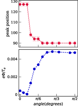
Figure 11. figure showing the variation of first wake peak potential value (bottom subplot) and its location (top subplot) versus angular orientation of magnetic field at β = 1 and M = 1.
Download figure:
Standard image High-resolution imageInterestingly, when both longitudinal and transverse components of the magnetic field are non-zero, the formation of two positive peaks split in transverse direction behind grain can be seen in figure 12 at β = 1 and α = 0.21. Two peak formation downstream grain in the presence of oblique to flow magnetic field is not a generic feature rather unique as it depends on the interplay of the perpendicular  as well as parallel
  magnetic field effects. The potential distribution in transverse direction at the location of two peaks is illustrated explicitly in figure 13 where comparison with the case z = 0 is also shown. In figures 12 and 13, there are no positive peaks at the location of the grain (z = 0), but the two peaks are clearly visible in the vicinity of the grain in the downstream region. This feature is qualitatively similar to the two positive peaks observed in ultracold dusty plasmas [41]. This observation is interesting in the sense that certain characteristics observed by lowering the temperature can be achieved by changing the strength and orientation of magnetic field [41, 42]. Nevertheless, there are differences in the two cases in the mechanism of wake formation and peak splitting. Here, the two positive potential peaks are separated by negative potential region and these are followed by further oscillations downstream whereas in the ultracold dusty plasmas there is a molecular-like structure with only two positive peaks behind grain.

Figure 12. figure emphasizing the formation of two peaks in the potential downstream grain for an inclined magnetic field at β = 1, M = 1, and α = 0.21.
Download figure:
Standard image High-resolution image
Figure 13. figure showing the potential transverse to flow at the center of the grain (z = 0) and at the maxima of the twin peak location ( ) at β = 1 and α = 0.21.
Download figure:
Standard image High-resolution image
4. Discussion and conclusion
The present work provides a comprehensive picture of the influence of the transverse magnetic field on the grain wakefield and reveals the important role played by the orientation of the magnetic field. The investigation has been performed with Maxwellian ion distribution and the effect of non-Maxwellian ions in transverse magnetic field is a topic for forthcoming studies. Weak to moderately strong magnetization of ions is considered with β ≤ 1.0 in subsonic, sonic, and supersonic regimes with Mach number M ≤ 1.5.
Several new features of wakefield due to transverse magnetic field is explored and presented. First of all, under the influence of the transverse magnetic field component, the number of wake oscillations increase in comparison to the magnetic field free case. This is also in stark contrast to the case of magnetic field along flow [10, 11]. Secondly, the damping of the amplitude of wakefield oscillations is not as strong as that observed for parallel to the flow magnetic field. Another remarkable result we demonstrated herein is that relatively small deviation ( ∼ 10° ) of the orientation of magnetic field induction from the ion flow direction leads to a significant wakefield modification in downstream region. Change in orientation of magnetic field also signifies the possibility of formation of molecular-like interaction regions as the twin peak formation takes place(e.g. at β = 1, α = 0.21, and M = 1) in the downstream grain region.
To understand weaker damping of the wake with deviation of the magnetic field direction from parallel to ion flux, we need to recall kinetic theory result that the damping of the induced waves (wake) is due to particles satisfying the condition [43]:

where  is the component of the velocity (wave vector) along magnetic field induction and n = 0,± 1,± 2, .... On the right hand side of equation (4), the first term corresponds to the damping due to Cherenkov type ion density excitation and the second term corresponds to the damping due to the cyclotron mode of the ion density excitation. The connection of the density excitation to the dissipation is also evident from the fluctuation-dissipation theorem [44].
One can rewrite equation (4) as,
From condition (5) it is clear that the damping is effective when the ion flux velocity is along  and the damping gets minimized when the ion flux velocity is perpendicular to
  . Note that equation (4) is valid for
  .
.
Foregoing kinetic explanation of damping behavior provides a qualitative understanding of recurrent oscillatory wake pattern downstream grain for transverse to flow magnetic field case.
Magnetic field along flow has been known to provide shape control of dust cloud and influences the wake amplitude as well as overall structure of the grain plasma dynamics (see e.g. [45–47]). Wake formation has also been attributed the prime reason for vertical alignment of paired grains. Essentially,  field could be of utmost importance for future research for dust shape control and controlled grain-grain/grain-plasma interactions. Therefore, the presented results are crucial for the description of the complex plasma experiments in weak to moderate external magnetic field [8]. The tool obtained with the present investigation is anticipated to be used to potentially maneuver the grain-grain interaction to achieve controlled grain dynamics.
Furthermore, the presented results can also be useful in providing a better understanding of other phenomena involving the motion of particles in cross fields, e.g. the dynamics of scramjet mixing and charge focusing with electric or magnetic fields. On a final note, we mention that the work studied herein should be of interest for open challenges in astrophysics, e.g. the dynamics of trapped particles in Van Allen Belts [48], the Saturn ring spokes formation [49] as well as other astrophysical phenomena wherein the motion of dust particles encounter magnetic field and streaming plasmas.
Acknowledgments
S Sundar would like to acknowledge the support and hospitality of IIT Madras India. This work was supported by the DRDO project via project no. ASE1718144DRDOASAM. Zh Moldabekov thanks the funding from the Ministry of Education and Science of the Republic of Kazakhstan via the grant AP08052503. Our numerical simulations were performed at the HPC cluster of IIT Madras.