

Abstract
Brain stereotactic radiosurgery (SRS) treatments require multiple quality assurance (QA) procedures to ensure accurate and precise treatment delivery. As single-isocenter multitarget SRS treatments become more popular, the quantification of off-axis accuracy of the linear accelerator is crucial. In this study, a novel brain SRS integrated phantom was developed and validated to enable SRS QA with a single phantom to facilitate implementation of a frameless single-isocenter, multitarget SRS program. This phantom combines the independent verification of each positioning system, the Winston-Lutz, off-axis accuracy evaluation (i.e. off-axis Winston-Lutz), and the dosimetric accuracy utilizing both point dose measurements as well as film measurement, without moving the phantom. A novel 3D printed phantom, coined OneIso, was designed with a movable insert which can switch between the Winston-Lutz test target and dose measurement without moving the phantom itself. For dose verification, ten brain SRS clinical treatment plans with 10 MV flattening-filter-free beams were delivered on a Varian TrueBeam with a high-definition multileaf collimator (HD-MLC). Radiochromic film and pinpoint ion chamber comparison measurements were made between the OneIso and solid water (SW) phantom setups. For the off-axis Winston-Lutz measurements, a row of off-axis ball bearings (BBs) was integrated into the OneIso. To quantify the spatial accuracy versus distance from the isocenter, two-dimensional displacements were calculated between the planned and delivered BB locations relative to their respective MLC defined field border. OneIso and the SW phantoms agree within 1%, for both film and point dose measurements. OneIso identified a reduction in spatial accuracy further away from the isocenter. Differences increased as distance from the isocenter increased, exceeding recommended SRS accuracy tolerances at 7 cm away from the isocenter. OneIso provides a streamlined, single-setup workflow for single-isocenter multitarget frameless linac-based SRS QA. Additionally, with the ability to quantify off-axis spatial discrepancies, we can determine limitations on the maximum distance between targets to ensure a single-isocenter multitarget SRS program meets recommended guidelines.
Export citation and abstract BibTeX RIS
1. Introduction
With the recent advances in radiation oncology, such as those presented in the SABR-COMET clinical trial (Palma et al 2019), there will be an imminent increase in the number of multitarget stereotactic radiosurgery (SRS) treatments for patients that would have otherwise been treated with palliative standard of care therapies alone. The current workflow for the treatment of multiple brain metastases revolves around a multi-isocenter setup, aligning each isocenter at the individual metastatic lesion using systems such as CyberKnife (Accuray, Sunnyvale, CA). Unfortunately, the treatment duration for a multi-isocenter technique is roughly proportional to the number of lesions treated, resulting in extended treatment time (>1 h) for multiple lesions (on average 30 min per metastatic lesion) (Mcguinness et al 2015). Accordingly, frameless single-isocentric approaches are becoming more prevalent with the aim to reduce the overall treatment time without compromising on coverage or dose delivery (Kamath et al 2005, Pan et al 2012). Frameless linear accelerator (linac) volumetric-modulated arc therapy (VMAT) based single-isocenter, multitarget (SIMT) cranial SRS programs have the ability to improve efficiency by reducing overall treatment times and increase patient comfort (Clark et al 2010). Open mask-based frameless SRS treatments have been shown to have outcomes equivalent to frame based systems (Kamath et al 2005, Breneman et al 2009, Minniti et al 2011), and provide fast treatments when combined with flattening-filter-free (FFF) x-ray beams on modern medical linacs. Optical surface monitoring systems have also been shown to provide sub-millimeter verification of patient positioning, which is especially useful in non-coplanar situations where on-board imager (OBI) systems are of limited use (Mancosu et al 2016, Oliver et al 2017).
Currently, brain SRS treatments require several quality assurance (QA) procedures to ensure accurate and precise treatment delivery—specifically two QA objectives of positioning and dosimetric accuracy which require multiple phantom setups. Modern radiotherapy linacs typically consist of many independent positioning systems each with their associated QA tests (kV, MV, cone-beam computed tomography (CBCT) imaging, optical surface imaging, etc) to assist in delivering high levels of radiation therapeutically. These many independent systems require alignment using multiple phantom setups which limits the accuracy, introduces potential for error, and increases time burden for QA. For frameless treatments, this alignment is critical as sub-millimeter accuracy is required. While many different SRS QA phantoms already exist, the majority focus on radiographic systems (MV), less encompass the OBI system (kV) and optical surface imaging systems. Typically, one or more film planes are used to provide high resolution verification of the dose distribution. Example phantoms of this type include M037 (CIRS), STEEV (CIRS), Lucy (Standard Imaging), SRS QA (Varian), MAX-HD (IMT), StereoPHAN (Sun Nuclear) (Ramani et al 1995, Sarkar et al 2016, Dimitriadis et al 2017, Yu et al 2018, Poder et al 2018, Ahmed et al 2019). Recent studies have investigated the combination of SRS MapCHECK device within the StereoPHAN phantom (Sun Nuclear) which demonstrated the ability to perform commissioning and QA, including SIMT plans, albeit the device is limited for some cases due to the inability to sample certain beams at their planned angles (Ahmed et al 2019). Additionally, novel methods to visualize multifocal radiosurgery plans implementing an N-isopropylacrylamide polymer gel dosimeter as well as CBCT—incorporating both the radiographic (MV) and OBI (kV) systems on a medical linac (Adamson et al 2019, Pant et al 2020). Furthermore, in regard to treating multiple targets with a single-isocentric approach, the off-axis accuracy of the linac is crucial. The common Winston-Lutz test is limited to only evaluating spatial accuracy at the isocenter. Commissioning multitarget frameless single-isocenter SRS requires a rigorous QA program—specifically designed to quantify the spatial accuracy of a linac as a function of distance from the isocenter (Stanhope et al 2016). To date, there is no standardized QA phantom to perform such a task to perform the Winston-Lutz test and dose measurement within in a single phantom, albeit a commercially available product has been recently released (StereoPHAN MultiMet-WL Cube, Sun Nuclear). Without such a QA program, the confidence in treating multiple lesions using one isocenter is unlikely to be achieved in clinical practice, because of the uncertainty in the behavior of an individual linac.
In this study, we developed, designed and validated a novel integrated phantom, coined OneIso, to assist in facilitating the implementation of a frameless SIMT cranial SRS program to improve work efficiency and patient experience. OneIso seeks to solve the issues of co-alignment of multiple independent positioning systems (to simplify the QA process and reduce errors), and integrate dosimetric verification (through both a point measurement and film) as well as to fill the current gap with prospectively determining the uncertainty in spatial accuracy as a function of distance from isocenter. This uncertainty at a given distance from isocenter, can then be incorporated into planning target volume margins. The QA phantom will facilitate and simplify the translation of this frameless VMAT radiosurgery technique, which is critically needed for the commissioning of linacs to perform frameless SIMT SRS treatments. Moreover, the simplicity of the OneIso will enable clinical translation of this highly sought-after workflow solution to not only larger institutions, but also to community clinics.
2. Materials and methods
2.1. Phantom design and construction
The OneIso phantom was designed in Fusion 360 (Autodesk, San Rafael, CA) and printed using an Ultimaker S5 three-dimensional (3D) printer (Ultimaker, Cambridge, MA), shown in figure 1. The design of the phantom builds on our previously designed and validated integrated phantom which allows independent verification of each positioning system and coincidence of each system (kV, MV, CBCT, optical surface imaging, Winston–Lutz test, light/radiation field coincidence and lasers) using a single setup (Yu et al 2018). We have shown previously with this 3D printed phantom that optical surface monitoring QA can be performed, where we observed submillimeter accuracy (Yu et al 2018).
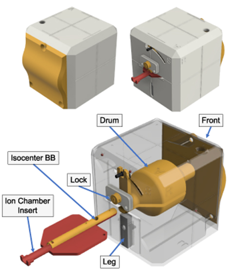
Figure 1. An integrated SRS QA 3D printed prototype phantom, named OneIso. The phantom is constructed of four major component groups and a total of 12 3D printed parts. Notch-lock mechanisms were designed to lock the central ion chamber insert in-place. The front plate is curved to create a feature for the optical surface imaging system. Inside there is a solid central drum. This drum contains two steel BBs: one in the center for the Winston-Lutz test as well as one to aid in determining the off-axis Winston-Lutz. Three steel BBs are within the printed shell of the phantom. Inside the drum, there are two independent inserts which contain the isocenter BB as well as either an ion chamber (shown above) or film insert.
Download figure:
Standard image High-resolution imageThe printing materials used were polylactic acid (PLA) and nylon plastics. Nylon was chosen for critical mechanical components due to its higher fracture toughness, and lower friction coefficient than PLA, whereas its ease of printing meant that PLA was favored for all other components. The phantom also includes one 6 mm diameter central tungsten ball bearing (BB) for Winston-Lutz tests and a row of four off-axis 3 mm diameter steel BBs used to determine the off-axis accuracy of the linac (off-axis Winston-Lutz test), shown in figure 2. The design was optimized for 3D printing by minimizing overhangs in any single piece.

Figure 2. Design of the OneIso phantom to quantify the spatial accuracy of a linac based SIMT cranial radiosurgery system. The phantom contains a row of off-axis BBs (A) designed to have no overlap with any BBs in the anterior-posterior and lateral directions (B). The red and blue arrows represent the central BB for the Winston-Lutz test as well as the BBs for the off-axis Winston-Lutz test, respectively.
Download figure:
Standard image High-resolution imageThe phantom (figure 1) is constructed of four major component groups, and a total of 12 3D printed parts, five BBs, and four nylon bolts. From the outside in, the major parts are the 5-sided outer shell and the front plate which is curved to create a feature for the optical surface imaging system. Inside there is a solid central drum, printed in PLA plastic at a density of 1.15–1.2 g cc−1. This drum contains one holder place for one steel BB. This central drum is connected to a rocking arm that allows for ±45∘ angle adjustments. The 45∘ rocking arm allows for an alternative dose plane for film measurements. Inside the drum, there are two independent inserts which contain the isocenter BB and either an ion chamber (figure 3(A)) or a film (figure 3(B)) insert. The inserts are printed in two parts that mate together (figure 1); and slides between two positions: fully inserted for the ion chamber at isocenter, and a second position, that can be locked in-place, where the BB is at isocenter (figures 3(C) and (D)). The two-part construction ensures that the central BB, and ion chamber or film placement can be easily changed or inspected.
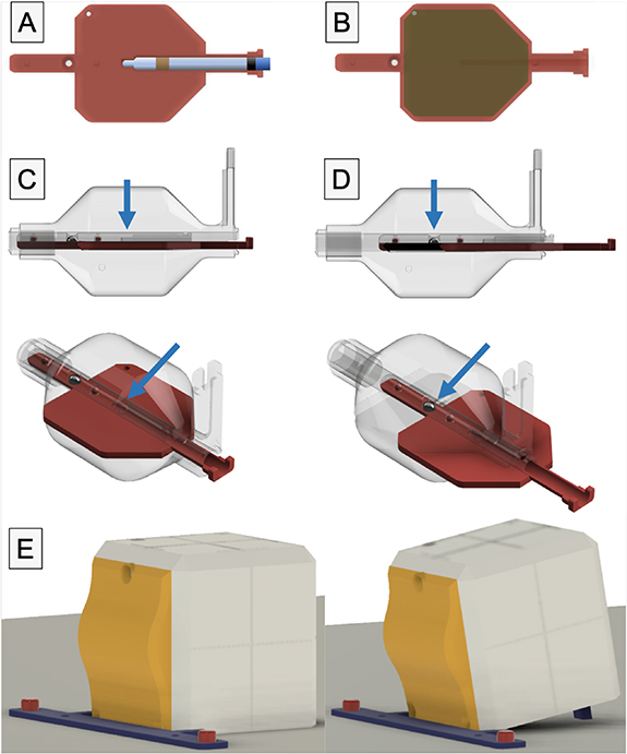
Figure 3. Inside the drum, there are two independent inserts which contain the isocenter BB as well as either an ion chamber (A) or film (B) insert. The insert is printed in two parts that mate together, and slides between two positions: (C) fully inserted for either the film or the ion chamber at isocenter, and (D) a second position, that can be locked in-place, where the BB is at isocenter. (E) Shows the 10∘ tilt of the phantom against the exact bar mount for QA of optical surface monitoring systems.
Download figure:
Standard image High-resolution imageThe main outer shell is 120 × 120 × 120 mm3 with 2 mm wall thickness and chamfered corners to increase durability. Notch-lock mechanisms lock the central ion chamber insert in-place. An extendable leg allows the user to tilt the phantom 10∘, enabling verification of the angles reported by the optical surface imaging system (figure 3(E)). To ensure the phantom remains stationary, a couch index bar mount was designed, and 3D printed. It slides over the two 9'' spaced ½'' diameter pins on the Varian Exact bar (Varian Medical Systems, Palo Alto, CA) and is compatible with several indexing bars designs, such as the iBEAM indexing bar (Elekta, Stockholm, Sweden).
2.2. Dose measurements
To test the system, ten clinical brain SRS plans with 10 MV FFF were delivered onto the phantom, table 1. Target sizes ranged from 0.49 cc to 7.51 cc and dose per fraction ranged from 8 Gy to 24 Gy. These plans were delivered with a Varian Truebeam linac equipped with a high-definition multileaf collimator (HD-MLC) (Varian Medical Systems). The ion chamber and radiochromic film dose measurements in both solid water (SW) phantom and OneIso were compared to the treatment planning system (TPS) calculations. Point dose measurements were repeated three times on different days to determine the reproducibility of setup.
Table 1. Detailed description of the patient specific verification plans.
| Beams | Targets | Gantry (∘) | Collimator (∘) | Couch (∘) | MU | |
|---|---|---|---|---|---|---|
| Plan 1† | 1 | 1 | 180.1 CW 0.0 | 45 | 0 | 2943 |
| 2 | 35.0 CW 179.9 | 45 | 270 | 2579 | ||
| Plan 2† | 1 | 1 | 179.0 CCW 181.0 | 30 | 0 | 2723 |
| 2 | 350.0 CCW 181.0 | 30 | 90 | 3889 | ||
| Plan 3† | 1 | 1 | 179.0 CCW 181.0 | 30 | 0 | 3493 |
| 2 | 0.0 CCW 181.0 | 30 | 90 | 1712 | ||
| Plan 4 | 1 | 1 | 181.0 CW 179.0 | 30 | 0 | 5889 |
| Plan 5† | 1 | 1 | 179.0 CCW 181.0 | 30 | 0 | 2348 |
| 2 | 0.0 CCW 181.0 | 30 | 90 | 2939 | ||
| Plan 6† | 1 | 1 | 179.0 CCW 181.0 | 30 | 0 | 4458 |
| 2 | 0.0 CCW 181.0 | 30 | 90 | 2428 | ||
| Plan 7† | 1 | 1 | 179.0 CCW 181.0 | 30 | 0 | 2359 |
| 2 | 350.0 CCW 181.0 | 330 | 90 | 3544 | ||
| Plan 8† | 1 | 1 | 0.0 CCW 181.0 | 85 | 90 | 611 |
| 2 | 0.0 CCW 181.0 | 30 | 45 | 589 | ||
| 3 | 0.0 CW 179.0 | 30 | 315 | 554 | ||
| Plan 9 | 1 | 2 | 179.0 CCW 181.0 | 10 | 0 | 1728 |
| 2 | 20.0 CW 179.0 | 60 | 315 | 2081 | ||
| 3 | 20.0 CW 179.0 | 100 | 270 | 2227 | ||
| Plan 10 | 1 | 3 | 179.0 CCW 181.0 | 30 | 0 | 4838 |
| 2 | 181.0 CW 179.0 | 330 | 0 | 4751 |
CW: clockwise; CCW: counterclockwise; Beams: number of beams delivered; Targets: number of targets being treated. †Plans where the couch angle was overridden to 0∘ when delivering the plan.
2.2.1. Ion chamber absolute dose measurements
A small ion chamber specifically developed for small field dosimetry measurements, Pinpoint 31014 by PTW (PTW Model N31014, Freiburg, Germany), was used in this study. The sensitive volume of this ion chamber is a cylinder 5 mm long and 1 mm in radius, which is suitable for field sizes from 2 × 2 cm2 to 30 × 30 cm2. The phantom was CT scanned (Discovery 710, General Electric Health Care, Milwaukee, WI) with 0.625 mm slice thickness and 120 kVp and scans were imported into the TPS (Eclipse v15.6, Varian Medical Systems). A verification plan was created with the CT image of the OneIso phantom and dose was calculated in the TPS with the Acuros® XB algorithm version 15.6 (AXB, Varian Medical Systems) and 1 mm calculation grid, shown in figure 4. The material for the ionization chamber contour was overridden to 0 HU and the dose was calculated to water. The phantom material was not assigned since the plastic of the central buildup drum (radius of 3 cm) is printed with PLA plastic; a bulk average density of 1.00 ± 0.02 g cc−1. By default, dose transport is calculated through skeletal muscle at this density (Bush et al 2011, Snyder 1975). The dose deposition calculation was set to water. Though skeletal muscle and PLA are not an exact match, inspection of the United States National Institute of Standards and Technologies (NIST) mass attenuation reference data indicates the error in attenuation through 3 cm of material is less than 0.5%. The mean dose calculated by the TPS was the mean value within a contour centered at the ion chamber with radius 1 mm and length 5 mm. For plans with multiple targets, the couch was used to shift both the OneIso and SW phantoms based on the locations of the targets in the TPS, for Plans 9 and 10 (table 1). A daily output correction factor was applied to correct for daily linac output variation with a field size 10 × 10 cm2, 100 cm SSD at a depth of 2.4 cm. The pinpoint ion chamber was aligned to the isocenter using orthogonal kV images. A constant conversion factor (C) was used to derive the measured dose from the ratio of delivered dose under reference conditions (Dref) to the collected charge (M): (C = Dref/M). Similarly, for ion chamber measurements in the SW phantom, a verification plan was created with 10 cm backscatter and 10 cm buildup SW. The same TPS settings, daily output correction, ion chamber, and alignment procedure were used as for the OneIso phantom measurements.

Figure 4. A representative patient specific QA plan generated from an ion chamber measurement.
Download figure:
Standard image High-resolution image2.2.2. Radiochromic film measurements (EBT-XD)
Radiochromic film dosimetry measurements were performed using Gafchromic EBT-XD film, Ashland Advanced Materials, Bridgewater, NJ). Film calibration, exposure, and readout were performed using the protocols adapted from previous publications (Micke et al 2011, Lewis et al 2012, Lewis and Chan 2015, 2016, Lewis and Devic 2015). Dose calibration curve was created with EBT-XD film with 0, 0.2, 0.5, 1, 2, 3, 4, 5, 6, 7, 8, 9, 10, 15, 20, 25, 30, 35 and 40 Gy. Measurements were made on all ten SRS patient plans. EBT-XD films were scanned 24 h after irradiation with an Epson 10 000 XL flatbed scanner (Epson, Nagano, Japan). After warming up the scanner, films were placed at the center of the scanner and scanned in portrait orientation with no color correction. The colour channel used for analysis was the red channel (Khachonkham et al 2018) and the dots per inch (DPI) of the scan was 72 as per previously published methods and vendor recommendations FilmQA Pro (Gafchromic EBT-XD film, Ashland Advanced Materials, Bridgewater, NJ).
Patient specific verification plans were created using an SW phantom, with 10 cm backscatter and 10 cm buildup SW in the TPS, as well as the OneIso that was scanned and imported into the TPS (figure 4). The measured dose was compared to calculated dose exported from the TPS to determine the gamma passing rate (3%/1 mm) (Low et al 1998) for both SW phantom (γ(FilmSW)) and OneIso (γ(FilmOneIso)). Gamma analysis was performed with global normalization—3%/1 mm with a 10% threshold. Scanned images were analyzed using FilmQA Pro software (Ashland Advanced Materials, Bridgewater, NJ). For plans with multiple targets, OneIso has the ability to capture multiple targets at once by utilizing a 5.5 × 5.5 cm2 film plane and the capability to rotate it with the inner drum up to 45∘ for added flexibility. This is demonstrated by analysis of Plans 9 and 10 with two and three targets, respectively. Alternatively using the SW phantom, multiple film measurements were made for each plan to capture the same information by using the couch to shift the phantom based on the locations of the targets in the TPS, for Plans 9 and 10 (table 1).
2.3. Off-axis Winston-Lutz analysis
After acquiring and importing a CT of the OneIso into Eclipse (Varian Medical Systems), prescribed portal fields and their respective digitally reconstructed radiographs (DRR) images were generated, and portal images were acquired on a Varian TrueBeam linac (Varian Medical Systems) with HD-MLC, as shown in figure 5. Portal and DRR images were exported into MATLAB R2019a (MathWorks, Natick, MA) to quantify the spatial discrepancy as a function of distance from isocenter by calculating the absolute differences in the planned versus the delivered BB locations, shown in figure 6. Particularly, to determine the delivered BB locations, we use feature extraction techniques, specifically the Standard Hough Transform (SHT) algorithm to detect lines for identification of the radiation fields as well as the Circular Hough Transform (CHT) based algorithm for the automated detection of BBs within each field (Ballard 1981). The planned BB locations were determined from the DRRs and the treatment planning Digital Imaging and Communications in Medicine (DICOM) files to automatically identify the prescribed radiation field as well as the contoured BB locations. To validate the analysis pipeline, the phantom was physically shifted by known amounts (0 mm, 0.5 mm, 1.0 mm, and 2.5 mm) and portal-images were reacquired to determine whether the shifts were recovered through the analysis. Furthermore, the results for the central BB were validated against commercially available RIT Isocenter Analysis Tool software (Radiological Imaging Technology, Colorado Springs, CO). Least squares regression analysis was performed to determine relationships using GraphPad Prism V8.1.2 (GraphPad Software Inc, La Jolla, California, USA).
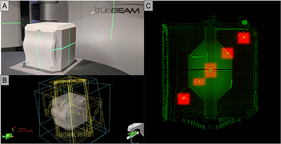
Figure 5. Implementation of the OneIso phantom on a Varian TrueBeam linac with HD-MLCs. (A) 3D printed phantom. (B) Eclipse treatment plan portal fields. (C) Overlap of DRR and treatment portal images for one field (gantry = 270∘, collimator = 0∘, table = 0∘).
Download figure:
Standard image High-resolution image
Figure 6. Image processing analysis of DRR and treatment portal images. (A) The OneIso phantom containing a row of off-axis BBs lateral direction. (B) Eclipse treatment plan portal for one field (gantry = 90∘, collimator = 0∘, table = 0∘), where the DRR and radiation treatment plan DICOM images are imported into MATLAB. (C) Analyzed DRR images, where the field and BB centers are indicated by blue circles and red crosses, respectively. (D) Analyzed portal images, where the field and the BB centers are indicated by blue and red circles, respectively. (E) Direct comparison of the planned and delivered BB locations.
Download figure:
Standard image High-resolution image3. Results
3.1. Ion chamber dosimetry
Two independent dosimetric measurement techniques were performed. Namely, pinpoint ion chamber measurements in the OneIso phantom (DOneIso) and pinpoint ion chamber measurements in an SW phantom (DSW). The percent dose difference between the dose calculated by the TPS (DTPS) and either DOneIso or DSW are listed in table 2. The average percent dose difference between DOneIso and DTPS and DSW and DTPS are −0.62% ± 0.31% and −0.19% ± 0.56%, respectively. The maximum percent dose difference between DTPS with either DOneIso or DSW is less than 3.5%. The standard deviation of the percent dose difference between ion chamber measurements and calculated dose ranges from 0.1–0.6% and 0.1–2.0% for OneIso and SW phantom measurements, respectively. OneIso and the SW phantoms agree within 1%, for both film and point dose measurements.
Table 2. The percent dose difference between the dose measured by ion chamber in either the OneIso phantom or SW phantom and dose calculated by the TPS, as well as the absolute difference between OneIso phantom and SW phantom percent differences with the TPS.
| Δ(DOneIso–DTPS)%† | |||||
|---|---|---|---|---|---|
| Day 1 | Day 2 | Day 3 | Average | SD | |
| Plan 1 | −1.41% | −1.97% | −2.30% | −1.89% | 0.45% |
| Plan 2 | 0.59% | −0.30% | −0.45% | −0.05% | 0.56% |
| Plan 3 | −2.35% | −2.25% | −2.63% | −2.41% | 0.20% |
| Plan 4 | −2.78% | −3.01% | −3.39% | −3.06% | 0.31% |
| Plan 5 | −0.50% | −0.58% | −1.21% | −0.76% | 0.39% |
| Plan 6 | −0.03% | −0.58% | −0.89% | −0.50% | 0.44% |
| Plan 7 | −0.36% | −0.51% | −0.94% | −0.60% | 0.30% |
| Plan 8 | −2.14% | −2.22% | −2.67% | −2.34% | 0.28% |
| Plan 9, Target 1 | −2.11% | −1.64% | −2.03% | −1.93% | 0.25% |
| Plan 9, Target 2 | −1.67% | −1.44% | −1.58% | −1.56% | 0.11% |
| Plan 10, Target 1 | 2.04% | 1.71% | 1.96% | 1.90% | 0.17% |
| Plan 10, Target 2 | 2.92% | 2.26% | 2.87% | 2.68% | 0.37% |
| Plan 10, Target 3 | 2.50% | 2.60% | 2.27% | 2.46% | 0.17% |
| Average: | −0.62% | 0.31% | |||
| Δ(DSW–DTPS)%† | |||||
| Day 1 | Day 2 | Day 3 | Average | SD | |
| Plan 1 | 0.49% | −0.15% | 1.42% | 0.59% | 0.79% |
| Plan 2 | 1.85% | 0.67% | 0.62% | 1.05% | 0.70% |
| Plan 3 | −1.99% | 1.71% | −1.35% | −1.68% | 0.32% |
| Plan 4 | −3.35% | −2.63% | 0.36% | −1.87% | 1.97% |
| Plan 5 | 0.94% | 0.72% | 1.60% | 1.09% | 0.46% |
| Plan 6 | 0.26% | 0.03% | 0.57% | 0.29% | 0.27% |
| Plan 7 | −0.01% | 0.02% | 1.27% | −0.42% | 0.73% |
| Plan 8 | −1.53% | −2.01% | −3.28% | −2.27% | 0.90% |
| Plan 9, Target 1 | −3.34% | −2.27% | −3.53% | −3.21% | 0.39% |
| Plan 9, Target 2 | −1.91% | −1.76% | −2.08% | −1.92% | 0.16% |
| Plan 10, Target 1 | 1.75% | 1.63% | 2.17% | 1.85% | 0.28% |
| Plan 10, Target 2 | 2.64% | 2.77% | 2.60% | 2.67% | 0.08% |
| Plan 10, Target 3 | 1.12% | 1.53% | 1.38% | 1.34% | 0.21% |
| Average: | −0.19% | 0.56% | |||
| |Δ(DSW–DTPS)%-Δ(DOnelso–DTPS)%| | |||||
| Day 1 | Day 2 | Day 3 | Average | SD | |
| Plan 1 | 1.90% | 1.82% | 3.72% | 2.48% | 1.08% |
| Plan 2 | 1.26% | 0.97% | 1.07% | 1.10% | 0.15% |
| Plan 3 | 0.36% | 0.54% | 1.27% | 0.72% | 0.49% |
| Plan 4 | 0.57% | 0.38% | 3.75% | 1.57% | 1.89% |
| Plan 5 | 1.44% | 1.30% | 2.81% | 1.85% | 0.84% |
| Plan 6 | 0.29% | 0.61% | 1.47% | 0.79% | 0.61% |
| Plan 7 | 0.36% | 0.52% | 0.33% | 0.40% | 0.10% |
| Plan 8 | 0.61% | 0.21% | 0.61% | 0.48% | 0.24% |
| Plan 9, Target 1 | 1.23% | 1.13% | 1.50% | 1.28% | 0.19% |
| Plan 9, Target 2 | 0.23% | 0.32% | 0.50% | 0.35% | 0.14% |
| Plan 10, Target 1 | 0.29% | 0.08% | 0.21% | 0.19% | 0.10% |
| Plan 10, Target 2 | 0.29% | 0.51% | 0.26% | 0.35% | 0.13% |
| Plan 10, Target 3 | 1.38% | 1.07% | 0.89% | 1.11% | 0.25% |
| Average: | 0.98% | 0.48% | |||
SD: standard deviation; †Pinpoint ion-chamber measurements in OneIso phantom (DOneIso), pinpoint ion chamber measurements in an SW phantom (DSW), and the dose calculated by the TPS (DTPS).
3.2. Radiochromic film dosimetry
Figure 7 shows a representative film comparison example of film measurements performed for one of the plans. Qualitatively, both OneIso and SW phantom produced similar dose distributions as those determined by the TPS. Quantitatively, the gamma passing rate for OneIso (γ(FilmOneIso)) and SW phantom (γ(FilmSW)) were 99.9% and 100.0%, respectively. The gamma passing rate for OneIso and SW phantom are listed in table 3. The average gamma passing rate across all plans for OneIso and SW phantom are 98.6% ±1.7% and 99.3% ± 1.4%, respectively. The maximum percent difference between γ(FilmSW) and γ(FilmOneIso) is less than 2.2%.
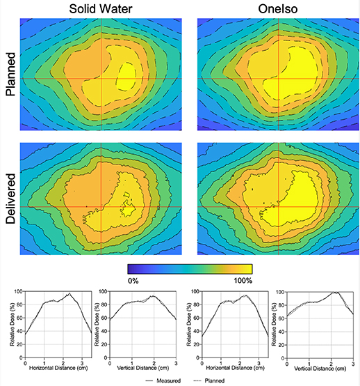
Figure 7. Film measured in SW (γ(FilmSW) = 100.0%) and OneIso (γ(FilmOneIso) = 99.9%) for a representative patient. The color bar indicates the isodose percent lines from 0% to 100% of the dose. Red lines indicate the vertical and horizontal relative dose profiles.
Download figure:
Standard image High-resolution imageTable 3. The gamma passing rate (γ) between the dose measured by film in either the OneIso phantom or SW phantom and the dose calculated by the TPS.
| γ(FilmOneIso)%† | γ(FilmSW)%† | Difference | |
|---|---|---|---|
| Plan 1 | 100.0% | 100.0% | 0.1% |
| Plan 2 | 94.2% | 95.1% | 0.9% |
| Plan 3 | 99.2% | 99.7% | 0.4% |
| Plan 4 | 98.3% | 98.8% | 0.5% |
| Plan 5 | 98.9% | 99.9% | 1.0% |
| Plan 6 | 97.5% | 99.7% | 2.2% |
| Plan 7 | 96.6% | 98.8% | 2.2% |
| Plan 8 | 99.9% | 100.0% | 0.1% |
| Plan 9, Target 1 | 100.0% | 100.0% | 0.0% |
| Plan 9, Target 2 | 100.0% | 100.0% | 0.0% |
| Plan 10, Target 1 | 99.0% | 100.0% | 1.0% |
| Plan 10, Target 2 | 99.0% | 98.3% | −0.7% |
| Plan 10, Target 3 | 99.0% | 100.0% | 1.0% |
| Average (SD): | 98.6 (1.7)% | 99.3 (1.4)% | 0.7 (0.9)% |
SD: standard deviation. The difference was determined by calculating the percent difference between the two gamma passing rate: (γ(FilmSW)%—γ(FilmOneIso)%)/γ(FilmSW)%. †Film measurements in OneIso phantom (FilmOneIso) and film measurements in an SW phantom (FilmSW) compared with the dose distribution calculated by the TPS using FilmQA Pro software (Ashland Advanced Materials, Bridgewater, NJ).
Figure 8 shows a film measurement performed on a plan with non-zero couch angles and multiple targets using OneIso. OneIso's central drum was rotated 45∘ to capture both targets on one film. Quantitatively, OneIso gamma passing rate was 100.0%. Alternatively, using SW, two film measurements were performed to capture the same information as one film measurement using OneIso.
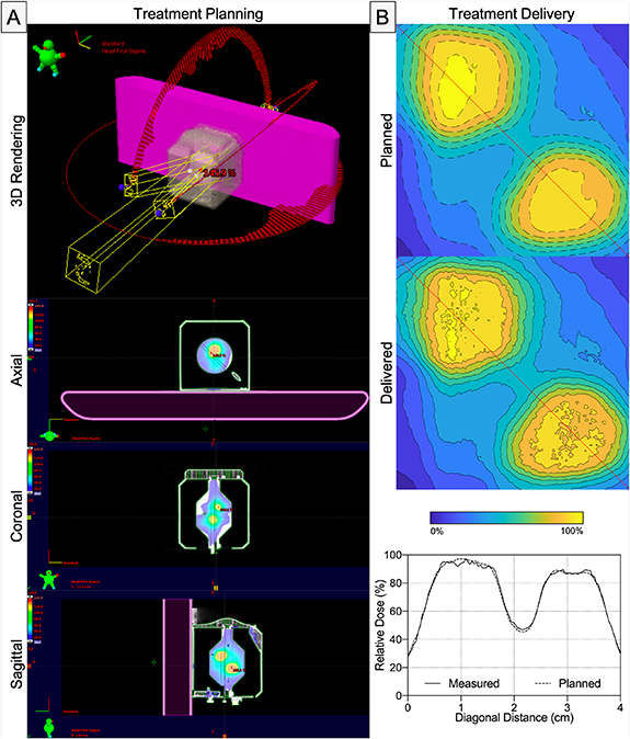
Figure 8. (A) A patient specific QA plan generated from film measurement for a multitarget plan that includes non-zero couch angles, where the OneIso's film insert was rotated to 45∘ to capture both targets. (B) Film measured in the OneIso (γ(FilmOneIso) = 100.0%) for the delivered plan. The color bar indicates the isodose percent lines from 0% to 100% of the dose. Red lines indicate the diagonal relative dose profile that cuts through both targets.
Download figure:
Standard image High-resolution image3.3. Off-axis Winston-Lutz test
OneIso identified a reduction in spatial accuracy further away from isocenter. Figure 9(A) shows the spatial accuracy as a function of distance from the isocenter, illustrating that the spatial accuracy reduces further away from isocenter. On average, the differences increased as distance from isocenter increased (slope = 0.004 ± 0.002), exceeding recommended SRS accuracy tolerances of 1 mm (Halvorsen et al 2017) at 7 cm away from isocenter. Table 4 lists for each collimator, gantry, and table angle to avoid specific beam angles which are out of the 1 mm tolerance. To validate our in-house software, the average difference between our analysis and commercial Winston-Lutz software was less than 0.02 mm for the central BB. Furthermore, we tested the robustness of the analysis—where we physically shifted the phantom a known amount and recovered the offset in the analysis pipeline (figure 9(B): physical offset vs measured offset, slope =1.14 ± 0.32).
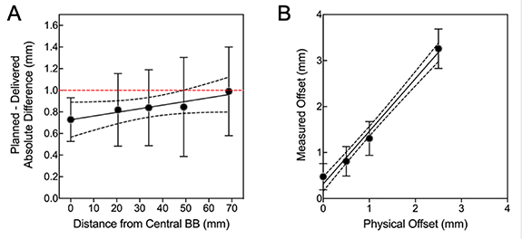
Figure 9. The quantitative Winston-Lutz 2D displacements (A) for off-axis BB locations (slope = 0.004 ± 0.002) and (B) demonstrating the robustness of the analysis by shifting the phantom and recovering the shifts (offsets) (physical offset vs measured offset, slope = 1.14 ± 0.32). Points = mean; error-bars = standard-deviation; line = linear-regression; dotted-lines = 95% confidence-interval; red-dashed line = 1 mm Winston-Lutz threshold.
Download figure:
Standard image High-resolution imageTable 4. The quantitative Winston-Lutz 2D displacements for off-axis BB locations at each collimator, gantry, and table angle.
| BB Locations Relative to Isocenter (mm) | |||||
|---|---|---|---|---|---|
| C/G/T | 0 mm | 2 mm | 3.5 mm | 5 mm | 7 mm |
| C1: 0∘/90∘/0∘ | 0.49 | 0.58 | 0.60 | 0.36 | 1.64 |
| C2: 0∘/45∘/0∘ | 0.60 | 0.97 | 0.59 | 0.96 | 1.04 |
| C3: 0∘/315∘/0∘ | 1.13 | 1.12 | 1.04 | 1.55 | 0.87 |
| C4: 0∘/270∘/0∘ | 0.84 | 1.24 | 1.03 | 0.94 | 0.94 |
| G1: 270∘/0∘/0∘ | 0.49 | 0.21 | 0.47 | 0.44 | 0.44 |
| G2: 0∘/0∘/0∘ | 0.84 | 1.04 | 0.89 | 1.17 | 1.01 |
| G3: 90∘/0∘/0∘ | 0.55 | 0.58 | 1.12 | 1.04 | 0.47 |
| G4: 180∘/0∘/0∘ | 0.52 | 0.29 | 0.48 | 0.51 | 0.68 |
| T1: 0∘/0∘/90∘ | 0.74 | 1.16 | 1.67 | 1.06 | 0.72 |
| T2: 0∘/0∘/45∘ | 0.87 | 1.03 | 0.91 | 1.52 | 0.91 |
| T3: 0∘/0∘/315∘ | 0.88 | 0.88 | 0.75 | 0.47 | 1.41 |
| T4: 0∘/0∘/270∘ | 0.80 | 0.69 | 0.51 | 0.17 | 1.69 |
| Average (SD): | 0.73 (0.20) | 0.82 (0.34) | 0.84 (0.35) | 0.85 (0.45) | 0.99 (0.41) |
C: collimator; G: gantry; T: table; SD: standard deviation.
4. Discussion
Frameless linac-based non-coplanar SRS treatments are increasingly being used in conjunction with optical surface monitoring systems. These open mask-based frameless SRS treatments have been shown to have outcomes equivalent to frame based systems (Kamath et al 2005, Breneman et al 2009, Minniti et al 2011), and provide fast treatments when combined with FFF x-ray beams on modern medical linacs. The integrated phantom in this study provides a streamlined single-setup workflow solution for SIMT frameless linac-based SRS QA. This single setup allows independent verification of all positioning systems, both ion chamber point dose and film measurements, as well as determination of spatial accuracy as a function of distance from isocenter. This integrated approach provides accurate coincidence verification, with reduced chance of setup errors. The proposed SRS QA workflow using this phantom for SRS treatment involves eight steps (supplementary video illustrating the process available at stacks.iop.org/PMB/65/115006/mmedia): (i) Place the phantom on the couch with BB at isocenter. (ii) Use kV-kV match to shift the phantom to isocenter. (iii) Verify the phantom position with MV-MV match and CBCT image. (iv) Simultaneously perform Winston-Lutz, off-axis Winston-Lutz, and optical surface monitoring system tests (vary couch, collimator, and gantry angles). (v) Slide the ion chamber to isocenter position with the insert. (vi) Measure the charge by delivering the treatment plan. (vii) Replace ion chamber insert with film insert. (viii) Deliver the treatment plan on film for further analysis.
In this work, an integrated phantom which encompasses QA of the positioning systems and dose measurements without re-aligning the phantom is presented. Although other phantoms exist that each cover a subset of these systems, only one commercially available solution covers all these positioning systems (Ramani et al 1995, Sarkar et al 2016, Dimitriadis et al 2017, Yu et al 2018, Poder et al 2018). The OneIso phantom, however, removes the problems associated with multiple setups. The optimized size and design of the OneIso phantom also means that micro ion chambers (<0.02 cm3) are easily visible on planar imaging, which is not the case with standard SW phantoms, as the size often results in a very low contrast to noise ratio.
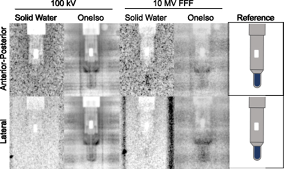
Ion chamber dose measurements with the OneIso phantom and SW phantom agreed within 3.5% of the TPS. One weakness of a single point dose measurement is that it may become unreliable in regions of steep dose gradient. It should be noted that no issues were observed for the 15 mm3 pinpoint ion chamber when combined with a minimum planning target volume diameter of 8 mm used in this work. Smaller targets or steeper dose gradients may require a smaller detector such as the Exradin W1 (2 mm3 active volume). Also, applying a known shift to ensure the measured point is in a low-gradient region has been shown to be effective in making point dose measurements more reliable (Kumar et al 2007). Additionally, the wider spread of ion chamber dose measurements with the SW phantom compared to that with OneIso phantom are most likely due to the low visibility of the small ion chamber cavity inside the large SW phantom, which adds setup uncertainty. The smaller water equivalent path length (6–6.5 cm) through the cylindrical portion of the OneIso phantom provides easier setup verification using images as the smaller size means less scatter and higher contrast than a 30 × 30 × 20 cm3 phantom. We attribute the lower uncertainty of ion chamber dosimetry results using the OneIso phantom compared to a standard SW phantom to the improved alignment accuracy. As shown in figure 10, the ion chamber is easier to locate with both kV and MV imaging which is due to the optimized thickness of the OneIso phantom. For dose measurements of the SRS plan, it is ideal to position the ion chamber with the energy used for the treatment plan, so the ion chamber is at the true therapeutic beam isocenter. However, due to the low visibility of the ion chamber in the SW phantom, it is commonly positioned with kV imaging and one must rely on establishing the imaging and delivery coincidence with another QA procedure.
Figure 10. Images of a pinpoint ion chamber with 100 kV (left) and 10 MV FFF (center) inside an SW phantom and the OneIso phantom as well as the reference (right) indicate where the active volume of the ion chamber is located (blue). Each image has the same exposure settings. The high noise is a result of the large thickness of the SW phantom (30 cm lateral and 20 cm anterior-posterior). The OneIso phantom, however, is cylindrical and has only 3 cm water equivalent buildup and backscatter.
Download figure:
Standard image High-resolution image
Gamma passing rate percent difference between OneIso phantom and SW phantom agreed within 0.7 ± 0.9%. The disagreement between OneIso and SW film measurements might be due to the positional inaccuracy and the uncertainty of the film dosimetry. While radiochromic films such as EBT2 and EBT3 are highly valuable for their high spatial resolution, accurate dosimetry is more difficult. Even with optimal control of humidity, temperature, wait time, and scanner, due to the film inhomogeneities, a two sigma uncertainty of ±4% is expected (Girard et al 2012). The stability and well characterized dose-response of micro ion chambers means that they can provide a volume averaged data point with significantly higher certainty (Huq et al 1997, Rogers 1998, Tailor et al 1998) assuming accurate positioning. Our method has comparable percent dose error and gamma analysis in a recent study that investigated the combination of SRS MapCHECK device within the StereoPHAN phantom (Sun Nuclear), albeit the device is limited for cases with certain beams angles (Ahmed et al 2019).
Paramount to implementing a single-isocentric approach is quantifying the spatial accuracy of targets as a function of distance away from isocenter to ensure proper margins are allocated to targets further away from isocenter so that targets receive proper dosimetric coverage. However, rigorous QA measurements have not been performed to evaluate the off-axis accuracy of a linac, which is critical in facilitating the translation of a single-isocentric approach to treat multiple lesions. While exhaustive methods have been proposed to quantify and establish acceptance measurements (Ezzell 2017), these processes can be extremely time consuming (involving manual identification via Offline Review) and subject to inter- and intra- user variability. Moreover, there is no standard on how to perform off-axis accuracy analysis, and results can be dependent on both the analysis and the phantom design, complicating the selection. To date, there is no standardized QA phantom specifically designed to quantify the spatial accuracy of a linac as a function of distance from isocenter, albeit one commercial vendor has recently marketed a solution (StereoPHAN MultiMet-WL Cube, Sun Nuclear). Multiple solutions have previously been investigated in the research setting (Gao and Liu 2016, Wen et al 2016, Ezzell 2017). The common attribute that all the previous phantoms possess is having a known geometry where markers are placed a specified distance away from isocenter. The markers are used to delineate potential targets for generating treatment plans, similar to the Winston-Lutz test, to evaluate any discrepancy between prescribed (DRR) and delivered (treatment portal) images. Rotation of either the couch, collimator, or gantry is performed to identify any misalignment with the radiation and mechanical isocenter. Previous studies have reported that misalignment increases with increasing distance from isocenter quantified using the offset between the center of the target in the DRRs and that in the portal images (Gao and Liu 2016, Ezzell 2017). Here, we designed and developed a phantom that not only has the ability to determine the uncertainty in spatial accuracy as a function of distance from isocenter, but also have the ability to perform QA on multiple image-guidance systems (i.e. kV, MV, CBCT, and optical surface tracking) for frameless treatments (Yu et al 2018). We developed the image processing software necessary to robustly quantify spatial accuracy to easily produce metrics for commissioning and performing QA for frameless SIMT SRS treatments. Our observations in combination with recommendations by the American Association of Physicists in Medicine (AAPM) (Klein et al 2009, Benedict et al 2010) and American Society for Radiation Oncology (ASTRO) (Potters et al 2010, Solberg et al 2012) for a Winston-Lutz test passing criteria of 1 mm agree with previous findings that an off-axis distance of 7 cm should be the limit (Ezzell 2017), specifically for the SRS machine we acquired and performed our analysis on. These results are corroborated with recent work demonstrating the tolerance for collimator and gantry angle, based on AAPM's Task Group 142 report (Klein et al 2009), are likely not suitable for linac based multitarget radiosurgery (Faught et al 2016).
The OneIso provides improved positioning verification and accurate dosimetry suitable for SRS QA measurements critically needed to commission a frameless SIMT cranial SRS program. This phantom and associated image analysis software will facilitate the commissioning and periodic QA of a multitarget frameless VMAT radiosurgery program, where specific metrics can be reliably reproduced, enabling clinical translation of this highly sought-after workflow solution.
Conflicts of interest
The authors have a provisional patent for this work. Dr Capaldi receives funding support from the American Association of Physicists in Medicine (AAPM) Seed Grant Award. All other authors declare no financial or other relationships which may lead to a conflict of interest.