
Abstract
Small animal x-ray irradiation platforms are expanding the capabilities and future pathways for radiobiology research. Meanwhile, proton radiotherapy is transitioning to a standard treatment modality in the clinician's precision radiotherapy toolbox, highlighting a gap between state-of-the-art clinical radiotherapy and small animal radiobiology research. Comparative research of the biological differences between proton and x-ray beams could benefit from an integrated small animal irradiation system for in vivo experiments and corresponding quality assurance (QA) protocols to ensure rigor and reproducibility. The objective of this study is to incorporate a proton beam into a small animal radiotherapy platform while implementing QA modelled after clinical protocols.
A 225 kV x-ray small animal radiation research platform (SARRP) was installed on rails to align with a modified proton experimental beamline from a 230 MeV cyclotron-based clinical system. Collimated spread out Bragg peaks (SOBP) were produced with beam parameters compatible with small animal irradiation. Proton beam characteristics were measured and alignment reproducibility with the x-ray system isocenter was evaluated. A QA protocol was designed to ensure consistent proton beam quality and alignment. As a preliminary study, cellular damage via γ-H2AX immunofluorescence staining in an irradiated mouse tumor model was used to verify the beam range in vivo.
The beam line was commissioned to deliver Bragg peaks with range 4–30 mm in water at 2 Gy min−1. SOBPs were delivered with width up to 25 mm. Proton beam alignment with the x-ray system agreed within 0.5 mm. A QA phantom was created to ensure reproducible alignment of the platform and verify beam delivery. γ-H2AX staining verified expected proton range in vivo.
An image-guided small animal proton/x-ray research system was developed to enable in vivo investigations of radiobiological effects of proton beams, comparative studies between proton and x-ray beams, and investigations into novel proton treatment methods.
Export citation and abstract BibTeX RIS

Original content from this work may be used under the terms of the Creative Commons Attribution 3.0 licence. Any further distribution of this work must maintain attribution to the author(s) and the title of the work, journal citation and DOI.
Introduction
Protons have shown their effectiveness in clinical radiotherapy, being applied in the treatment of diseases including medulloblastoma (Giantsoudi et al 2016, Kopecky et al 2017), hepatocellular carcinoma (Chiba et al 2005, Igaki et al 2017), uveal melanoma (Gragoudas and Marie 2005), prostate cancer (Iwata et al 2018), and non-small cell lung cancer (Ono et al 2018), among others. Many of the existing studies comparing proton and x-ray therapy including complex system-wide biological responses (Girdhani et al 2013) in targets with proton therapy entail retrospective clinical studies (Chiba et al 2005, Gragoudas and Marie 2005, Giantsoudi et al 2016, Igaki et al 2017, Iwata et al 2018, Ono et al 2018) and a number of in vitro cell studies (Kraft et al 2010, Sørensen et al 2011, Yu et al 2017). Pre-clinical in vivo studies for both proton (Kondo et al 2015, Girst et al 2016) and heavy ions (Peschke et al 2011, Saager et al 2014); however, have proven to be relatively rare in the published literature.
There are a limited number of systems in use to conduct small animal image-guided x-ray studies (Ford and Deye 2016, Verhaegen et al 2017) with commercial products such as the small animal radiation research platform (SARRP) from Xstrahl Inc. and the X-RAD 225Cx from Precision x-ray Inc. However, there are fewer systems (Datzmann et al 2001, Kraft et al 2010, Greubel et al 2011, Ford et al 2017) in operation for small animals with imaging capabilities available for in vivo proton studies. Some of the existing systems use pulsed microbeams (Datzmann et al 2001, Kraft et al 2010), which show different characteristics from proton beams generated from clinical accelerators (Kraft et al 2010). University of Washington in Seattle, WA has developed a system (Ford and Deye 2016, Ford et al 2017) which couples the SARRP with a proton beamline previously used for neutron therapy, demonstrating the feasibility of developing an image-guided small animal proton research platform in a clinical setting. However, a protocol for rigorous and robust system QA and reference dosimetry has not been consistently applied across pre-clinical proton irradiators. This is an issue not confined to pre-clinical proton radiobiology, but nevertheless complicates cross-institutional analysis of comparative results.
This study discusses the design and commissioning experience of a SARRP coupled with the clinical proton beamline at the University of Pennsylvania Roberts Proton Therapy Center in Philadelphia, PA. A QA protocol was developed specifically for the coupled x-ray/proton small animal radiation system, expanding on the protocols developed by other groups for image-guided x-ray/proton radiation platforms (Brodin et al 2015, Jermoumi et al 2015).
Methods and materials
Beam line design
The Roberts Proton Therapy Center at the University of Pennsylvania consists of the IBA Proteus Plus with a C230 cyclotron (IBA Proton Therapy, Louvain-La-Neuve, Belgium), five clinical treatment rooms (four gantry and 1 fixed beam) and a sixth dedicated research room with two fixed beam lines, herein designated RA6 and RA7. The C230 cyclotron and energy selection system (ESS) can modulate the beam energy in terms of water equivalent thickness (WET) from a maximum energy of 230 MeV (approx. 33 cm WET) to a minimum energy of approximately 70 MeV (approx. 4.1 cm WET). To reduce the range of the proton beam to be useful in small animal models, an additional 4 cm WET range shifter was added to the end of the RA7 beamline.
The SARRP is installed on rails (figure 1(a)) in the shielded research room allowing movement into and out of the RA7 beam path. The integrated SARRP shielding was removed to make loading of animals easier. A remotely operated anesthesia system and multiple video camera views were installed for safely monitoring animal status. The SARRP was mounted on rails so that the imaging capabilities and robotic positioning stage can be shared with the proton beam system providing the capability to use the on-board CBCT for imaging small animals with proton studies. The ability for the SARRP to move in an out of the proton beam, by sliding it along the rails, allows for versatile use of the proton beam with larger equipment, such as water tanks and scintillation detectors, that would not fit on the SARRP stage. By removing the SARRP from the beam path, measurement can easily be made for commissioning and QA procedures. At installation, the SARRP stage was levelled with height adjustable pedestals connecting the SARRP frame to the sliding rail platform. Furthermore, positioning of the SARRP stage, gantry, and rails were designed to be square with the proton beam line to reduce any rotational uncertainty and requiring correction of translational shifts only.

Figure 1. (a) Photo of SARRP-on-rails for movement in and out of the proton beam line. The beam line RA6 in the foreground is not used with the SARRP. The RA7 beam line is visible to the right of the SARRP. (b) A schematic of the proton beam collimation system. Primary dosimetry IC1 chamber is installed at the end of the evacuated beam pipe followed by a 4 cm WET solid water plastic degrader. The secondary dosimetry IC2 follows, preceding the brass primary and secondary collimator with interchangeable final collimation installed on a collimator positioning stage with 2D planar translation, rotation, and tilt adjustments.
Download figure:
Standard image High-resolution imageA collimation system was designed to shape the proton field size for small animals. The design allows for use of interchangeable brass collimators with the proton beam. Using these collimators, a range of field sizes from 0.5 to 10 mm widths can be achieved. The collimation system is mounted on a movable platform at the end of the RA7 line, which allows for multiple degrees of freedom including translational movement, pitch, and tilt (figure 1(b)) so that the collimator can be optimally aligned with the proton beam at any position.
Beam characteristics
The IBA Zebra device (IBA Dosimetry, Bartlett TN) was used to measure the percent depth dose (PDD) for a range of energies from 77 MeV to 96 MeV with 0.55 mm resolution (figure 2(a)). The intrinsic resolution of the Zebra detector is 2.0 mm but 1.0 mm resolution is attainable by repeating measurements with a 1.0 mm window inserted. Higher resolution with the Zebra device was achieved using paper index cards. The WET of a stack of 50 cards was first determined. Then a group of five cards (corresponding to 0.55 mm WET) was placed in front of the detection chamber. Data was merged with the corresponding 0.55 mm WET shift from the index cards, 1 mm WET window, and measurement with no WET shift.

Figure 2. Depth dose curves for a range of requested energies (77–96 MeV) with a 5 mm × 5 mm square collimated beam. (a) The IBA Dosimetry Zebra device was used and all curves were normalized relative to the maximum. (b) Zebra measurements were compared to water tank measurements using a PTW Bragg Peak chamber for a requested energy of 89 MeV (6.3 g cm−2 range) with 4 cm WET build up.
Download figure:
Standard image High-resolution imagePDD measurements were also taken using a PTW Bragg Peak Chamber (PTW, Freiburg, Germany) in an IBA 1D water tank (figure 2(b)). The scanning motor and track were mounted in the horizontal plane of the water tank parallel with the proton beam path, as opposed to the standard vertical orientation. The Bragg peak chamber was aligned with the proton beam using EBT3 GafChromic film (Ashland Advanced Materials, Bridgewater, NJ, USA) to verify the position of the proton beam. Measurements were taken in steps of 0.5 mm along the dose distribution. The measurement position was determined for the nominal beam configuration used for small animal irradiations, which includes a 4 cm WET degrader. For measurement of PDD in water, the Bragg peak chamber wall (4.11 mm) and the water tank wall (11.0 mm) with the addition of 2.5 cm of WET solid water were placed in the beam path for a resulting WET of 4.022 cm. The difference in WET between the measurements with the water tank set-up and the nominal beam (0.022 cm) was the shallowest measurement depth shown in figure 2(b).
In addition, lateral beam profiles were measured using EBT3 film for multiple energies and depths. The beam profiles were scanned using an Epson 1000XL flat-bed scanner and analyzed using ImageJ (NIH, Bethesda, MD, USA) and Matlab (version R2017b, MathWorks Inc., Natick, MA, USA) software. Flatness and symmetry were analyzed using the Varian definition with the data smoothed with a 10% span for the moving average.
Absolute dose measurements were performed with an Advanced Markus Chamber (PTW, Freiburg, Germany) according to International Atomic Energy Agency TRS-398 code of practice recommendations. The sensitive volume of the detector (2.5 mm radius) was placed in the middle of a spread out Bragg peak (SOBP), with distal range of 2.3 cm and modulation (width) of 1 cm, of the large uncollimated open field to mitigate volume averaging. The uncollimated open field has a Gaussian shape with a full width half max of 16.8 mm. The chamber was centered on the uncollimated beam and placed in the middle of the SOBP with 1.5 cm of solid water build up. EBT3 film response was calibrated using procedure described in Zhao and Das (2010) and Reinhardt et al (2012). Proton Bragg peak under response of around 20% has been observed for both EBT (Zhao and Das 2010) and EBT2/EBT3 film (Reinhardt et al 2012). To account for the intrinsic proton energy response characteristics of gafchromic film, the EBT3 films were cross-calibrated with the Markus chamber measurement of the uncollimated field at the same measurement depth to ensure a consistent proton energy spectrum for both film and ionization chamber measurements. It was assumed that the effect of scatter on output due to the collimation would be negligible so that the open field film calibration curve could be applied to film irradiated with collimated fields. Dose calculation for films used for dosimetry was performed using parameters from calibrated film of the same batch.
Quality assurance (QA) protocol
To ensure the reproducibility of studies between different systems, a QA program was developed to maintain the reliability and characteristics specific to each proton and x-ray system. A QA phantom was designed to hold two pieces of Gafchromic film: one at the front face to verify proton beam alignment and another in line with the beam direction to show the depth dose of a Bragg peak. Figure 3(a) shows the resulting QA phantom that was 3D printed at the University of Pennsylvania using a Form2 printer (Formlabs, Boston, MA, USA) and clear engineering resin. A small high-z material (aluminum of 1.2 mm in length) was affixed on the front face of the phantom to target upon CBCT acquisition.
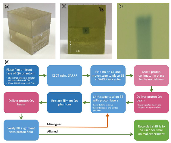
Figure 3. Design and use of the 3D printed QA phantom. (a) QA phantom, (b) alignment film with proton field centered on the high Z material BB, (c) longitudinal film to verify depth dose characteristics of the QA beam, (d) procedure for isocenter alignment QA.
Download figure:
Standard image High-resolution imageTable 1 shows the daily QA requirements to be checked prior to acquiring experimental data. This ensures accurate alignment of the proton beam with the SARRP isocenter and provides a check of the consistency of the beam characteristics as well as the safety interlocks. The front of the phantom, mentioned above, holds a 30 mm × 40 mm film (figure 3(b)). The two pieces fit together with another 30 mm × 40 mm film between them. The film between the two pieces is tilted at a 5° angle from the horizontal. This ensures that the depth dose profile is not unduly altered by the effects of an air gap between film and phantom. Zhao and Das (2010) found that EBT film placed parallel to a proton beam in a comparable phantom can be used to measure proton range with an uncertainty of 0.5 mm. This accuracy is sufficient for QA and well within the experimental uncertainties for most small animal research. Since the film sits at an angle relative to the horizontal, the position on the film is slightly longer than the depth the proton beam traveled. Each position on the film corresponds to a specific depth in the phantom, however, through the relation R = f · cos(5°) where R represents the depth the proton beam traveled and f represents the distance between the front end of the film and the point of interest on the film. An example of the depth dose profile from the film is shown in figure 3(c).
Table 1. Daily QA requirements. All items must be tested prior to beam delivery for an experiment.
| Procedure | Tolerance |
|---|---|
| Dosimetry | |
| Flatness | 5% of baseline |
| Symmetry | 5% of baseline |
| Range | 1 mm from baseline |
| Depth dose profile | 2% of baseline |
| Mechanical | |
| SARRP laser localization | 1 mm |
| X-ray laser localization | 1 mm |
| Proton beam alignment with SARRP isocenter | <0.5 mm |
| Robotic stage shift | <5 mm |
| Imaging | |
| CBCT functionality | Functional |
| Safety | |
| Beam disable | Functional |
| DCEU beam shut Off | Functional |
| Video/audio monitoring | Functional |
| Room search | Functional |
| Door interlock | Functional |
| Door warning lights | Functional |
| In-room radiation detectors | Functional |
| Audible radiation alarm | Functional |
The alignment protocol process is shown in figure 3(d). After the SARRP is placed in the proton beam path, the QA phantom can be placed on the SARRP animal positioning stage. A CBCT of the phantom is then acquired. The high-z material in the phantom is easily visible in the image. The center of the high-z material is identified and the robotic stage is moved so that the SARRP isocenter is placed at the high-z material. A proton field is then delivered with collimation. Figure 2(b) shows alignment with a 5 × 5 mm2 collimator, but a smaller collimator can be used for more accurate alignment. After the proton field is delivered, the necessary shift between the high-z material and the center of the proton field (determined by ImageJ) is recorded. The shift and collinearity of the SARRP mechanical and imaging isocenters is then verified with delivery of a second proton beam onto a second piece of film and after the robotic animal stage shift is performed.
Tumor irradiation and γ-H2AX immunofluorescence staining
A 5 × 5 mm2 collimator was used to deliver an 89 MeV (6.3 g cm−2) beam to flank tumor on a C57BL/6 mouse to a dose of 4 Gy. 2 cm WET of bolus was placed in front of the target so that the Bragg peak would be located within the tumor at 3 mm depth. Optimal cutting temperature OCT compound embedded B16F10 tumor tissues were processed and stained for DNA double strand breaks as described previously (Verginadis et al 2017).
Results
Percent depth dose (PDD)
PDDs are shown for each measured energy in figure 2. Energies from 77 MeV to 96 MeV, with 2–4 MeV steps, were measured with the IBA Zebra device and a 4 cm range shifter at the end of the beam pipe. A 0.11 mm resolution with a minimum measurement depth of 1.9 mm was achieved with the Zebra device. Data shown in figure 2 does not include under- or over-responding ionization chambers in the Zebra device. Table 2 gives more specific information for the 90% peak width, 90% dose range, and the ratio of entrance (1.9 mm depth) to peak readings. The minimum measurement depth can be further decreased by removing the Bragg Peak chamber (3 mm WET) that was installed between the collimator and the beam pipe. This Bragg Peak chamber will be used for online verification of dose delivery. For each energy, the distal dose falls to <10% of its peak within 2 mm.
Table 2. Depth Dose Profile Information for a 5 mm × 5 mm collimated beam.
| Requested beam energy (MeV) | Distal 90%—proximal 90% width (mm) | Distal 90% depth (mm) | 80%–20% fall-off distance (mm) | Entrance dose/peak dose ratio (%) |
|---|---|---|---|---|
| 96 | 2.50 | 30.51 | 1.79 | 46.99 |
| 94 | 2.08 | 27.43 | 1.69 | 48.24 |
| 91 | 1.80 | 23.24 | 1.83 | 47.87 |
| 89 | 2.59 | 21.68 | 1.38 | 50.79 |
| 87 | 1.38 | 18.31 | 1.60 | 49.50 |
| 85 | 2.06 | 15.39 | 1.45 | 55.08 |
| 82 | 1.81 | 12.37 | 1.51 | 58.00 |
| 80 | 1.12 | 8.89 | 1.61 | 66.50 |
| 77 | 0.88 | 5.96 | 1.45 | 88.58 |
With the range of energies available for this system, a spread-out Bragg peak (SOBP) can be created and delivered. This is done by pre-determining the number of monitor units required for each energy and stopping the beam when that limit is reached. Unique SOBPs can be created for each experiment. The range of the SOBP is limited by the range of the highest energy beam involved. SOBPs with a range of 29.5 mm and width of 24 mm to a range of 8.4 mm and width of 2.9 mm have been commissioned. Pristine Bragg peak weighting to generate an SOBP can be calculated with in-house software developed in Matlab. Figure 4 shows the calculated versus measured SOBP. Generally, the measured SOBP exhibits lower dose relative to the maximum value than the calculated SOBP. The beam delivery system limits the accuracy of beam weighting to 10 monitor units (MU). The calculated SOBP has weighted individual monoenergetic Bragg peaks with higher precision, and during delivery, these weights were rounded to the nearest 10 MU.
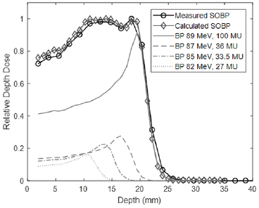
Figure 4. An SOBP was generated, delivered, and measured using the Zebra device. The expected depth dose curve is also shown.
Download figure:
Standard image High-resolution imageLateral beam profiles
The lateral beam profile in the x and y direction (horizontal and vertical directions, respectively) for a 3 mm × 3 mm and 5 mm × 5 mm collimated beam at multiple depths in a solid water phantom placed on the SARRP stage is shown in figure 5. As expected, the FWHM of the beam profile began to increase slightly with depth from 0 mm depth to 9.8 mm depth and is summarized in table 3. Lateral profiles were determined from film scanned and analyzed for relative density using ImageJ. Film was placed between thin pieces of solid water to determine the lateral profile for multiple depths using the same beam.
Table 3. FWHM and lateral penumbra (80%–20%) of profiles determined from film irradiation with requested beam energy 89 MeV (6.3 g cm−2 range) in the x- and y -directions for two collimators as a function of depth in solid water.
| x-profile | y-profile | x-profile | y-profile | ||
|---|---|---|---|---|---|
| Depth (mm) | FWHM (mm) | Lateral Penumbra (mm) | |||
| 3 × 3 mm2 | 0 | 2.63 | 2.60 | 0.10–0.12 | 0.15–0.10 |
| Collimator | 4.8 | 2.66 | 2.65 | 0.17–0.19 | 0.19–0.18 |
| 9.8 | 2.71 | 2.71 | 0.34–0.40 | 0.38–0.31 | |
| x-profile | y-profile | x-profile | y-profile | ||
| Depth (mm) | FWHM (mm) | Lateral Penumbra (mm) | |||
| 5 × 5 mm2 | 0 | 4.46 | 4.43 | 0.11–0.14 | 0.12–0.13 |
| Collimator | 4.8 | 4.50 | 4.48 | 0.18–0.20 | 0.18–0.18 |
| 9.8 | 4.61 | 4.61 | 0.37–0.35 | 0.38–0.36 | |
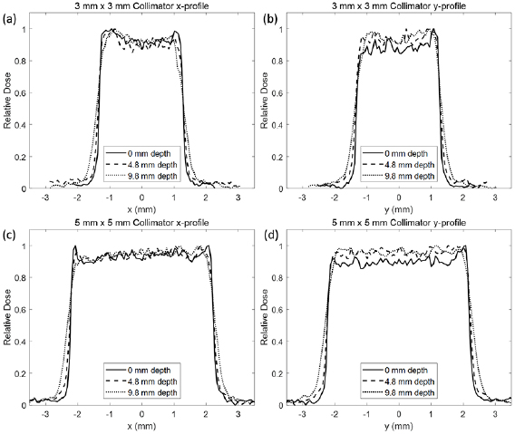
Figure 5. Lateral beam profile with a requested beam energy of 89 MeV (6.3 g cm−2) shown with the 3 × 3 collimator in the (a) x-direction, (b) y -direction and the 5 × 5 collimator with the (c) x-direction and (d) y -direction. Profiles were measured at depths of 0, 4.8, and 9.8 mm. A generally flat and symmetric profile can be obtained but a deviation can indicate collimator misalignment with the beam.
Download figure:
Standard image High-resolution imageFlatness and symmetry data are summarized in table 4. The y profile shows that a generally flat and symmetric distribution is achievable with the system. The x profile, however, shows a slightly higher degree of asymmetry. Collimator size also affects the flatness and symmetry measured. The 5 × 5 mm2 field sizes improved flatness and symmetry values (<6%) compared to the 3 × 3 mm2 field sizes (<12%). Increased field asymmetry can indicate a slight misalignment between the proton beam and the collimator. If the collimator is tilted with respect to the beam axis, the beam can be partially scattered, resulting in a tilted profile. This effect is used in the QA protocol to check the alignment of the collimator. The current collimator mounting system benefits from having finely tunable stages; however, it is easily susceptible to movement due to external forces or movement of the collimator in and out of position along the beam axis for clearance when moving the SARRP on its rails. Furthermore, analysis of flatness and symmetry can be limited for small field sizes and film profiles.
Table 4. Flatness and symmetry of profiles determined from film irradiation with requested beam energy 89 MeV (6.3 g cm−2 range) in the x- and y -directions for two collimators as a function of depth in solid water.
| 3 × 3 mm2 | x-profile | y -profile | ||
|---|---|---|---|---|
| Depth (mm) | Flatness (%) | Symmetry (%) | Flatness (%) | Symmetry (%) |
| 0 | 4.6 | 9.6 | 6.6 | 13.6 |
| 4.8 | 5.1 | 10.4 | 4.2 | 7.8 |
| 9.8 | 5.1 | 7.1 | 6.0 | 7.1 |
| 5 × 5 mm2 | x-profile | y -profile | ||
| Depth (mm) | Flatness (%) | Symmetry (%) | Flatness (%) | Symmetry (%) |
| 0 | 3.8 | 4.6 | 2.5 | 4.3 |
| 4.8 | 4.7 | 6.0 | 3.5 | 4.6 |
| 9.8 | 4.6 | 5.7 | 1.9 | 3.1 |
QA protocol
Using the QA phantom and protocol developed, the alignment shift between the SARRP isocenter and the proton beam center was determined both before and after shifting the robotic stage. By applying the robotic stage shifts, the discrepancy between the SARRP and the proton beam isocenters was improved from 2.67 ± 0.38 mm to 0.12 ± 0.04 mm (figure 6). The alignment and reproducibility were improved upon anchoring the x-ray SARRP in position against the rail stops. Without anchoring, the SARRP would drift to a slightly different position, resulting in larger discrepancies between the final x-ray-proton alignment (4.98 ± 2.15 mm pre-alignment to 1.46 ± 0.59 mm post-alignment). Example films from the protocol are shown in figures 3(b) and (c).
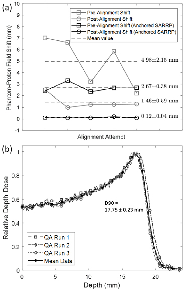
Figure 6. (a) Reproducibility and effectiveness of SARRP stage shift after isocenter alignment with the QA phantom. Prior to alignment, the difference between the QA phantom marker and the center of the proton field was found to be 4.98 ± 2.15 mm. After movement of the stage, the difference was reduced to be 2.67 ± 0.38 mm. Anchoring of the SARRP on the rail system improved the reproducibility and the final alignment to 0.12 ± 0.04 mm. (b) Multiple depth dose films from the QA phantom with a requested beam energy of 89 MeV (6.3 g cm−2) are compared to show reproducibility. Baseline film values can be used to verify the beam quality day-to-day. The mean depth of 90% was 17.75 ± 0.23 mm.
Download figure:
Standard image High-resolution imagePrior to any small animal experiments, this QA protocol should be performed to ensure that the beam quality is consistent and to determine the necessary shift between the CBCT isocenter and the proton field. After acquiring a CBCT of the small animal, the target is determined, and a shift of the robotic animal stage by the pre-determined amount from the QA protocol will ensure that the proton field is delivered accurately. The protocol takes 10–15 min depending on the beam availability and will be easy to implement prior to the day's experiments.
Cellular damage restriction to site of irradiation
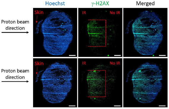
One of the main objectives of this study was to determine whether damage to the tumor tissue could be restricted to a specified depth using the data commissioned for the proton beam line and the QA protocol that was developed. A very well established method to analyze the direct damage post-irradiation is the detection of the phosphorylation of histone H2AX at serine 139 (γH2AX). This method is considered to be very sensitive and quantitative for detecting DNA-double strand breaks. Immunofluorescence staining for γH2AX on the B16F10 tumors harvested at 1 h after 4 Gy of proton irradiation showed that indeed the depth of the damage is restricted to 3 mm, corresponding to the depth of the Bragg peak set using energy selection and appropriate build-up (figure 7). Moreover, the width of the damaged area (around 4–5 mm) corresponds to the size of the 5 × 5 mm2 collimator used (figure 7), while the rest of the tissue has no visible DNA damage.
Figure 7. γH2AX immunofluorescence staining in OCT-frozen B16F10 tumor sections (200 µm interval between sections) at 1 h post 4 Gy of proton irradiation. Damage (red dotted lines) to the tumor tissue covers 4–5 mm width, corresponding to the size of the collimator used (5 × 5 mm2) and 3 mm depth (Bragg peak). Magnification, ×10; scale bar, 1 mm.
Download figure:
Standard image High-resolution image
Discussion
The feasibility of a coupled proton-SARRP system has been demonstrated and, while it comes with unique challenges, will become an important tool in proton radiobiological studies. It has also been shown, in our facility and at the University of Washington, (Ford and Deye 2016, Ford et al 2017) that integrated x-ray/proton systems can be developed at therapy clinics rather than relying on dedicated facilities, such as the SNAKE, (Datzmann et al 2001) for proton therapy research.
One of the challenges faced in development of this system was the reproducibility of alignment of the SARRP isocenter with the proton beam. The SARRP is actively used for x-ray small animal studies and being able to move it away from the beam path increased accessibility to specimens mounted on the robotic stage, as well as reducing the risk of accidental damage to the proton beam line itself and allowing for use of larger equipment with the proton beam. The rail system of the SARRP does not ensure its position to be reproducible day-to-day even with anchoring of the rail system. The robotic stage of the SARRP mitigates the need to have exact alignment between the proton beam path and SARRP isocenter. By measuring the positional difference between the x-ray isocenter and proton beam during the QA protocol, the robotic stage can move the target by a known, fixed shift for small animal experiments.
A second challenge faced was working with such small field sizes and low beam energies. Much work has been done over the past few years regarding small x-ray fields, with the recent release of IAEA TRS 483 (Palmans et al 2017) organizing the literature into a comprehensive industry guideline. For protons, however, the most comprehensive guideline for measuring dose remains IAEA TRS 398, (Andreo et al 2000) which does not address small fields or dose measurement for energies less than 50 MeV. Traditional ion chambers suffer from partial volume averaging due to their large size. Microchambers may provide a solution but the effects of the small field sizes remain unclear. Diode detectors have much smaller measurement volumes and have been used exhaustively for small x-ray fields but may be damaged and degrade over time when used with charged particles. GafChromic film has been shown to under-respond in high LET regions and provide unreliable results in proton beams at the Bragg peak (Reinhardt et al 2012).
There is also the dosimetric challenge of a diminished pristine Bragg peak. This is unavoidable due to the requirement of modulating a 70–100 MeV beam to energies with ranges suitable for small animal irradiation. This results in pristine Bragg peaks with a wider profile and larger entrance-to-peak dose ratios. While this does pose a challenge, it has been shown that the beams are still readily usable in creating SOBPs and unique treatments for different studies. As long as care is taken in measuring and reporting delivered doses this challenge can be mitigated.
Further work should be done to address the inefficiency of delivering a SOBP using manual energy switching. Online Bragg peak depth control using a mechanically controlled energy modulator (modulator wheel or wedge degrader) or ridge filter is feasible for the low energy beams needed for small animal studies. However, additional energy straggling introduced by in room energy modulation would be expected to further degrade the Bragg peak 80%–20% distal falloff distance and entrance-to-peak ratio. The increased beam delivery efficiency may outweigh the dosimetric disadvantages due to Bragg peak degradation. A ridge filter solution and additional energy modulation tests for the QA protocol are under active development.
The SARRP system also allows us to perform unique drug discovery experiments in this space. As there is different biologic effectiveness at the end of the proton range, there is a strong possibility for identifying drugs that may have different efficacy in the proton versus photon environment. This system allows us to uniquely give systemic drugs and treat tumors with photons versus protons in the same animal.
Conclusion
An image-guided proton SARRP was developed at the University of Pennsylvania. This is the first system, to our knowledge, that is able to deliver a SOBP from a cyclotron in clinical use combined with a commercial SARRP for x-ray irradiation. A QA protocol was developed to ensure reproducible alignment with the proton beam and output dosimetry for small collimated fields. We hope that this work will provide tools to investigate the complex radiobiological effects of protons compared to x-rays, and facilitate rigorous and reproducible QA practices for future cross-institutional studies.
Acknowledgments
The authors would like to thank Stephen Tuttle for his support and contributions to this work. The authors would also like to acknowledge support from National Cancer Institute grant 5P01CA210944-02 and the 3D printing lab at the Biomedical Library of the University of Pennsylvania for their help in creating the QA phantom used in this study.