

Abstract
On-line image guidance using magnetic resonance (MR) imaging is expected to improve the targeting accuracy of proton therapy. However, to date no combined system exists. In this study, for the first time a low-field open MR scanner was integrated with a static proton research beam line to test the feasibility of simultaneous irradiation and imaging. The field-of-view of the MR scanner was aligned with the beam by taking into account the Lorentz force induced beam deflection. Various imaging sequences for extremities were performed on a healthy volunteer and on a patient with a soft-tissue sarcoma of the upper arm, both with the proton beam line switched off. T1-weighted spin echo images of a tissue-mimicking phantom were acquired without beam, with energised beam line magnets and during proton irradiation. Beam profiles were acquired for the MR scanner's static magnetic field alone and in combination with the dynamic gradient fields during the acquisition of different imaging sequences. It was shown that MR imaging is feasible in the electromagnetically contaminated environment of a proton therapy facility. The observed quality of the anatomical MR images was rated to be sufficient for target volume definition and positioning. The tissue-mimicking phantom showed no visible beam-induced image degradation. The beam profiles depicted no influence due to the dynamic gradient fields of the imaging sequences. This study proves that simultaneous irradiation and in-beam MR imaging is technically feasible with a low-field MR scanner integrated with a static proton research beam line.
Export citation and abstract BibTeX RIS
For more information on this article, see physicsworld.com
1. Introduction
Given the sensitivity of proton therapy (PT) to morphological changes (e.g. anatomical variations) in the beam path, it is expected to benefit greatly from advanced inter- and intrafractional image guidance (Engelsman and Bert 2011). Magnetic resonance (MR) imaging appears to be an ideal candidate for this purpose, as it offers excellent soft-tissue contrast, a high spatio-temporal resolution and absence of ionising radiation dose, as compared to imaging modalities based on x-rays (Lagendijk et al 2014). Hence, there is growing interest to investigate the technical feasibility of MR-integrated proton therapy (MRiPT) (Oborn et al 2017). However, to date such integration has not been realised due to a number of hitherto open technological problems. To study the technological feasibility of MRiPT, mutual interactions between both systems have to be taken into account, some of which have already been investigated:
The Lorentz force induced beam deflection produces dose distortions that need to be quantified and taken into account in treatment planning (Raaymakers et al 2008, Wolf and Bortfeld 2012, Moteabbed et al 2014, Oborn et al 2015, Hartman et al 2015, Fuchs et al 2017, Schellhammer and Hoffmann 2017, Kurz et al 2017, Schellhammer et al 2018). The response of dosimetry equipment is expected to be distorted by the magnetic field of the MR scanner, as is the case in MR-integrated x-ray therapy (MRiXT) (Reynolds et al 2014, Spindeldreier et al 2017). For on-line adaptive treatment planning, the dose distribution along the proton beam path needs to be calculated from MR images (Rank et al 2013a, 2013b, Edmund et al 2014, Sudhyadhom 2017, Uh et al 2018). The magnet and electronics of the MR scanner may be damaged by indirect irradiation, and permanent magnets may gradually demagnetise (Samin et al 2015). The electromagnetic fields of the proton facility and the MR scanner may mutually interfere (Hofman et al 2013, Cheng et al 2016, Oborn et al 2016), possibly compromising the beam and MR image quality. The proton beam itself may degrade the MR image quality due to physical and chemical interactions with the target (Kuhn and Overweg 2009, Field and Bryning 2013, Hoffmann and Speck 2016) or electronic interactions with the MR receiver coil.
In this work, we focus on the last two aspects, as literature on the mutual interference of MR scanners and PT systems is extremely scarce, and manufacturers of both systems typically do not specify site constraints for this particular setting. The aim of this work is to test the feasibility of simultaneous proton beam irradiation and MR imaging, and to qualitatively assess the mutual effects on the beam and the MR images. For this purpose, we placed an open MR scanner in the beam of a proton research beam line, measured the beam deflection and beam profiles under the influence of the static and dynamic magnetic fields of the MR scanner, and acquired MR images without beam and during simultaneous irradiation.
2. System design
MRiPT requires the operation of a PT system and an MR scanner in the presence of an electromagnetically contaminated environment produced by their respective electromagnetic fields. Both systems generate static and dynamic magnetic fields as well as RF waves, whose interference might degrade the image quality as well as the beam quality. Their characteristics are identified and discussed in the following.
2.1. Proton therapy system
The proton beam in our PT facility (figure 1(a)) was generated by an isochronous cyclotron (C230, Ion Beam Applications SA, Louvain-la-Neuve, Belgium) having a mass of 210 T. The cyclotron produced two main electromagnetic fields: (1) a static magnetic field ( ) keeping the protons in a spiral trajectory while being accelerated and (2) the radio-frequency (RF) wave of the acceleration voltage (
 ). According to the vendor's specifications the cyclotron had a resistive electromagnet with passive magnetic shielding that produced a magnetic fringe field of 75 μT at a distance of
  .
.
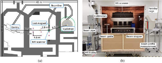
Figure 1. (a) Schematic floor plan of the proton therapy facility comprising a therapy room with rotating gantry (left) and an experimental room with a horizontal static research beam line (middle). The  G (
G ( ) lines of the cyclotron, MR scanner and the last beam line magnet are indicated by green circles. The measurement locations of the Hall probe and fluxgate magnetometers are marked by purple and orange crossmarks, respectively. (b) Experimental setup with horizontal static beam line and in-beam MR scanner (front panel of Faraday cage removed).
Download figure:
Standard image High-resolution imageThe beam travelled to the experimental room through a beam line, comprising a horizontal vacuum pipe, a series of magnets that can both deflect (dipole magnets,  ) and shape (quadrupole magnets,
  ) the beam, an energy selection system to modulate the beam energy between 70 and
  , and a beam exit window at the end of the line. The magnetic field of the beam line is dynamic, as the beam line magnets are only energised when the beam is transported into the room, and depends on the beam energy. The distance between the beam exit window and the closest upstream quadrupole magnets was
  , while the closest dipole magnet was at
  . The beam isocentre was
  downstream of the beam exit,
  downstream of the last beam line magnet,
  away from the cyclotron, and
  away from the gantry (see figure 1(a)).
After passing through the beam exit window, the beam was collimated by two cylindrical brass collimators of  thickness each having a circular shaped aperture of
  diameter to reduce primary radiation exposure of the in-beam MR scanner. In the neighbouring treatment room, a beam line mounted on a 360 degree rotatable isocentric gantry with a ferromagnetic mass of about
  was present. The earth magnetic field at the facility was about 50 μT (National Centers for Environmental Information 2018).
2.2. MR scanner
An open low-field MR scanner was chosen for this study because, as compared to high-field MR scanners, it provides larger flexibility to transport the beam to the field-of-view (FOV) and position study objects and dosimetry equipment in the FOV, smaller susceptibility artifacts, a lower specific absorption rate (SAR) allowing for real-time imaging and tumour tracking without flip angle restrictions, and lower costs (Hayashi et al 2004, Simonetti and Ahmed 2017). Although the signal-to-noise ratio of low-field scanners is lower than in high-field scanners, it is expected to be sufficient for anatomical imaging and organ motion tracking in radiation therapy (Fallone et al 2009). Furthermore, on-board low-field MR imaging has been shown to outperform on-board computed tomography imaging in MRiXT regarding organ visibility (Noel et al 2015).
The MR scanner comprised a C-shaped permanent magnet and was designed for musculoskeletal imaging (MrJ2200, Paramed Medical Systems, Genova, Italy). It generated three different types of electromagnetic fields: a vertically upwards oriented static magnetic field ( ), three pulse sequence-dependent, dynamic gradient fields for spatial encoding (typical gradient amplitude
  ) and a pulsed RF wave for 1H spin excitation at the Larmor resonance frequency (
 ) (Paramed S.r.l 2010). The scanner was equipped with a set of six receive coils dedicated to different body regions (hand, knee, shoulder, hip, upper and lower spine). The B0 field of the MR scanner had a known magnetic fringe field of
  at
at  from its magnetic isocentre (Paramed S.r.l 2010).
The MR scanner was elevated to the level of the beam line ( above floor level) using a trolley and initially placed such that its magnetic isocentre coincided with the beam isocentre.
2.3. Electromagnetic interference
2.3.1. Effects of the PT system on the MR image
A spatial or temporal change in B0 results in a Larmor frequency shift that can translate into an off-resonance voxel shift in the frequency and slice encoding directions of the MR image. For the used scanner, a difference in the B0 field of 0.5  can induce a voxel displacement of
  , depending on the pulse sequence-dependent amplitude Gx,y,z of the dynamic gradient fields. A spatially uniform perturbation of B0 can cause a uniform image shift, whereas a non-uniform perturbation can lead to local image deformations, which are harder to correct for than a global image shift.
In contrast to the pulsed RF system of a linear accelerator, the RF of the PT system is of a continuous nature and the beam, when turned on, is continuous. An RF signal external to the MRI with a frequency interfering with  can thus appear as line or zipper artefact on an MR image.
2.3.2. Spatial homogeneity of B0
The static magnetic field of the PT facility, which is governed by the fringe field of the cyclotron, may limit the achievable spatial homogeneity of B0. Therefore, a magnetic survey was conducted prior to installation of the MR scanner in the experimental room using a three-axis magnetometer (Mag585, Bartington Instruments, Oxon, UK) placed on a rectangular grid with a lattice spacing between  and
and  starting at the beam exit (see figure 1(a)). The distance of the closest grid points to the beam isocentre were
  and
and  . The measured gradient at the beam isocentre was below 1 μT m−1 and therefore considered negligible in comparison to the amplitude of the dynamic gradient fields of the MR scanner. From this, it was expected that sufficient homogeneity of the B0 field could be achieved through passive shimming.
After installation, the magnet was mechanically shimmed to generate a homogeneous B0 field. For this purpose, the magnetic field homogeneity was mapped over a  diameter spherical volume by a 16-channel rotatable magnetic field camera placed in the centre of the FOV (MFC3045/3048, Metrolab, Geneva, Switzerland). The measured peak-to-peak homogeneity was
  ppm, which was within the operating specifications of the scanner.
2.3.3. Temporal stability of B0
The temporal stability of B0 was expected to be mainly influenced by changes in the environmental magnetic field  which depends on the status and current settings of the beam line magnets and the position of the gantry in the neighbouring treatment room.
To address the first, the magnetic survey was repeated while energising the beam line magnets for different beam energies. At the grid positions closest to the beam isocentre, the mean magnetic field increase was  μT–3 μT for
  –
– beams. For comparison, a model of the last quadrupole magnet was built in OPERA3D (Thomatronik, Rosenheim, Germany) with an accuracy of 20 μT, which corresponds to the magnetic fringe field at about 60–
 downstream of the quadrupole magnet. A quadrupole magnet was modelled, not taking into account any of the surrounding iron such as present in the reinforced concrete of the floor. The measurement falls within these simulation results, which show a fringe field of
  G (
G ( ) at approximately
  (downstream along beam direction), and a rapid decay at larger distance.
The perturbations in  due to rotation of the ferromagnetic gantry in the adjacent treatment room were measured using a sensitive fluxgate magnetometer (TFM1186, Metrolab, Geneva, Switzerland). Since
  caused
  to exceed its measurement range at the beam isocentre, the magnetometer was repositioned
  towards the gantry. During a full gantry rotation of 360 degrees,
  was less than 0.3 μT in all three components. Hence,
  at the beam isocentre was expected to be even smaller and cause no relevant off-resonance image shifts.
Therefore, no severe image deformations were expected from the gradient in  and the gantry rotation, and no magnetic shielding was applied to the MR scanner. However, the measured uniform change
  due to energising the beam line magnets to the experimental room may be large enough to cause uniform image shifts. The influence of the beam line magnets to the treatment room on
  was not assessed, as these are always switched off during irradiation in the experimental room and can therefore not interfere with in-beam MR imaging.
2.3.4. RF interference
The scanner was shielded from the RF sources of the facility, mainly  , by a compact Faraday cage made of wood and 0.12 mm copper sheets. The low-power RF attenuation of the cage was
  dB at
dB at  as measured by Holland Shielding Systems BV, Dordrecht, The Netherlands. With the cage closed, external RF interference was not expected to degrade the performance of the MR scanner. Conversely, the RF waves produced by the MR scanner were not expected to interfere with the RF of the cyclotron.
2.3.5. Effects of the MR scanner on the proton beam
A proton beam with a velocity component perpendicular to a magnetic field experiences the Lorentz force and is thereby deflected. Since both the pulsed RF wave and the dynamic gradient fields were small (up to 30 μT and 20 mT m−1, respectively) in comparison to the B0 field, only the beam deflection due to the B0 field needed to be taken into account to align the beam with the FOV of the MR scanner.
2.3.6. Beam deflection
To determine the scanner's lateral position relative to the central beam axis, the central plane of its B0 field was first mapped with a high-linearity Hall probe (HHP-VU, Arepoc s.r.o., Bratislava, Slovak Republic) from the isocentre of the magnet up to a distance of ± in steps of
  (figure 5 in supporting information (stacks.iop.org/PMB/63/23LT01/mmedia)). Thereafter, the field map was used as input for Monte Carlo simulations (Geant4 toolkit version 10.2.p02 (Agostinelli et al 2003, Allison et al 2006)) to calculate the lateral beam deflection at the beam isocentre for beam energies between 70 and
  . A mean lateral beam deflection of
  relative to the central beam axis was found, ranging between
  and
and  for
for  and
and  , respectively. Thus, the MR scanner was moved by
  from the central beam line axis in the direction of the beam deflection.
To verify that the beam was well within the FOV of the MR scanner, a  long,
long,  diameter, water-filled cylindrical phantom (ACR Small MRI Phantom, Newmatic Medical, Grand Rapids, USA) was placed centrally in the FOV with the Faraday cage removed. A radiochromic film (Gafchromic EBT3, Ashland, USA) was affixed vertically to the front face of the phantom prior to irradiating it with a
  proton beam that was fully stopped inside the phantom. The dose distribution deposited on the film confirmed that the beam was centrally incident on the phantom, with a vertical and horizontal deviation from the phantom centre of
  and
and  , respectively and a vertical and horizontal spot size (1 sigma) of 5.0 mm and 5.3 mm, respectively.
2.3.7. Beam guide and beam stopper
To transport the beam to the FOV of the MR scanner with the Faraday cage closed, a cylindrical aluminium beam guide ( length,
  diameter) was installed into the wall of the cage at the point where the beam was incident on the wall. The beam guide protruded to both sides of the wall by
  . To make sure that the beam would not exit the Faraday cage (e.g. higher proton energies and different setups), a water tank was installed at the distal end of the scanner.
3. Performance test of the in-beam MR system
3.1. Beam profile quality
To quantify the beam deflection induced by the magnetic field of the MR scanner, transverse beam profiles were acquired (without Faraday cage and beam stopper) with and without MR scanner in place for 72, 125 and  proton beams using a pixelated scintillation detector (Lynx, IBA Dosimetry, Schwarzenbruck, Germany) positioned
  downstream of the MR scanner's isocentre (i.e. at
  downstream of the beam exit window). Bivariate Gaussian functions were fitted to the beam profiles to determine the beam centre and width (i.e. standard deviation) in both horizontal (i.e. parallel to the floor level) and vertical (i.e. parallel to gravity) direction. With the MR scanner in place, the beam showed a horizontal deflection of 22, 16 and
  for 72, 125 and
  , respectively, and a vertical deflection below
  relative to the central beam axis. As expected, the horizontal beam deflection dominated over the vertical deflection.
To assess the effect of the dynamic gradient fields on the beam quality, the beam profile measurements were repeated for the most sensitive beam energy (i.e.  ) during acquisition of a T1-weighted vertical and horizontal spin echo image and a T1-weighted vertical gradient echo image (gradient amplitude
  ). Difference images were acquired between beam profiles measured with and without simultaneous imaging (i.e. gradient fields) for all three sequences, and between three repeated beam profile measurements acquired without simultaneous MR imaging. The signal-to-noise-ratio (SNR) of the difference images was determined as the ratio of the mean and the standard deviation of the pixel values in a spherical area of 10 cm diameter around the beam centre, multiplied with the Rician noise factor (0.655).
No difference was observed between the beam profiles acquired with and without image acquisition (figure 2). The beam centres and widths agreed within  for all image acquisitions relative to those acquired without simultaneous imaging. The SNR of all difference images agreed within 0.1. Beam rotation was not assessed as this was only expected to occur in configurations where the B0 field is oriented parallel to the beam (Oborn et al 2015).
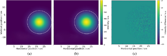
Figure 2. Transverse beam profile of a  proton beam measured after passing through the B0 field of the MR scanner (a) and measured during acquisition of a gradient echo image (b). Difference map of beam profile shows only statistical noise (c). The 10% isoline is marked in white as a point of orientation.
Download figure:
Standard image High-resolution image3.2. MR image quality
Within the scope of this study, the MR imaging performance was tested qualitatively on a knee and hand palm of a healthy volunteer and on a soft-tissue sarcoma of the right upper arm of a patient. The test consisted of pulse sequences often used for extremities: a short inversion-time inversion recovery (STIR) gradient echo image of the knee, a T1-weighted gradient echo image of the hand palm, and a T1-weighted spin echo image of the sarcoma. For these three scans, the knee, hand and knee coil was used, respectively. The scans were performed while the beam line in the experimental room was switched off.
The images showed the expected image quality for a  musculoskeletal MR scanner and enabled the discrimination of relevant anatomical structures, i.e. muscles, tendons, vessels, fat, bone, and tumour (figure 3). The observed quality of the anatomical MR images was rated to be sufficient for target volume definition and positioning by a radiation oncologist with expertise in treating extremity soft tissue sarcoma.
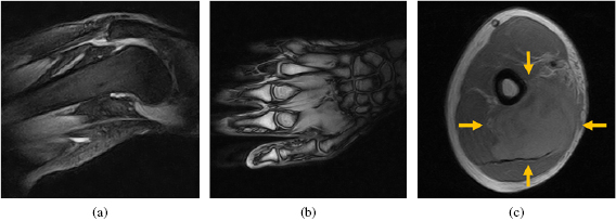
Figure 3. MR images acquired with the beam line to the MR system switched off. (a) STIR gradient echo image of a knee, (b) T1-weighted gradient echo image of a hand palm, and (c) T1-weighted spin echo image of an upper arm, with a soft-tissue sarcoma marked by arrows.
Download figure:
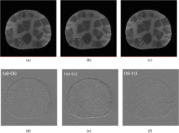
Standard image High-resolution imageTo assess the effect of the beam line magnets and the proton beam on the MR images, a mixed sausage phantom was placed in the knee coil of the MR scanner and used to acquire MR images under three scenarios: (a) without beam, (b) with energised beam line magnets and (c) during proton irradiation at  and
and  . A T1-weighted spin echo sequence was used as it represents a commonly used scan for musculoskeletal imaging (figure 4). To ensure that MR imaging in (b) was started after the current energising the beam line magnets had reached a stable level, the environmental magnetic field in the experimental room was monitored using the fluxgate magnetometer (TFM1186, see section 2.3.1.). The time delay between switching on the magnets and the magnetic field change was less than ten seconds.
Figure 4. T1-weighted spin echo image of a mixed sausage without beam (a), with energised beam line magnets (b) and during proton irradiation at  and
and  (c). Difference images ((d)–(f)) show a submillimeter uniform shift in (vertical) frequency-encoding direction.
Download figure:
Standard image High-resolution image
A submillimeter, spatially uniform shift in frequency-encoding direction was calculated from the difference images. The SNR measured in a spherical area of  diameter around the beam centre agreed within 0.1 for all three images. No additional artefacts or deformations were observed in the MR images, indicating that no severe image degradation was introduced by either the beam line magnets or the beam itself.
4. Discussion
For the first time, an open low-field MR scanner has been integrated with a static proton research beam line. The results show that beam deflection induced by the static magnetic field of the scanner needed to be taken into account for alignment of the beam and the FOV of the scanner. The pulse sequence-dependent dynamic gradient fields did not affect the beam profile. No magnetic field compensation system was required for simultaneous operation of the MR scanner and the proton therapy system, mainly because the magnetic fringe fields of both systems were low due to the large distances between them. No beam-induced MR image deformation was observed. A submillimeter and spatially uniform image shift in frequency-encoding direction was detected. Possible reasons for this shift include an off-resonance frequency shift induced by the fringe field of the beam line magnets, and uncertainties in the pre-scan RF calibration of the MR scanner, since a change in frequency affects the image in frequency encoding (i.e. readout) direction and not along phase encoding direction. This is subject to further study using different proton beam energies and pulse sequences.
The similarity between the presented in-beam MR setup and the one discussed in Fallone et al (2009) for the first MRiXT prototypes is limited to the fact that an open MR scanner has been integrated with a source of therapeutic radiation. The main differences comprise (a) a nearby clinical proton therapy cyclotron and magnetic beam line, both of which produce electromagnetic fields that could interfere with those of the MR scanner and hence degrade MR image quality, (b) a large ferromagnetic mass of the nearby rotating gantry in the therapy room, which changes the environmental magnetic field in the experimental room and could therefore perturb the magnetic field of the MR scanner, (c) relevant deflection of the primary beam due to the magnetic field (both fringe field and central field) of the MR scanner, and (d) a mobile trolley and Faraday cage including a beam guide to transport the beam through the wall of the Faraday cage without introducing RF interference and scattering of the beam.
While this study provides a qualitative proof of concept, a number of questions need to be addressed before MRiPT can be implemented clinically. First, a detailed quantification of the MR image quality including geometrical accuracy and signal-to noise ratio needs to be performed. Different pulse sequences should be included, as a gradient-dependence can be expected and  -weighted gradient echo images are known to be more sensitive to magnetic field perturbations than spin echo sequences.
Second, this setup did not comprise a beam line with a nozzle for pencil beam scanning, and the influence of the scanning magnets therein is expected to be larger than that of the beam line magnets, since the former are closer to the beam isocentre and have less steeply decreasing fringe fields. It is mandatory to address this influence in future studies. For precise dose delivery, the effect of the MR scanner's B0 field on dosimetry instrumentation, including the ionisation chambers in the nozzle, has to be quantified. Furthermore, MR pulse sequences need to be optimised in terms of contrast resolution and acquisition speed, and MR coils that are transparent to proton beams need to be designed.
The gradient amplitudes used in this work were small compared to those used in high-field whole-body MR scanners. It is expected that sequences with larger gradient amplitudes will be more robust against magnetic field perturbations induced by the proton therapy facility, as voxel displacement is inversely proportional to gradient strength.
5. Conclusion
This proof of concept shows the technical feasibility of simultaneous proton beam irradiation and in-beam MR imaging using a combination of a static proton research beam line and a low-field open MR scanner. The results justify further research and development of a first prototype for MRiPT.
Acknowledgments
This study was supported by Ion Beam Applications SA, Louvain-la-Neuve, Belgium. The authors thank Cosimo L'Abbate (Ion Beam Applications SA) for mapping the magnetic field of the MR scanner, Lorenzo Scotto (Paramed Health Services, Genova, Italy) for shimming the magnet and Stefano Gazzo (Paramed Medical Systems, Genova, Italy) for support during MR image quality optimisation. We are grateful to the healthy volunteer and the patient who underwent the MR scans.