
Abstract
The integration of 1.5 T MRI functionality with a radiotherapy linear accelerator (linac) has been pursued since 1999 by the UMC Utrecht in close collaboration with Elekta and Philips. The idea behind this integrated device is to offer unrivalled, online and real-time, soft-tissue visualization of the tumour and the surroundings for more precise radiation delivery. The proof of concept of this device was given in 2009 by demonstrating simultaneous irradiation and MR imaging on phantoms, since then the device has been further developed and commercialized by Elekta. The aim of this work is to demonstrate the clinical feasibility of online, high-precision, high-field MRI guidance of radiotherapy using the first clinical prototype MRI-Linac.
Four patients with lumbar spine bone metastases were treated with a 3 or 5 beam step-and-shoot IMRT plan. The IMRT plan was created while the patient was on the treatment table and based on the online 1.5 T MR images; pre-treatment CT was deformably registered to the online MRI to obtain Hounsfield values. Bone metastases were chosen as the first site as these tumors can be clearly visualized on MRI and the surrounding spine bone can be detected on the integrated portal imager. This way the portal images served as an independent verification of the MRI based guidance to quantify the geometric precision of radiation delivery. Dosimetric accuracy was assessed post-treatment from phantom measurements with an ionization chamber and film.
Absolute doses were found to be highly accurate, with deviations ranging from 0.0% to 1.7% in the isocenter. The geometrical, MRI based targeting as confirmed using portal images was better than 0.5 mm, ranging from 0.2 mm to 0.4 mm.
In conclusion, high precision, high-field, 1.5 T MRI guided radiotherapy is clinically feasible.
Export citation and abstract BibTeX RIS

Original content from this work may be used under the terms of the Creative Commons Attribution 3.0 licence. Any further distribution of this work must maintain attribution to the author(s) and the title of the work, journal citation and DOI.
Introduction
The challenge in radiotherapy is delivering dose to the tumour while the dose to the surrounding tissues is kept as low as possible. Image guided radiotherapy (IGRT) (Verellen et al 2007, 2008) is the key to optimize this process as it allows the localization of the tumour and organs at risk (OAR) while the patient is on the treatment table. Of all available imaging modalities for IGRT, MRI is the most versatile and suitable candidate as it provides soft-tissue contrast to enable direct tumour visualization as well as OAR localization (Lagendijk et al 2014). Moreover, it provides real-time imaging to characterize and eventually track anatomical motion (Stemkens et al 2016, Dietz et al 2017) for MRI guided radiotherapy and for dose reconstruction (Glitzner et al 2015) and ultimately real-time plan adaptation (Kontaxis et al 2017).
Integrated MRI radiotherapy systems thus promise IGRT based on excellent soft-tissue contrast. The UMC Utrecht has initiated the research on hybrid MRI radiotherapy systems (Lagendijk and Bakker 2000, Lagendijk et al 2008) by investigating the integration of a Philips 1.5 T MRI and an Elekta 6 MV linear accelerator. The proof of concept of simultaneous imaging and irradiation was given in 2009 Raaymakers et al (2009). This design has been iteratively developed to a clinical prototype by Elekta AB (Sweden), named Unity. The unique feature of this system is its 1.5 T, diagnostic image quality, MRI system (Philips Ingenia based) combined with a linear accelerator.
Various other MRI guided radiotherapy systems are being explored; the MRIdian system of Viewray (USA), which consists of a 0.35 T MRI for imaging and three Cobalt-60 sources for irradiation, in clinical use since 2014 and many MRI based IGRT procedures have been performed (Mutic and Dempsey 2014). An upgraded system with a linear accelerator instead of the Cobalt-60 sources has been brought to the clinic in 2017. The Aurora RT system from MagnetTx (Canada) consists of a 6 MV linear accelerator integrated with a 0.5 T MRI (Fallone 2014). The group in Edmonton, Canada has a non-clinical working prototype. The Australian MRI-Linac project (Keall et al 2014) aims to integrate a 1.0 T MRI and a 6MV linear accelerator, this project is currently in the technical development phase.
This study aims to demonstrate for the first time the feasibility of high-precision, high-field MRI based targeting of linear accelerator based irradiation. Focus is on the targeting accuracy, feasibility and safety of the clinical procedures.
Methods
First-in-man (FIM) treatments
Lumbar spine bone metastases were chosen for FIM because the affected vertebral body is visible on MRI and also independently on the portal imager integrated in the MRI-Linac. The portal images allow for independent, in vivo, verification of the geometric accuracy of the MRI based IGRT procedure. Vertebral bone metastases are treated with a single fraction of 8 Gy for pain relief.
An IRB approved, industry (Elekta AB, Sweden) sponsored trial aimed at treating five patients with painful lumbar spine bone metastases with the MRI-Linac. A single fraction of 8 Gy was prescribed to the target volume, defined by the entire vertebral body, with the following constraints V7.2 Gy > 90%, D98% > 6.4 Gy, D0.1CC < 8.8 Gy while the dose to the spinal cord was minimized (D0.1CC < 8.56 Gy) as was the dose to the remainder of the body (D0.1CC < 8.8 Gy).
The 1.5 T MRI-Linac system
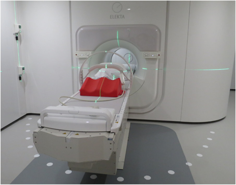
The system is a 1.5 T MRI system with a ring-based gantry containing a 7 MV standing wave linear accelerator. The radiation beam is collimated via a non-rotational 160 multi-leaf collimator (MLC) with 7.1 mm wide leaves at isocenter plane, travelling in cranial-caudal direction. Maximum field size in the isocenter is 22 cm in cranial caudal and 57 cm in lateral direction. The layout of the system has conceptually not changed since presented by Raaymakers et al (2009). The gantry ring is hidden by the Faraday cage which makes the appearance of the system more like a diagnostic scanner than a therapeutic device. Figure 1 shows a photograph of the clinical prototype MRI-Linac.

Figure 1. Photograph of the MRI-linac at the UMC Utrecht. The lasers for patient set-up, the patient positioning devices as well as the RF receive coil are shown.
Download figure:
Standard image High-resolution imageThe MRI-Linac table can move in cranial-caudal direction only, so the patient is set-up at a virtual isocenter indicated by lasers and then positioned close to the MRI-Linac isocenter. The patient set-up is not critical as in conventional radiotherapy practice since the actual tumour location is subsequently assessed using MRI and a new IMRT plan is made to accommodate for the latest tumour location and patient anatomy.
A dedicated acceptance and quality assurance (QA) and quality control (QC) procedure was developed and executed to quantify the MRI performance, linac and portal imager performance, the treatment planning, the dosimetric perfomance and the geometric performance of the MRI-Linac.
In particular the geometric fidelity was carefully assessed for FIM treatments and was found to match a regular 1.5 T Philips Ingenia MRI system (Tijssen et al 2017). The MRI distortion map is heterogeneous, the maximum distortions are 1.1 mm and located at the tips of a star-shaped pattern in a 25 cm diameter spherical volume, while in the central area distortions are below 0.5 mm and this is typically the volume to localize the lumbar spinal bone metastasis for FIM. A 4-element posterior coil is positioned under the table, fixed relative to the isocenter, both this coil and the table are accounted for in the treatment planning, i.e. Monaco (research version 5.19.02 Elekta AB, Sweden). The anterior 4-element coil is positioned floating just above the patient, it is radiation transparent but for the FIM beam configuration, no beams are entering through this coil anyway. MRI interpretation during beam-on is not affected (Tijssen et al 2017).
The linac of the MRI-Linac is commissioned according to regular guidelines like the AAPM Task group 142 report (AAPM TG 142 2009) and the NCS 9 protocol (NCS 9, 1996), but measurement execution was adapted to be compliant with the presence of the high magnetic field. The performance was then assessed for the dosimetry and geometry separately.
The treatment planning system (TPS) was commissioned using regular guidelines (NCS report 15, NCS report 22). Patient QA was performed by measuring 20 IMRT plans (ten 3-field plans and ten 5-field plans) using both GafChromic film(EBT3 film, Ashland ISP Advanced Materials, NJ, USA) and a CC04 ionisation chamber (IBA, Belgium) in a polystyrene slab phantom. The chamber readings were used to normalise the film dose distributions. An example is shown in figure 2. The mean absolute difference between the planned and measured doses in the isocenter was 0.5% of the planned dose (range −1.8% to +2.0%). The mean percentage of points meeting the gamma criterion of 3%/3 mm (Low et al 1998) was 98.8% (range 92.2%–100%).
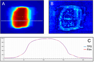
Figure 2. QA performance of the linac of the MRI-linac. 20 plans were delivered on polystyrene phantom twice, first with film, then with ionization chamber. The calculated results were compared to the measured film distributions (A) and a gamma analysis (B) of 3%/3 mm was performed. (C) Shows a profile comparison between the measured and calculated dose distribution.
Download figure:
Standard image High-resolution imageFor the geometrical performance, the Alderson RANDO phantom (Radiology Support Devices, CA, USA) was used. A plan, including radiographic projections for the first segment of each treatment field, was generated as described in 'Treatment Procedure' below. In short, the MV images recorded during plan delivery were registered to the projections generated from the planning dataset. A 3D vector was calculated by taking the average offset between images along each axis for all fields. The length of the 3D vector is defined as the geometrical accuracy (see also figure 4 for the clinical example). It was shown that the geometrical accuracy of the complete MRI-Linac procedure in phantoms is better than 0.5 mm.
Treatment procedure
The workflow is automated while critical decisions are delegated to the operator. For this purpose, an in-house developed workflow engine, the Utrecht treatment session manager (UTSM) was used. Central in UTSM is the Dicom database, in which all patient data relevant for the treatment is stored. All actions launched for the workflow are triggered by updates received by the server. This way, an action is always provided with the latest data and parallel processes, like visualization and dose calculation, can be launched. This approach ensures data integrity and straight-forward monitoring of the treatment progress. An in-house developed visualization and contouring program (VolumeTool, Bol et al 2009) is permanently running and offering views and contour editing possibilities on all the data of the patient as these become available during the treatment: the deformed CT, online MRI, contours, dose distributions, gamma distributions between Monaco and OnCentra dose calculations, and dose volume histograms. The procedure can be divided in a set of pre-treatment activities and a set of online activities.
The pre-treatment actions are:
- 1.Pre-treatment CT (Brilliance CT big bore, Philips, The Netherlands) and 1.5 T MRI (Ingenia, Philips, The Netherlands) images are acquired for target definition and Hounsfield values.
- 2.Two IMRT plans are generated. The IMRT plan for the MRI linac, including the presence of the 1.5 T transverse magnetic field, is generated using a research version of Monaco (v5.19.02). A second plan for a conventional linac using Monaco (v5.11.01, Elekta AB, Sweden) was generated as back-up plan in case it would not be possible to proceed with treatment on the MRI linac.
- 3.Quality assurance tests were performed on the MRI linac plan as discussed above. Also, an independent recalculation of this plan was performed via OnCentra (Elekta AB, Sweden), which is based on a Collapsed Cone algorithm, and cannot directly simulate the effect of the magnetic field. This recalculation serves as an independent, 3D dose check of the Monaco dose distribution. Hackett et al (2016) showed that this procedure is suitable for voxel-to-voxel comparisons in the target volume for a variety of treatment sites. A gamma-comparison between the OnCentra and Monaco dose distributions was performed, using a 3%/3 mm criterion. Note that this IMRT plan will not be used in the on-line setting, this is merely a QA check on the procedure.
For the actual MRI-Linac treatment, schematically illustrated in figure 3, a brief description of the steps is:
- 1.The patient is positioned on the MRI-Linac and an online MRI (3D SPGR) is acquired and presented to the operators.
- 2.The contours and the Hounsfield values are acquired by registration of the pre-treatment data with the online MRI using the deformable registration software ADMIRE (Version 1.13.3) from Elekta. The results are visualized and manually checked and the contours are edited if deemed necessary by the radiation oncologists.
- 3.Based on this data set an IMRT plan is generated in Monaco v5.19.02, this takes approximately 5 min which was considered acceptable for the FIM online planning. This plan is presented using Volumetool and manually reviewed by the radiation oncologists and medical physicists. In parallel, for online QA, the plan is recalculated using OnCentra as also described in step 3 of the pre-treatment activity.
- 4.To check the patient stability after the contour and planning steps a MRI scan (3D SPGR) is repeated and the contours are overlaid on this data and visually checked for alignment before the radiation oncologist approves proceeding.
- 5.Treatment delivery starts and the MV panel is activated to capture all portal images for the off-line validation of the MRI based treatment guidance. Also, during irradiation a seven second MRI (3D balanced SSFP) is acquired and presented every seven seconds for continuous patient monitoring. The intra-beam MRI is acquired as a feasibility and the data is monitored by the operators. There are no direct treatment consequences associated to the intra-fraction MRI, it merely serves as a redundant patient monitoring next to a conventional camera system. Also, the data are used after the treatment for proof of concept of time-resolved dose reconstruction, much like presented by Glitzner et al (2015) (this is beyond the scope of this paper).
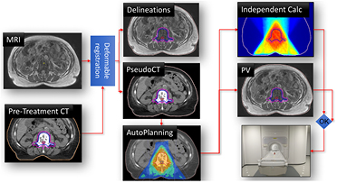
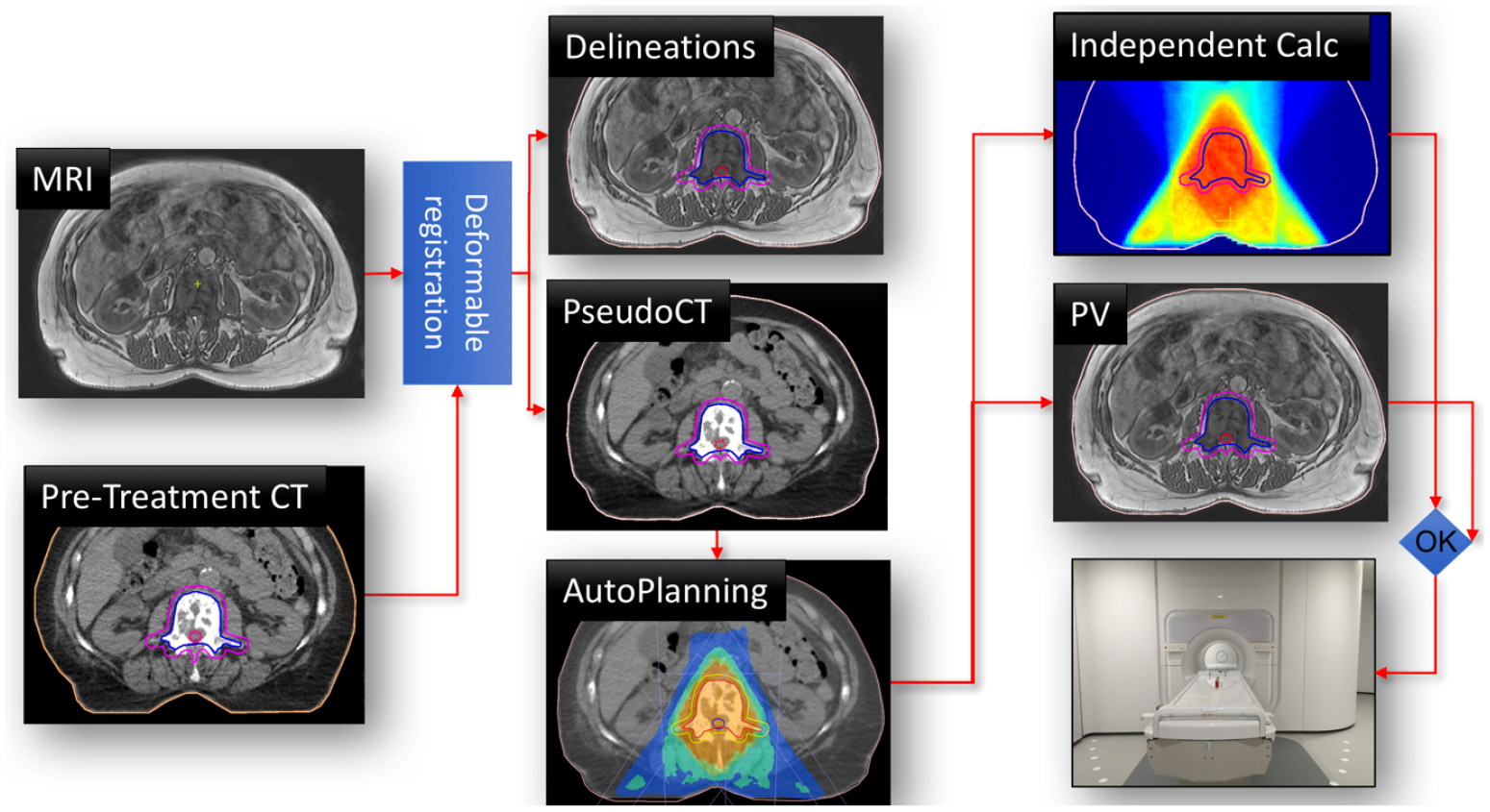
Figure 3. Online workflow of the MRI-linac treatment. The online MRI is registered to the pre-treatment CT to generate a warped CT and to propagate the pre-treatment contours. An IMRT plan is generated automatically and is validated via independent dose calculations and after position verification (PV) by an additional MRI, beam delivery is started at the MRI-linac.
Download figure:
Standard image High-resolution imageEvaluation of the treatment accuracy
To assess the targeting accuracy of the MRI guidance, the MV projection images of the first segment of each field were registered to the calculated projection images from the warped CT using Theraview (Version 5.2.6, Cablon Medical, The Netherlands). The geometric accuracy was determined as described for the geometrical performance test. The calculated projections are based on the online MRI in which the Hounsfield values from the pre-treatment CT were assigned after the image registration. If the MRI targeting is correct and the intra-fraction motion is small, the calculated projection and the measured projections should coincide.
The dosimetric accuracy of the plan used for treatment was validated post-treatment, as described in step 3 of the pre-treatment activities.
Results
Patients and clinical procedures
Five patients were included, from mid-May to mid-July 2017 (with current follow-up range of 2–8 weeks), after they gave written informed consent. Four of the patients were treated on the MRI-Linac as intended. Patient 1, 65 years, target lumbar vertebra 4 (L4), patient 2, 74 years, L4, patient 3, 61 years, L2–L3, patient 4, 70 years, L1. No unexpected adverse events have been reported so far. Although not a study endpoint, palliative effect was achieved in all treated patients, with two of them having a temporary pain flare. The fifth patient, after having signed informed consent, experienced severe disease progression with neurological impairment the day after signing and was therefore no longer eligible for treatment within FIM. This rapid progression was diagnosed during the pre-treatment MRI workup and required emergency intervention.
Dosimetric accuracy
For each of the 4 (MRI-Linac treated) FIM patients the same QA procedures were performed for both the pre-treatment plan and the plan delivered on the MR-linac as discussed in step 3 of the pre-treatment activities. The mean difference was 0.4% of the calculated dose (standard deviation 0.8%, maximum difference 1.7%). The average percentage of points satisfying the gamma criterion of 3%/3 mm was 97.7% (standard deviation 2.0%, minimum pass rate 93.7%).
Geometrical accuracy
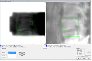
The accuracy of in vivo delivery was validated by comparing the portal images of the IMRT segments to the MRI based, calculated projections, as shown in figure 4. This was done for the first segment of each beam and close alignment was found between them, on average 0.3 mm with a range of 0.2 to 0.4 mm.
Figure 4. The measured MV portal image (on the left) and calculated projection image based on the warped CT (on the right). The MV images are registered on the calculated projections and thus the contours can be overlaid on both images for visual inspection. The quantitative metric is taken by the directional shift found from the registration.
Download figure:
Standard image High-resolution image
Timing
The individual MRI-Linac procedures were very reproducible, on average taking 41 min (range 33–44 min) and were well tolerated by the patients. This excludes approximately 15 min of bringing the patient into the treatment room and set-up on the table. The time to beam-on (i.e. time for imaging, contour definition and online treatment planning) was on average 25 min (ranging from 20–28 min).
Patient stability
Patient stability was monitored during irradiation by acquiring a 3D balanced SSFP every 7 s. Some minor position shifts of surrounding structures were seen, but no movements of the target volume.
Discussion and conclusion
The aim of this work is to demonstrate that high-field, 1.5 T MRI guidance is clinically feasible for high-precision targeting of radiotherapy. In this first clinical study spinal vertebral bodies, i.e. bony structures, were targeted because this allowed independent validation of targeting accuracy by using portal images and clinical gain was not intended. For these bone metastases, high-precision targeting is also clinically feasible with conventional cone-beam CT (cbCT) linacs (e.g. Guckenberger et al (2014)). Yet, MRI guidance provides targeting to arbitrary tumour sites due to the unrivalled soft-tissue contrast. Moreover, MRI can provide real-time feed-back, providing input for intra-treatment adaptations. This versatility of MRI opens many options for improving radiotherapy treatments (Lagendijk et al 2008, 2014). Now the concept of MRI-Linac has successfully been proven in the first clinical setting and reveals an outstanding level of dosimetric and geometric accuracy of the radiation beam we will work towards real-time adaptive MRI guided radiotherapy using the MRI-Linac, for instance following the approach of Kontaxis et al (2017).
In summary, the combination of diagnostic quality MRI information of a patient on the treatment table and online planning facility allows making treatment decisions directly before and during radiation delivery. Furthermore, the whole procedure can be completed within a clinically acceptable timeframe. This helps to better guide the treatment to the actual anatomical situations. The MRI-Linac shows a stereotactic quality dose delivery.
Acknowledgment
The authors wish to thank the Dutch Cancer Society for their financial support (Grant 2015-0848).