

Abstract
We developed new teaching materials, electrical resistors and capacitors, using carbon nanotube (CNT) paper and carbon fibre (CF) paper to foster students' creative thinking, thereby deepening and extending learning. Using a CNT-paper electrical resistor, it is possible to elucidate the dependence of the resistance value on the length and width. The resistance value is proportional to the length and inversely proportional to the width of the paper. In the case of the CF-paper capacitor, it is also possible to clarify the dependence of the capacitance value on the area and the distance between papers. The capacitance value is proportional to the areas of the papers and inversely proportional to the distance between them. Based on the results of our experiments using the new teaching materials, we confirmed that the measured values were in good agreement with the values predicted by theoretical calculations. Using these materials, it becomes possible for students to visually and actively learn about electrical resistance and capacitance through experiments by themselves and in discussion with other students, in contrast to the traditional teaching methods practiced in many schools worldwide. We found that teaching methods using these materials are a useful and easy way to teach the basic concepts of resistance and capacitance with geometric factors in classrooms.
Export citation and abstract BibTeX RIS
1. Introduction
The development of effective teaching materials for electric circuits is an important theme and area of active research in physics education. The most important points of this theme are to be able to easily construct easily simple circuits (for an example, see [1]) and to visually understand electric current. Because electric current is invisible, it is quite difficult to imagine and understand the concepts. Electrical resistors made using pencil [2–4] and capacitors made using aluminium foil [5, 6] are famous teaching materials for understanding the concepts of resistance and capacitance visually. Some metals are often used as capacitor plates, but sometimes a piece of paper drawn on using graphite is used because it is easy to construct [7, 8]. These materials are easy to handle and help many students to understand visually.
However, papers drawn on using graphite are not easy to experiment with quantitatively, nor are they reproducible. We focused on the development of teaching materials for electric resistors and capacitors using carbon nanotube (CNT) paper and carbon fibre (CF) paper. These papers are suitable quantitative and reproducible experimental teaching materials.
The resistance values of CNT papers are lower than other carbon-impregnated conductive papers which are used for plotting equipotential curves [9]. Every student and teacher can incorporate CNT papers into a circuit and turn on a LED lamp. The resistance values of CF papers are lower than those of CNT papers.
We obtained CNT paper and CF paper from TT Trading in Japan [10]. The CNT paper cost 500JPY (4USD, 3GBP) and the CF paper cost 250JPY (2USD, 1.5GBP) per A4 sheet. The experiments are cost-effective and easy to run in a low-budget school. The prices are inexpensive, compared to a standard rheostat. The surface resistivity of the CNT paper is 100 Ω and that of the CF paper is 30 Ω as supplied by the manufacturer. The surface resistivity is the resistance of the unit area, i.e. a square 1.0 cm in length and width. The unit of surface resistivity is ohms per square ( sq−1) or just
  .
.
Experimental methodologies and data for these themes are not found in any textbooks for secondary school physics (for example [11]). Using our new teaching materials, every student and teacher can do experiments in the classroom quantitatively and reproducibly. These paper-based circuit elements are easy to handle and useful for creative thinking to deepen and extend learning.
In this article, we focus on electrical resistors using CNT paper in section 2. In section 3, we focus on capacitors using CF papers. In section 4, we discuss experimental results obtained using the newly developed educational materials. Finally, in section 5, we offer some conclusions.
2. Electrical resistor using CNT paper
The electrical resistance R is generally given by
Here,  is electrical resistivity,
  is the length of the resistor and
  is the cross-sectional area of the resistor. The electrical resistance value is proportional to the length and inversely proportional to the cross-sectional area.
A schematic model of a piece of CNT paper is shown in figure 1. If we apply a voltage between the right side and the left side, the cross-sectional area of the CNT paper is  . Therefore, the resistance of this CNT paper is given by

Figure 1. A schematic model of a piece of CNT paper.
Download figure:
Standard image High-resolution imageHere,  is the surface resistivity;
  . In CNT-paper electrical resistors, the resistance value is proportional to the length and inversely proportional to the width.
We used CNT papers as electrical resistors because, with CNT paper, it is easy to visually understand the dependence on the shape. A typical CNT paper resistor is shown in figure 2. It is made of a plastic ruler, two stainless steel pinchcocks and an appropriately sized piece of CNT paper.
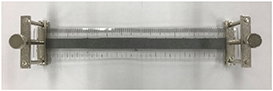
Figure 2. A typical CNT paper resistor.
Download figure:
Standard image High-resolution imageUsing the CNT paper electrical resistor, it is possible to clarify the dependence of the resistance value on the length and width and we can easily understand this concept visually. For example, we can focus on the proportional relationship between the resistance value and the length. In figure 3, we show experimental results obtained using a current checker for different lengths between electrodes of 3.0 cm (on the left) and 19.0 cm (on the right), respectively. In both cases, the width of the resistor is 2.0 cm. We found that the left LED is brighter than the right LED because the left resistance value becomes smaller than that on the right with reducing length, as shown in equation (2).
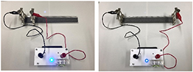
Figure 3. The brightness of LEDs versus the lengths of the CNT papers.
Download figure:
Standard image High-resolution imageWe made measurements of the resistance values of CNT papers with four different widths (0.5 cm, 0.75 cm, 1.0 cm and 2.0 cm) using a conventional digital multimeter (Keysight, U1242B). The value of the resistance is proportional to the length of the paper, as shown in figure 4. We can also easily obtain the surface resistivity by estimating the slope of each line in figure 4. In the case of these CNT papers, we obtain a value of 130 Ω for the surface resistivity by experiment.
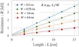
Figure 4. Resistance values as a function of length for the CNT papers. The widths of the papers are 0.5 cm, 0.75 cm, 1.0 cm and 2.0 cm.
Download figure:
Standard image High-resolution imageWe also made measurements of the resistance value of the above CNT papers at two fixed lengths, 10.0 cm and 20.0 cm. The resistance values are inversely proportional to the width in each case, as shown in figure 5. We re-plotted the conductance G as a function of width for the papers in figure 6. Here the conductance, G, is defined as the reciprocal of the resistance. Its relationship to resistance is expressed as
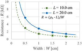
Figure 5. Resistance values as a function of width for the CNT papers. The lengths of the papers is 10.0 cm and 20.0 cm.
Download figure:
Standard image High-resolution image
Figure 6. Conductance (the reciprocal of resistance) values as a function of width for the CNT papers. The lengths of the papers were 10.0 cm and 20.0 cm.
Download figure:
Standard image High-resolution imageA linear fit was obtained that depended on the reciprocal of the resistance value and the width. Based on the results of these experiments using CNT papers as electrical resistors, we confirmed that the measured values were in good agreement with the values predicted by theoretical calculations.
Here, we propose a new way to teach combined resistance using our new teaching materials. It is well known that the formula for the combined resistance value of two resistors (R1 and R2) is expressed as,

for a series connection and
for a parallel connection, respectively.
The combined resistor made of two CNT paper resistors, each with a length L for the series connection and a CNT paper resistor with a total length of 2L, the sum of two CNT paper resistors are shown in figure 7. We made measurements of the resistance values of the combined resistor for a series connection and a resistor having the same total length using a conventional digital multimeter. The values obtained for these measurements are shown in table 1. R1 and R2 have the same length, but these resistance values do not match, due to slight differences in width depending on the creation process in table 1. One paper resistance value is lower than the combined resistance because of the contact resistance between R1 and R2. We confirmed that the combined resistance value was in good agreement with the resistance of one CNT paper with the same total length.

Figure 7. The upper CNT paper resistor is a combined resistor made from two CNT paper resistors each with a length L in series. The lower CNT paper resistor has a total length of 2L, the sum of the lengths of the two papers. The combined (upper) resistance value is equal to the lower resistance due to the total length.
Download figure:
Standard image High-resolution imageTable 1. The combined resistance value of two CNT paper (length L) resistors in series and one CNT paper resistance value with a total length of 2L.
| W = 1.0 cm | Length (cm) | Resistance (kΩ) |
|---|---|---|
| Paper R1 | 6.0 | 0.80 |
| Paper R2 | 6.0 | 0.84 |
| Combined resistance | 6.0 + 6.0 | 1.64 |
| One paper | 12.0 | 1.57 |
The combined resistance of the two CNT paper resistors, each with a width of W, in parallel, and a CNT paper resistor with a total width of 2W (the sum of the two CNT-paper resistors) are shown in figure 8. We also made measurements of the combined resistance value for the parallel connection and a resistor having the width of 2W in the same way. The values obtained with these measurements are shown in table 2. R1 and R2 have the same widths, but their resistance values do not match due to slight differences in length depending on the creation process in table 2. We also confirmed that the combined resistance value was in good agreement with that of one CNT paper with the same total width of 2W.

Figure 8. The upper CNT paper resistor has the combined resistance of two CNT paper resistors of width W in parallel. The lower CNT paper resistor has a total width of 2W, i.e., the sum of the two widths.
Download figure:
Standard image High-resolution imageTable 2. The combined resistance and conductance values of two CNT-paper (width W) resistors in parallel and one CNT-paper's resistance and conductance values (total width 2W).
| L = 6.0 cm | Width (cm) | Resistance (kΩ) | Conductance (mS = kΩ−1) |
|---|---|---|---|
| Paper R1 | 1.0 | 0.82 | 1.22 |
| Paper R2 | 1.0 | 0.86 | 1.16 |
| Combined resistance | 1.0 + 1.0 | 0.43 | 2.32 |
| One paper | 2.0 | 0.43 | 2.32 |
Based on these experimental results, we can propose a new way of teaching combined resistance. Students need to predict the combined resistance values of the CNT papers before making measurements. During deep thinking, some will find the rule for combined resistance.
The values are equal to the resistance values for a resistor of the same total length (for a series connection) and the same total width (for a parallel connection). In other words, in the case of serial connection, the total resistance value is equal to the sum of the values of the papers used. For the parallel connection case, the total conductance value is equal to that of the sum the values of the papers. Students will naturally understand the meaning of the formulas for combined resistance, equations (4) and (5). This method of teaching based on the use of CNT paper resistors should be a useful and easy way to teach the concepts of combined resistance with geometric factors in classrooms.
3. Capacitor using CF paper
The capacitance of a parallel-plate capacitor C is generally given by
Here,  is permittivity,
  is the area of the plate and
  is the distance between the two plates. The capacitance is proportional to the area of the plate and inversely proportional to the distance between two plates.
We made a new parallel-plate capacitor using CF paper. The resistance values of CF papers are lower than those of CNT papers for the same shape. The surface resistivity value of a typical CF paper is 30  . With CF paper (figure 9 left), it is easier to construct a capacitor than with some metals. We can make capacitors with arbitrary plate areas by cutting the CF papers.

Figure 9. A piece of CF paper (left) and other parts (right).
Download figure:
Standard image High-resolution imageA schematic model of a capacitor made using CF paper is shown in figure 10. The plates are made of a piece of CF paper and copper. The area of the plate is equal to the area of the piece of CF paper, because the cut CF paper is narrower than the copper. The distance between plates is determined by a piece of paper. We put some acrylic board and stainless steel weights on a piece of CF paper to fix it (figure 9 right). The acrylic board has a hole in it, to conduct electricity to the piece of CF paper. The weights have the role of reducing the gap between papers. We have confirmed that the larger the mass of the weights, the smaller the distance between plates. When the mass increases, the capacitance also increases, but it converges to a certain value. In this experiment, to arrange the weights evenly on the CF paper and to use consistent conditions, four cylindrical weights each with a diameter of 5.0 cm are arranged at the four corners of the CF papers. The mass of each weight is 280 g.
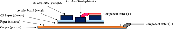
Figure 10. A schematic model of a capacitor made using CF paper.
Download figure:
Standard image High-resolution imageWe made measurements of the capacitance values of our new capacitors using a component tester (RS Pro, 1 233 221). Figure 11 shows the experimental system for the case of  (
( ). The capacitance value is proportional to the area of the CF papers, as shown in figure 12.
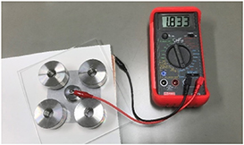
Figure 11. The experimental system of the capacitor using CF paper for the case of  (
( ).
).
Download figure:
Standard image High-resolution image
Figure 12. The capacitance value versus the area of the plate. The areas of the plates are 20 cm2, 40 cm2, 60 cm2, 80 cm2 and 100 cm2.
Download figure:
Standard image High-resolution imageWe also made measurements of the capacitance value using ten different distances between two plates with areas of 50 cm2, and 100 cm2. The capacitance values of each paper were inversely proportional to the distance between the plates, as shown in figure 13. The distance was adjusted by varying the number of papers. We re-plotted the capacitance as a function of the inverse of the distance of plates in figure 14. A linear fit was obtained that depended on the reciprocal of the capacitance value and the distance. The intercept is a positive value because there is some thickness of air between a piece of CF paper and the copper. We expect a similar result with a thicker paper separator, but the slope of each line in figure 14 will be large.

Figure 13. The capacitance versus the distance between two plates. The areas of the plates are 50 cm2 and 100 cm2.
Download figure:
Standard image High-resolution image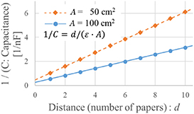
Figure 14. A reciprocal plot of capacitance versus the distance between the two plates. The areas of the plates are 50 cm2 and 100 cm2.
Download figure:
Standard image High-resolution imageWe propose a new way to teach about combined capacitors using CF paper capacitors. It is well known that the combined capacitance values of some capacitors (C1, C2, ... ) are formulaicallyexpressed as

for a parallel connection and
for a series connection, respectively.
Figure 15 shows the experimental system of the combined capacitor using CF papers for the case of the parallel connection of two capacitors. We used four stainless steel weights. The lower plate is copper, and the upper two plates are CF paper.
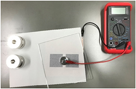
Figure 15. The combined capacitance using CF papers infor the case of two capacitors connected in parallel.
Download figure:
Standard image High-resolution imageThe combined capacitance value for a parallel connection is obtained as the sum of the individual capacitances. Because the combined capacitor has the total plate area, it is the sum of all the plate areas.
We made measurements of the combined capacitance values of one to four CF-paper capacitors in parallel. As we can see from figure 16, the combined capacitance value is proportional to the number of capacitors. The calculated values using the capacitance of the first capacitor (C1) are shown by a dashed line in figure 16.
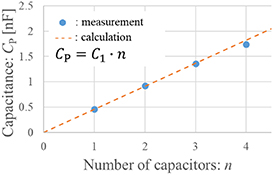
Figure 16. The measured results for the combined capacitance of a parallel connection versus the number of capacitors.
Download figure:
Standard image High-resolution imageThe combined capacitance of two capacitors using CF papers with the same areas in series is shown in figure 17. We made measurements of the combined capacitance values of one to four CF-paper capacitors in series. The combined capacitance value was inversely proportional to the number of capacitors, as we can see in figures 18 and 19. The calculated values using the capacitance of the first capacitor (C1) are shown by a dashed line. Based on the results of our experiments using CF paper, we confirmed that the measured values were in good agreement with the expected value predicted by theoretical calculations.

Figure 17. The combined capacitance of two capacitors using CF papers with the same areas in series.
Download figure:
Standard image High-resolution image
Figure 18. The results of measuring the combined capacitance values for a series connection.
Download figure:
Standard image High-resolution image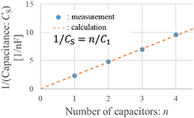
Figure 19. A reciprocal plot of the combined capacitance values for a series connection.
Download figure:
Standard image High-resolution image
We propose the following new way of teaching combined capacitance. After making a prediction, students can make measurements of the combined capacitance values for themselves. By deep thinking, some will find the rules for combined capacitance. The combined capacitance values are equal to the capacitance value of the total area (for a parallel connection) and the sum of the reciprocals of the individual capacitances (for a series connection). Therefore, the combined capacitance value is equal to the sum of all the papers' capacitance values for the parallel connection case. For the series connection case, the combined capacitance value is equal to that of the sum of the reciprocals of the individual capacitances' or a similar expression. Students will also understand the meaning of formulas for combined capacitance, equations (7) and (8). This way of teaching with CF paper capacitors should be a useful and easy way to teach the concepts of combined capacitance with geometric factors in classrooms.
4. Discussion
By using CNT paper electrical resistors, we can visually understand the resistance value based on the brightness of LEDs. It is possible to clarify the dependence of the resistance value on the length and width. In particular, the resistance value is proportional to the length and inversely proportional to the width. It also becomes possible for students to learn about electrical resistance visually and actively through experiments by themselves and in discussion with other students, rather than through the traditional teaching methods practiced in many schools worldwide.
We can explain two advantages of using this experiment instead of others in the textbooks. The first is that it is possible to visually understand resistance using the brightness of LEDs, because the surface resistivity of CNT paper is about 100 Ω. The other is that some papers are easy to cut. For example, there is a possible activity of hand-making resistors with arbitrary resistance values as part of inquiry-based learning. We expect that even resistors of the same values will come in a variety of shapes, depending on the creativity of the students. This helps to foster students' creative thinking.
In the process of learning about combined resistance, the concept of combined resistance can be understood visually and experimentally. The combined resistance of a series connection can be understood as the sum of the lengths of the resistors. The combined resistance for a parallel connection can be understood as the sum of the widths of the resistors.
In the case of CF-paper capacitors, it is also possible to clarify the dependence of the capacitance value on the area and the distance between plates. In particular, the capacitance value is proportional to the area of a plate and inversely proportional to the distance between the plates. By using these capacitors, it also becomes possible for students to learn about capacitance visually and actively through experiments and discussion with other students. The main advantage of using this experiment instead of others known in the textbook is that it is easy to construct paper capacitors, compared to some metals (for example, copper/aluminum plates). For instance, students can make CF-paper capacitors with arbitrary capacitance values using creative thinking.
In the learning of combined capacitance, we can teach visually and experimentally. The combined capacitance of a parallel connection can be understood as the sum of the areas of the plates. The combined capacitance for a series connection can be understood as the sum of the reciprocals of the individual capacitances. This means that a visual understanding of combined capacitance is possible.
The electrical resistors and capacitors made using carbon-based papers are easy to handle and understand visually. Moreover, it becomes possible for students to experiment in a quantitative and reproducible way in the classroom.
5. Conclusions
We developed new teaching materials to help in the visual understanding of electric current. The CNT paper electrical resistor is easy to handle and is it easy to understand the dependence of the resistance on the length and the width. The CF paper capacitor is also easy to handle and it is easy to understand the dependence of the capacitance value on the area and the distance between plates. We found that teaching methods using the resistor and the capacitor with carbon-based papers should be a useful and easy way to teach the basic concepts of electrical resistance and capacitance with geometric factors in classrooms. Our new teaching materials help to foster students' creative thinking, thereby deepening and extending learning. We expect our new teaching materials to be used in many lower and upper secondary schools' science and physics educations worldwide.
Biographies

Michiya Shintsuruta is a PhD student at Graduate School of Education, Aichi University of Education, Japan, where obtained his M.Ed. in Physics Education. He was a secondary school science teacher for five years. He has also taught science at an elementary school for three years. His research topic is the development of effective physics education methods using new teaching materials.

Hirokazu Okubo is a PhD student at Graduate School of Education, Aichi University of Education, Japan. He had been a high school teacher for thirty-six years. After retirement, He obtained his M.Ed. in Physics Education at Chubu University. He is researching the development of physics teaching materials that can be used in inquiry learning.

Tsutomu Iwayama is a Professor of Physics and Vice-President, Aichi University of Education, Japan. He obtained his BSc at Waseda University and PhD degree at Nagoya University, Japan. He was also a Research Fellow at University of Sussex and University College London, UK. He has contributed significantly to research at the international level and published papers mainly in the field of nanostructured materials.