

Abstract
As the need for the manufacturing of complex surface topographies increases, traceable measurement with known uncertainties can allow a manufacturing process to remain stable. Material measures are the link in the chain that connects the surface topography measurement instrument's output to the definition of the metre. In this review, the use of material measures is examined for the purposes of instrument calibration and performance verification based on the metrological characteristics framework, as introduced in ISO 25178 part 600. The material measures associated with each metrological characteristic are investigated in terms of fabrication, geometry and functionality. Material measures for metrological characteristics are discussed in a sequential approach, focusing on material measures that have been developed for specific measurement technologies and optical surface topography measurement instruments. There remains a gap in the metrological characteristic framework for the characteristic, topography fidelity, and the review highlights current methods using reference metrology and alternative approaches using virtual instruments to quantify the effects of topography fidelity. The influence of primary instruments is also reviewed in the context of uncertainty propagation. In the conclusion, the current challenges are identified with regards to the scarcity of available material measures in the lower nanometre range, and the limitations in terms of cost, complexity, manufacturing time and industrial applicability.
Export citation and abstract BibTeX RIS

Original content from this work may be used under the terms of the Creative Commons Attribution 4.0 license. Any further distribution of this work must maintain attribution to the author(s) and the title of the work, journal citation and DOI.
1. Introduction
Traceability is an integral part of any manufacturing process as it ensures the accuracy and consistency of measurements for a product or assembly [1]. The International Vocabulary of Metrology (VIM) defines traceability as the 'property of a measurement result whereby the result can be related to a reference through a documented unbroken chain of calibrations, each contributing to the measurement uncertainty' [2]. In this paper, we will be considering the traceability of the measurements of surface topography, focussing on material measures. A measurement result can be affected by a variety of influence factors which can be dependent on the surface measuring instrument used (influence factors for specific instruments can be found in the ISO 25178 parts 60X series, see [3–9]). Measurement uncertainty is a term used to characterise the effect of influence factors and is expressed as 'the dispersion of the quantity values being attributed to a measurand' [2]. Knowledge of the uncertainty for a measurement provides insight into whether the process is under control. Also, given the difficulty of modelling the interaction between an optical instrument and a surface, the calibration of optical instruments a complex task [10]. The calibration framework in ISO 25178 part 600 [11] introduces several metrological characteristics (which include measurement noise, flatness deviation, amplification, linearity and squareness of the axes, topographic spatial resolution, and topography fidelity) that aim to capture all the factors influencing a measurement result. Once determined, the metrological characteristics can be propagated through an appropriate measurement model allowing for the evaluation of measurement uncertainty [12].
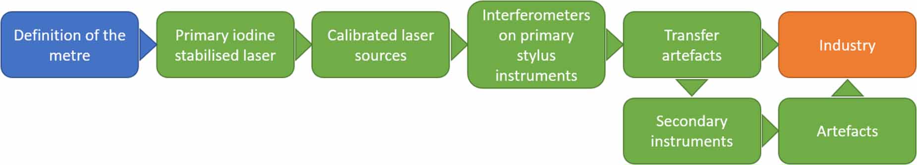
Material measures are physical measurement artefacts used for the determination of the metrological characteristics [13]. As part of the traceability infrastructure illustrated in figure 1, material measures are calibrated using primary instruments, often stylus based [14]. Prior to the emergence of areal surface measuring instruments, the calibration of profile measuring instruments was covered in ISO 5436 parts 1 and 2 and in ISO 12179 [15–17]. In detail, ISO 5436 part 1 describes the five different types of material measures used for the calibration of stylus instruments in profile mode while ISO 5436 part 2 details the measurement artefacts used for the verification of the software of measuring instruments. Finally, ISO 12179 presents the methodologies for calibrating a profile measuring instrument.
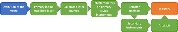
Figure 1. Flowchart of the typical traceability infrastructure. Reprinted from [14], Copyright (2015), with permission from Elsevier.
Download figure:
Standard image High-resolution imageThe current specification standard ISO 25178 part 70 encompasses the material measures previously listed in ISO 5436 part 1, albeit under different names, together with the newer ones used for the calibration of areal instruments [13]. However, the current iteration of the standard focuses on three main areas of application: the calibration of the scales of an instrument, calibration of the topographic spatial resolution and for overall instrument performance verification [18].
- Calibration of the scales: The calibration of the scales of an instrument is achieved with the determination of the metrological characteristics of noise, flatness, amplification, linearity and squareness of the scales [12]. The default methods for determining the metrological characteristics along with the associated measurement methodologies are presented in [19, 20], which were later developed into the National Physical Laboratory (NPL) good practice guides e.g. the coherence scanning interferometry good practice guide [21].
- Topographic spatial resolution: Topographic spatial resolution describes the ability of a surface topography measuring instrument to distinguish closely spaced surface features [11]. Based on the method of measurement and the application, a number of different criteria are available for the characterisation of topographic spatial resolution (listed in ISO 25178 part 600). Example material measures include several periodic and a star-shaped material measure [12]. Though not included in ISO 25178 part 70, chirped artefacts can also be used to characterise topographic spatial resolution [22].
- Overall instrument performance: Despite the fact that the metrological characteristics allow for the evaluation of uncertainty for specific measurement tasks, it is also of benefit to have material measures that can be used to check the overall instrument performance by characterising a number of areal surface texture parameters as found in ISO 25178 part 2 [23, 24].
Table 1 shows the metrological characteristics and the main potential error along the axes of the instrument they influence [11]. The propagation of the metrological characteristics through a specific measurement model allows for the evaluation of measurement uncertainty [12]. This review presents the state of the art on material measures for the determination of the metrological characteristics and overall instrument performance, focusing on their design and fabrication.
Table 1. List of metrological characteristics, their assigned mathematical symbols and the primary measurement instrument axis along which they act. Here, x and y represent the horizontal axes of the measured surfaces and z represents the vertical axis. Reproduced from [12]. © The Author(s). Published by IOP Publishing Ltd CC BY 4.0.
| Metrological characteristic | Symbol | Main potential error along |
|---|---|---|
| Measurement noise |

| z |
| Flatness deviation |

| z |
| Amplification coefficient |
 , ,  , , 
| x, y, z |
| Linearity deviation |
 , ,  , , 
| x, y, z |
| X–y mapping deviation |
 (x, y), (x, y),  (x, y) (x, y) | x, y |
| Topographic spatial resolution |

| z |
| Topography fidelity |

| x, y, z |
2. Material measures for the determination of measurement noise and flatness deviation
In ISO 25178 part 600 measurement noise is defined as the 'noise added to the output signal occurring during the normal use of the instrument' while flatness deviation is defined as the 'deviation of the measured topography from an ideal plane'. The default material measure used for the determination of both metrological characteristics is a type areal flat plane (AFL) and an optical flat is commonly used [24]. The optical flat is considered as a flat plane with negligible form deviation. The degree of flatness is determined by the maximum peak-to-valley deviation and is often expressed as a fraction of a reference wavelength of light (λ = 632.8 nm). Commercially available optical flats have a degree of flatness ranging from λ/4 down to λ/20 [25]. Optical flats are predominately manufactured from polished glass, fused silica and metals as they are mechanically hard and have relatively low coefficients of thermal expansion. The reflection factor of an optical flat changes based on the material from which it is manufactured. Depending on the measuring principle and instrument used, the reflectivity of the material may influence the measurement noise [26]. In contrast to other optical technologies, in general, focus variation is unable to measure optically flat surfaces, due to the requirement for at least some contrast in the focus image. This limitation is circumvented by use of a slightly roughened (nanoscale roughness) flat or by using newer iterations of focus variation instruments (as they use a combination of illumination, control of sensor parameters and integrated polarization to measure smooth surfaces) [27, 28].
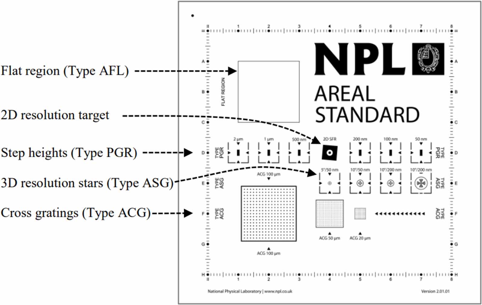
The fabrication of a flat begins with some raw material which is roughly cut into shape using a computer numerical control (CNC) machine. The final shape of the surface is generated through a grinding process. Finally, the desired degree of surface flatness is achieved through a polishing process. The surface quality of a fabricated flat is often assessed by interferometry by comparison to a master optical flat [29]. Both the reference surface as well as every optical element within the interferometer must be of high enough quality so that the only influence factor that affects the interference pattern is the surface being tested [30]. Optical flats are commercially available at different degrees of surface flatness from several different manufacturers, whereas type AFL material measures are available as standalone material measures or as part of a calibration set, such as the NPL areal artefact shown in figure 2 [31].
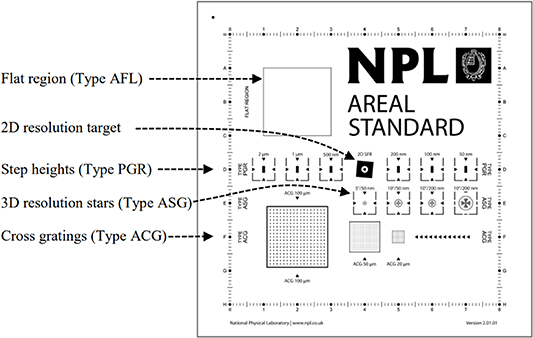
Figure 2. Diagram of the NPL areal standard. Reproduced with permission from [31].
Download figure:
Standard image High-resolution image3. Material measures for the determination of the amplification and linearity of the axes
The amplification and linearity of the axes is encompassed in three metrological characteristics, namely amplification coefficient, linearity deviation and x–y mapping deviation [32, 33]. The following definitions are from ISO 25178 part 600.
- Amplification coefficient: 'Slope of the linear regression line obtained from the response function'.
- Linearity deviation: 'Maximum local difference between the line from which the amplification coefficient is derived and the response function'.
- X–y mapping deviation: 'Gridded image of x- and y- deviations of actual coordinate positions on a surface from their nominal positions'.
The calibration of the metrological characteristics of amplification and linearity reflects the uncertainty of a number of different influence quantities, listed in detail in the ISO 25178 part 60X series [3–9]. Unlike the MCs of measurement noise and flatness deviation, these characteristics are properties of the instrument and as such, their corresponding uncertainty contribution is independent of the surface being measured. In terms of values, the amplification coefficient is characterised by a single number; its deviation from unity while linearity is given as a function of the corresponding axis coordinate [12].
3.1. Step height material measures
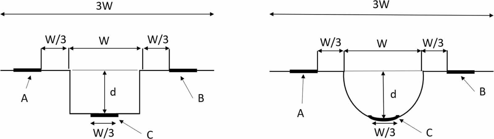
The default method used for the determination of the metrological characteristics of amplification and linearity in the axial direction is to use several step height material measures either of type profile groove rectangular (PGR) or type profile groove circular (PGC) [34, 35]. According to ISO 25178-70, the geometry of these material measures includes a wide groove or grooves of increasing depth with a flat or rounded bottom as shown in figure 3, with each groove being wide enough to disregard any limitations about the lateral resolution of the instrument (such as the tip of a stylus instrument) [13]. The reason for multiple grooves is because the use of a single step height material measure does not provide enough information about the response curve of the instrument. Therefore, several different step height material measures covering the working range of the instrument need to be employed to provide a more accurate model of the relationship between the ideal response curve and the instrument response curve. Consequently, due to the finite number of step height material measures available, the determination of the amplification coefficient and linearity deviation is achieved through interpolation of the measured data from the step heights.
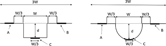
Figure 3. Left: diagram of the type PGR material measure, right: type PGC material measure. The areas of interest are 'A', 'B' and 'C'. The value of interest is 'd' and is calculated as the difference of 'A' or 'B' from 'C'. Reproduced with permission from [13].
Download figure:
Standard image High-resolution imageThe common methods for fabricating a step height material measure include film deposition and/or surface etching [36]. Film deposition involves the deposition of aluminium oxide on a monocrystalline silicon substrate [37]. The deposition continues until the film reaches the desired thickness. The grooves of the material measure are then formed through a combination of photolithography and wet etching. Photolithography uses light as a means of transferring a geometric pattern from a photomask on to a substrate [38]. A thin layer of a photoresist is applied on top of the substrate which when exposed to light breaks down. The photoresist residue is then removed using an organic solvent leaving the remainder of the photoresist with the pattern of the mask. Then, using wet etching, the exposed areas of the aluminium film are chemically removed. Finally, the remainder of the photoresist is removed leaving the etched pattern on the substrate creating the material measure. Chenying et al applied the photoresist fabrication process for the creation of three different step heights with nominal step height values of 8 nm, 18 nm and 44 nm [36]. The three step height material measures calibrated by Physikalisch-Technische Bundesanstalt (PTB) using atomic force microscopy (AFM) exhibited Ra values of 0.2 nm for both the upper and bottom surfaces with only small errors between the step height values and the thickness of the aluminium oxide film. Essentially, the quality of the step height produced is dependent on the optimisation of the fabrication process. However, the design of step height material measures may introduce several errors in the measurement either due to different materials being used for its fabrication or due to the non-uniformity of the step. Different materials have different mechanical and optical properties which depending on the material may introduce errors for both contact and optical instruments [39, 40]. In areal measurements, the effect of the non-uniformity of the step height can be reduced through the application of the ISO 5436-1 analysis which expresses the height measurement as a mean of several profiles.
The non-linearities of the vertical axis and the variety of the working range between instruments have resulted in a demand for different step height material measures that can provide axial axis traceability. VLSI Standards Inc. offers a variety of step height material measures with nominal heights ranging from 8 nm to 250μm which are traceable to the definition of the metre through National Institute of Standards and Technology calibrated artefacts [41–43]. Rubert & Co Ltd also offers a set of material measures for step height calibration, albeit as a type areal cross grating (ACG) instead of the standard PGR [44]. The material measures are part of an areal traceability infrastructure developed by NPL [45]. The type ACG material measures offered by Rubert are reproduced using galvanic replication, a process similar to electroforming, and are traceable to the definition of the metre using a primary stylus instrument available at NPL fitted with laser interferometry [45]. Multiple step height material measures are also commercially available. Halle offers two different material measures of either type PGR or type PGC equipped with six grooves of nominal heights 0.25 μm, 0.6 μm, 1 μm, 3 μm, 6 μm and 9 μm which are calibrated directly by PTB or through an unbroken calibration chain leading to PTB [46, 47]. Mahr also offers a set of multiple step PGR material measures at different groove depths which are also traceable through the primary measuring instrument at PTB [48].
However, other step height material measures are available which deviate from the default geometry found in ISO 25178 part 70. The material measure displayed in figure 4 developed by SiMETRICS and labelled Vertical Standard by the manufacturer is a step height material measure equipped with several structures [49]. Even though the overall layout differs from that of a conventional type PGR material measure, it can still be used for the calibration of the amplification and linearity in the axial direction. In detail, there are three different grooves of the same depth which can be used for calibration purposes. Additionally, a 25 groove structure is found on the upper part of the material measure which can be used for positioning purposes while also functioning as steps for calibration purposes. The material measure is available at three different depth ranges which can be found in table 2 along with their respective manufacturing methods.
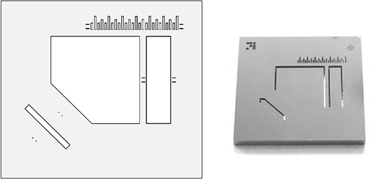
Figure 4. Etch mask of the vertical standard developed by SiMETRICS. Reproduced with permission from [49].
Download figure:
Standard image High-resolution imageTable 2. Depth ranges and the corresponding manufacturing method for the step height artefact developed by SiMETRICS.
| Depth (μm) | Manufacturing method | |
|---|---|---|
| Depth range 1 | 0.05–0.4 | Oxidation |
| Depth range 2 | 1–10 | Wet etching |
| Depth range 3 | 0.05–0.45 | Wet etching |
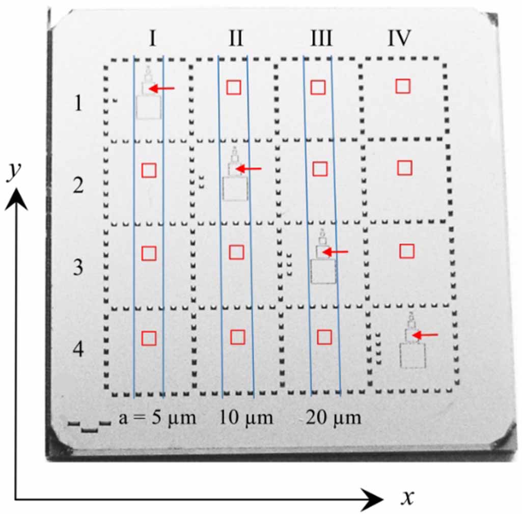
The material measure is available with a PTB calibration certificate or a calibration certificate by SiMETRICS. Yang et al developed a three-step step height material measure which is shown in figure 5 for the calibration of AFM instruments with heights of 8 nm, 18 nm and 26 nm [50]. As can be seen in figure 5, the material measure is fitted with several guiding arrows whose purpose is to point towards the indicated grooves used for the calibration of the instrument. The geometry of the left part of the material measure can be used for single step calibration while the right side is used for multistep calibration.
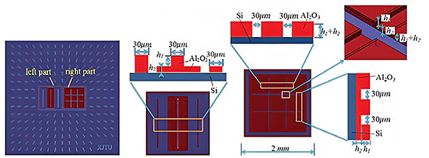
Figure 5. Schematic of the three-step height sample. Reproduced from [50]. © IOP Publishing Ltd. All rights reserved.
Download figure:
Standard image High-resolution imageDue to the large field of view of large-scale coherence scanning interferometer (CSI) instruments, calibration with conventional step height material measures is not feasible, as they do not cover the entire working range of the instrument and the step size is not appropriate for evaluation. Consequently, Boedecker et al developed a set of material measures that can capture the 70 mm working range of CSI instruments [51]. The material measures, which are depicted in figure 6, are manufactured from a high-grade steel suitable for precision machining. Each of the annular surfaces was fabricated using a combination of grinding and lapping. The coarse step height material measure has a total of 19 steps equally spaced to cover the 70 mm working range of the interferometer, which results in a difference of 3.75 mm between each surface. To account for the non-linearities of the z-axis not captured by the coarse one, a second material measure was developed with the same number of steps, albeit at a smaller spacing of 0.295 mm [51]. Due to the geometry of the coarse sample, conventional calibration using a primary stylus instrument was not feasible, as their vertical dynamic range is limited compared to the height of the material measure and as such a high precision coordinate measuring machine (CMM) was used [51].
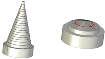
Figure 6. Left: model of the coarse step height material measure, right: fine step height material measure. Reproduced from [51]. © IOP Publishing Ltd. CC BY 3.0.
Download figure:
Standard image High-resolution imageThe smallest commercially available step height material measure manufactured with conventional fabrication processes is approximately 8 nm, which leaves a gap in the availability of material measures below that height. Most optical instruments are unaffected by this gap as their working range is covered by the currently available artefacts. However, AFM instruments used in industrial applications, such as the semiconductor industry, require such material measures in order to establish traceability [52]. Two materials have been developed in order to address this need. The first of the two is a step height artefact consisting of lattice steps on a single crystal Si (111) surface prepared in an ultra-high vacuum environment [53]. The material measure has a nominal height of 0.314 nm and an accuracy of approximately 6% [54]. The second developed by Vorburger et al (2010) is a 1 nm step height material measure fabricated using deep etching and epitaxial deposition, a process similar to film deposition, on a polished SiC substrate [55]. Measurements of the material measure using a calibrated AFM instrument yielded an average step height value of 0.981 nm with a combined uncertainty of 0.019 nm. Like the semiconductor industry, the bioscience sector requires traceable measurements of bio-samples featuring dimensions less than 10 nm [56]. Moreover, typical calibration material measures differ optically from bio-samples as they create a phase change in the light upon transmission and reflection which introduces errors in the measurement process. Heikkinen et al introduced a set of material measures fabricated based on the principles of self-assembly [56]. The manufacture of these artefacts is achieved with the use the Langmuir–Blodgett deposition process. The technique involves the deposition of a substrate into an air–water interface where a monolayer of stearic acid has been spread. The interface is compressed until the monolayer reaches the solid phase. Once this occurs, the substrate is lifted at a constant speed from the interface while also keeping the pressure of the interface constant. The process repeats for the next layer, albeit that the substrate is partially submerged into the interface in order to create the subsequent layers as seen in figure 7. The segment that was not submerged would constitute one of the steps of the artefact.
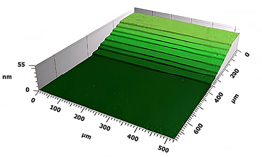
Figure 7. 3D image of Langmuir–Blodgett films-based material measure. Reproduced from [56]. © IOP Publishing Ltd CC BY 4.0.
Download figure:
Standard image High-resolution imageA second step height artefact, manufactured using the Langmuir-Blodgett deposition process, was fabricated by submerging the substrate in the water-air interface at the two diagonals, with the design shown in figure 8(a), to create three different heights for the sample. Calibration of the samples was achieved using an AFM instrument calibrated using step height artefacts traceable to a primary metrological AFM located at VTT Mikes [57]. The results of the calibration of the second sample using a CSI instrument yielded a standard uncertainty of 0.3 nm for a nominal step height of 5.4 nm. The measurements of the first material measure also exhibited similar levels of uncertainty for all eight steps. A histogram method was used to quantify the uniformity of the steps for the self-assembly technique. The results of the histogram showed a variation for width of the steps from 0.18 nm to 0.35 nm with a standard deviation of 0.03 nm.
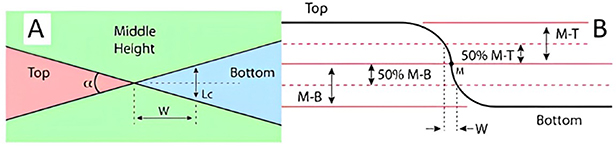
Figure 8. Schematic and profile crossing of the NanoStar sample. Reproduced from [56]. © IOP Publishing Ltd. CC BY 4.0.
Download figure:
Standard image High-resolution imageAn alternative to using a step height material measure for vertical scale calibration involves the use of a multiple delta-layer film artefact [58]. The multi-layer artefact, which consists of 12 alternating layers of Si and Ge, is manufactured with a technique called ion beam sputter deposition. The artefact is equipped with six craters of increasing depth, which can be used for the calibration of the vertical scale of stylus instruments. Similarly, Eifler et al developed a method that can be used for the calibration of the amplification coefficient and linearity deviation in the axial direction [59]. The method is based on the determination of the Abbot-Firestone curve for a 'transformed' commercial roughness artefact. In this context, the transformation corresponds to the machining of the artefact via an ultra-precision turning process so its Abbot-Firestone curve closely matches the theoretical one. By examining the Abbot-Firestone curve of the transformed artefact, the amplification and linearity in the axial direction can then be evaluated. The advantage of using the modified roughness artefact is the almost stepless calibration of the vertical axis, which only limited by the spatial discretisation of the measured profile.
3.2. Cross grating material measures
The amplification, linearity and perpendicularity of the x and y axis of an instrument can be calibrated with the use of a type ACG material measure. As defined in ISO 25178 part 70, the material measure has a two-dimensional array pattern that is composed of lines, grooves or dots. To account for the field of view of different magnification objectives, the cross grating arrays are available at different pitches ranging from 16 μm to 400 μm [44]. Moreover, the different patterns are fabricated at different heights also allowing the use of the material measure for the calibration of the amplification coefficient and linearity deviation in the axial direction.
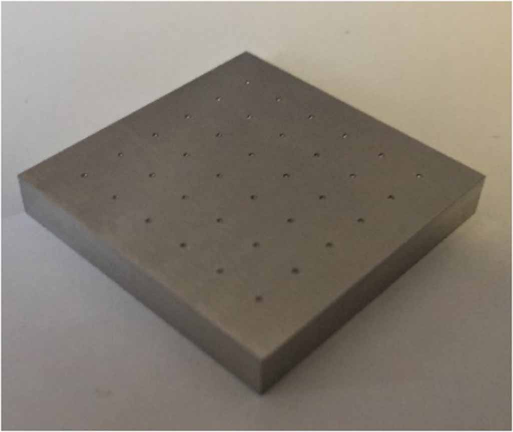
One manufacturing process for type ACG material measures uses a combination of e-beam lithography, metallisation and electroforming [45]. E-beam lithography is a fabrication process that uses a focused electron beam to expose the pattern on the substrate based on serial exposure [60]. The second step of the process is metallisation using chromium and gold. Chromium was used to act as an adhesive between the substrate and the gold layer, while gold was used due to its conductive properties for the creation of the moulding tool of the material measure. The replication was carried out with nickel electroforming. The metallised master created with lithography was subjected to a bath of boric acid which contained nickel sulphamate electrolyte. The nickel shims developed using the methods were replicated using galvanic replication, a process similar to electroforming, described previously. Leach et al used a CSI instrument to characterise the step height capabilities of several different cross grating material measures which, despite large form errors on the sample, the standard deviation of the mean was found to be less than 1.1 nm [45]. A number of type ACG material measures are commercially available from Rubert & Co as part of the NPL areal traceability infrastructure [24]. Additionally, both NPL and PTB include type ACG material measures with their areal calibration standards. Each of the standards includes gratings of different dimensions, as seen in table 3. However, as it is with many of the commercially available optical flats, a number of focus variation microscopes are not able to measure some of the type ACG artefacts as they are too smooth for the instrument [27]. Consequently, a variation of the type ACG was developed which features hemispherical grooves arranged in a six by six grid pattern. The material measure illustrated in figure 9 is manufactured from stainless steel using a combination of high-precision micro-milling and lapping, resulting in surface topography that favours the use of a focus variation microscopes. Calibration of this material measure is carried out using a CMM [61].
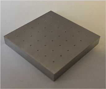
Figure 9. Cross grating material measure with hemispherical grooves. Reproduced from [61]. © IOP Publishing Ltd. CC BY 3.0.
Download figure:
Standard image High-resolution imageTable 3. Type ACG material measure dimensions for the NPL areal standard and universal calibration artefact [31, 62].
| NPL areal standard | ||||
|---|---|---|---|---|
| Dimensions (μm) | 25 × 25 | 50 × 50 | 100 × 100 | |
| Universal calibration artefact | ||||
| Dimensions (μm) | 100 × 100 | 200 × 200 | 400 × 400 | 800 × 800 |
| Available depths (μm) | 0.03 | 0.5 | 1.2 | 2.1 |
Dai et al introduced two different approaches for the calibration of the 1D gratings: a gravity centre method and a Fourier transform method [63]. The gravity centre method involves the determination of the centre of gravity of each grating with the help of three lines crossing the gratings at the top and bottom of their structure and at an arbitrary location chosen by the user [64, 65]. The points the threshold line intersects with each structure are used to calculate their corresponding centres of gravity. Then, using the centre of gravity of each structure both the mean pitch and position deviation curve of the grating can be determined. The Fourier transform method involves the calculation of the spatial frequency of the grating in the spectral domain. The value of the mean pitch can be calculated by  where
where  corresponds to the maximum amplitude of the frequency spectrum. The two methods are also applicable for 2D gratings. However, calibration of each structure on a 2D grating, though feasible, is a very time-consuming process [66]. The measurement strategy overcomes this limitation by scanning the artefact at three different measurement areas. The first area is used to obtain a detailed topographical view of the grating while the other two are used for the calculation of the mean pitch and pitch uniformity along the x and y axes [67].
4. Material measures for the determination of topographic spatial resolution and overall instrument performance
ISO 25178 part 600 defines topographic spatial resolution as the 'metrological characteristic describing the ability of a surface topography measuring instrument to distinguish closely spaced surface features'. In comparison to the previous metrological characteristics, topographic spatial resolution is a qualitative term which encompasses several different criterions used to describe the resolution of an instrument based on the instrument and surface type being used. Consequently, each of the criterions can be realised by their associated material measures. For instance, resolution for imaging systems is commonly defined either using the Rayleigh or Sparrow criterions which assess the ability of a system to distinguish between two point-like features [68–70]. Both the Rayleigh and Sparrow criterions can be determined with the use of grating material measures such as those illustrated in figure 10; an overview of which is given below:
- Type periodic sinusoidal structure (PPS): The structure of the material measure includes a sinusoidal shape along one direction with its shape defined by a period p and amplitude d. The material measure must have enough spacing to check the transmission characteristics of an instrument. A number of type PPS material measures are commercially available from Rubert & Co Ltd [44] and Simetrics [71].
- Type periodic rectangular structure (PPR): The material measure is a shaped grating artefact like a type PPS but with rectangular grooves. The form of the material measure is defined by three different measurands, namely the groove width w, the shape period p and the groove depth d. Simetrics offers a calibrated type PPR material measure manufactured with wet or dry etching [72].

Figure 10. Left: schematic of the type PPS, right: schematic of the type PPR. Reproduced with permission from [13].
Download figure:
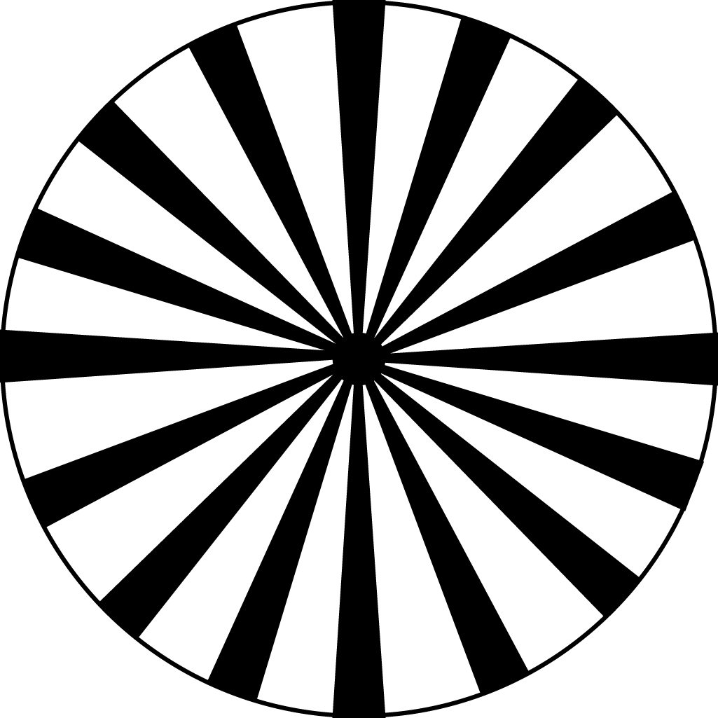
Standard image High-resolution imageThe shaped grating material measures are fabricated with etching and are either made using nickel or silicon [73–75]. For surface topography measuring instruments, the quantitative criterions that comprise topographic spatial resolution are lateral period limit, lateral resolution and width limit for full height transmission. According to ISO 25178 part 600, lateral period limit is defined as 'spatial period of a sinusoidal profile at which the height response of an instrument falls to 50%' [11]. A method of estimating the lateral period limit is to use a type areal star groove (ASG) material measure. The material measure is an adaptation of the Siemens star used for the investigation of focus on cameras [76]. The dark and light branches of the schematic seen in figure 11 are replaced with peaks and valleys [77, 78]. The process of estimating the lateral period limit is outlined in the NPL good practice guides [21] and involves two measurements along the radius of two consecutive grooves of the material measure. The lateral resolution can also be evaluated with the use of the material measure as the grooves continue to decrease in width as they converge towards the centre of the material measure to an area labelled as the ambiguous region. The significance of the region is that the instrument being calibrated cannot identify the alteration of grooves, and hence by estimating the diameter of the region, the lateral resolution of the instrument can be determined. However, unlike other material measures with stated calibrated measurands, type ASG do not have reference values, as resolution is an instrument dependent characteristic. The distribution of the lateral period limit has been investigated by Eifler et al. In their work, three different type ASG material measures were measured by five different instruments with values ranging from 3 μm to 5 μm [22]. The repeatability of the material measures was also investigated as the variance between the extracted profiles contributes to measurement uncertainty. Though the values of the repeatability test followed the same trend ranging from 3.5 μm to 5.5 μm [62]. Misidentification of the ambiguous region for a type ASG material measure can result in deviations of the lateral period limit value. In their correlation study, Schaude et al [79] determined that offsetting the centre of the ambiguous region in both x and y by up to 0.1 μm can result in deviations of the lateral period limit of up to 20 %. However, a modified version of the good practice guide [21] approach allows for a more accurate determination of the centre of the ambiguous region. This process involves the measurement the material measure radially, at a location where the structures are resolved, followed by the determination of the phase of the structures via a Fourier series approximation. Finally, by conducting a series of measurements with a small offset along the direction of the phase, the centre of the ambiguous region is identified by the lines having the smallest lateral period limit. Though the application of the technique improves the evaluation of the lateral period limit, when compared to the good practice guide approach, it requires access to the raw data from the instrument.

Figure 11. Schematic of the type ASG material measure. Reproduced with permission from [13].
Download figure:
Standard image High-resolution imageA surface can be represented by a finite number of sinusoidal oscillations of certain amplitude and wavelength. However, as surface topography measuring instruments operate within a certain bandwidth of spatial frequencies, they may not be able to correctly measure a surface as certain spatial frequencies are either partly measured or not measured at all [80]. In ISO 25178 part 600 the term instrument transfer function (ITF) is defined as 'curve describing an instrument's height response as a function of the spatial frequency of the surface topography' [11]. Fujii et al developed a measurement artefact composed of sinusoidal waveforms of increasing spatial frequency that allows for the verification of an instrument's ITF [81]. As the local slope of the facet influences the response curve of the instrument, the magnitude of the waveforms gradually decreases at the rate which keeps the local slope constant. The material measure illustrated in figure 12 was fabricated using a focused ion beam and calibrated using an AFM. A laser scanning microscope was used to measure the different combinations of wavelength and slope angles of the material measure. The response curves of the instrument exhibited a drop in amplitude as the wavelength decreased. However, for angles of 35° degrees and higher the response curves were affected by spike errors attributed to the increasing surface gradient [82].
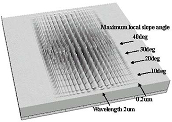
Figure 12. Schematic representation of the chirp artefact. The maximum local slope angle along the lateral direction varies up to 45°. Reproduced from [81]. © IOP Publishing Ltd. CC BY 3.0.
Download figure:
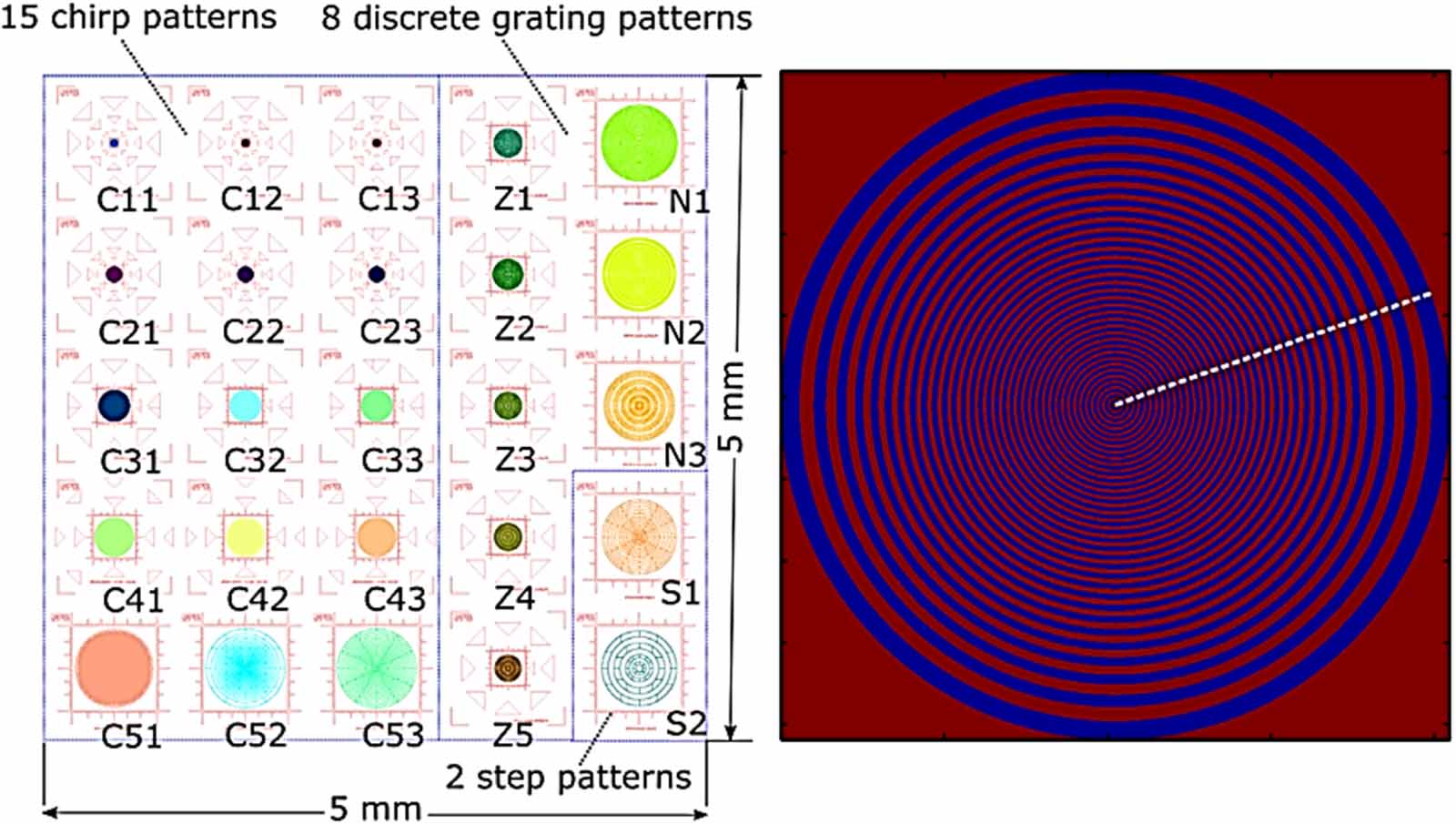
Standard image High-resolution imageA similar approach to the chirp artefact has been used by Dai et al [83]. The material measure expands upon the characterisation of an ITF [84] by the circular structure design of its patterns. The circular design can be used for the characterisation of the ITF in different angular directions allowing for the characterisation of angular-dependent asymmetries of an instrument. The material measure consists of three different groups of patterns including chirp, circular discrete and circular step patterns for a total of 25 patterns. As can be seen in figure 13, all the patterns are circular and are equipped with navigation marks in order to easily identify the measurement area. Moreover, each of the patterns has a different external radius in order to accommodate for different magnifications and different spatial wavelength ranges for the characterisation of the ITF. The material measure is manufactured using e-beam lithography, the wafer is made from sapphire and the structure patterns from gold-palladium. It is calibrated by a primary AFM instrument [83].
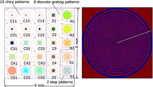
Figure 13. Left: layout of the CSS material measure, right: detailed layout of a single pattern Reproduced from [83]. © IOP Publishing Ltd. All rights reserved.
Download figure:
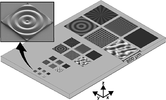
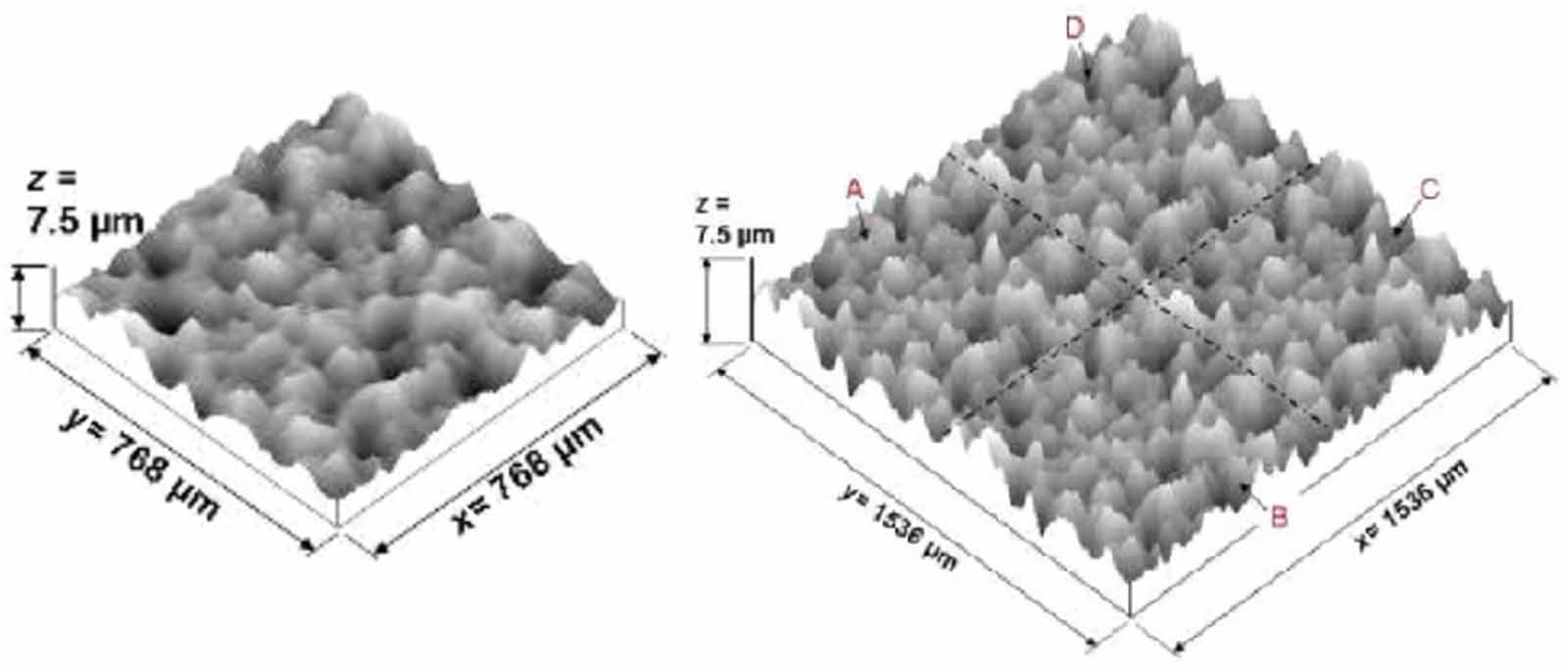
Standard image High-resolution imageThe type areal irregular (AIR) [85, 86] material measure is an artefact consisting of a limited range of wavelength components that aims to quantify the overall performance of optical and tactile instruments. Like a type D artefact, the type AIR is characterised by several surface texture parameters such as Sq, Sz, Ssk and Sku. Uchidate et al developed such a material measure based on a non-casual 2D auto-regressive (AR) model [87]. Essentially based on several generation parameters acting as inputs for the AR model a 2D height distribution is generated. In their work, Nemoto et al developed two different material measures labelled as B40 and B70 based on their nominal autocorrelation lengths of 40 μm and 70 μm respectively. The replication capabilities of the material measures were investigated by Leach et al as the cost of manufacturing them using precision machining is high [88]. A sampling area of the material measure can be seen in figure 14.

Figure 14. Left: type AIR sampling area, right: type AIR multiple sampling areas. Reproduced with permission from [13].
Download figure:
Standard image High-resolution imageUsing the same 2D height distribution, two different master artefacts were created by diamond ball end-milling on a five axis ultra-precision machine tool. The replication process was done using nickel electroforming. The quality of the produced artefacts was tested by a primary contact stylus areal surface instrument and a commercial CSI instrument. The measured value of the Sq parameter for the two instruments was in good agreement with the nominal Sq value of the designed surface. The material measures are commercially available by Rubert & Co Ltd and are also part of the NPL areal traceability infrastructure [24]. Another approach to a type AIR material measure was introduced by Frühauf [89]. Contrary to using an AR model, the material measure was developed with the use of a stochastic manufacturing process. The material measure is a silicon chip comprised of a 4 × 4 array of measurement areas, as can be seen in figure 15. A lapping process on SiC was performed to each of the active areas in order to produce the irregular surface texture. Grooves of increasing spatial frequency are scratched to each of the columns aside from the last one in order to introduce an anisotropic component to the texture of the surface. Marks for positioning are also created using either lithography or etching. Additionally, along the diagonal, five additional patterns are created in order to frame the measurement area for measurements using interferometric, confocal or AFM instruments. The inclusion of grooves for each group of fields allows for the determination of the two parameters defined in ISO 25178 part 2 not covered by the B40 and B70 material measures, namely the autocorrelation length Sal and the texture aspect ratio Str [90].
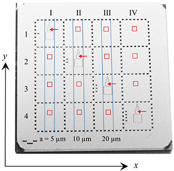
Figure 15. Illustration of the roughness standard developed by Simetrics. Reproduced from [89]. © IOP Publishing Ltd. All rights reserved.
Download figure:
Standard image High-resolution imageA type AIR material measure has been developed that can be used for the determination of the Sk parameters as found in ISO 25178 part 2. The manufacture of the material measure follows a two-stage closed loop process. The virtual aspect of the process revolves around a comparison of the Sk parameters of the original surface to the desired Sk parameters, followed by an iterative process of virtual manufacture and evaluation. Once the virtual parameters converge to the target ones within a defined threshold the transformation of the measured surface takes place using the manufacturing process the virtual model has been adapted to [91].
A number of material measures are listed in ISO 25178 part 70 that are not part of the metrological characteristics framework, but they are used for the calibration of the x and y axes of an instrument due to the high accuracy of their geometric features. These include:
- Type periodic double groove (PDG): It is a material measure composed of two grooves with the measurand of interest being the distance between them. In order to calibrate both the x and y axes of an instrument the material measure needs to be rotated.
- Type areal grooves perpendicular: It is a material measure composed of four grooves forming a rectangle. The distance between the grooves can be used for the calibration of both the x and y axes of the instrument.
- Type areal grooves circular (AGC): It is a material measure composed of a circular groove. The measurand of interest is the diameter of the groove defined by the intersection circle between the two flanks of the groove.
- Type areal plane-sphere (APS): The material measure is composed of a part of a sphere and a plane.
- Type areal hemisphere: The material measure consists of a hemisphere with the flat component of the wafer not being part of the material measure.
A number of the aforementioned material measures can be used for the calibration of the z dimension. These include the type PDG (depth of the two grooves), the type AGC (depth of the circular groove) and the type APS (distance between top of the sphere and the plane) [92]. ISO 25178 part 70 also lists two other types of material measures, namely the type areal radial sinusoidal (ARS) and type areal cross sinusoidal used for the calibration of areal roughness parameters. A type ARS material measure is available as part of the universal calibration sample developed by Eifler et al [93]. The sample fabricated using direct laser writing and lithography features several material measures which can be used for the determination of all the metrological characteristics [93]. The detailed layout of the artefact can be seen in figure 16. In addition to catering for the determination of the metrological characteristics with the inclusion of type ASG, type ACG, type AFL material measures, the artefact is also equipped with a type AIR, type ARS and a chirp material measure.
Figure 16. Illustration of the universal calibration artefact. Reprinted with permission from [93] © The Optical Society.
Download figure:
Standard image High-resolution image
5. Material measures for the determination of topography fidelity
The metrological characteristic of topography fidelity is defined in ISO 25178 part 600 as the 'closeness of agreement between a measured surface profile or measured topography and one whose uncertainties are insignificant by comparison' [11]. Though omitted in the formal definition, topography fidelity indicates the accuracy between two surfaces after the influence of the other metrological characteristics has been accounted for [12]. Despite the absence of both material measures and a standard method for determining fidelity, the common theme is to use a material measure close in shape to that of the surface being evaluated. After optimum alignment of the two surfaces, the topography difference is used to quantify fidelity using the surface texture parameters defined in ISO 25178 part 2 [90].
However, as the effects of topography fidelity may appear as systematic deviations based on the influence of local surface gradient or when a step discontinuity is present, there are methodologies that can be applied to quantify these effects using currently available material measures. VDI guideline 2655-1.3 [94] includes methodologies for determining slope dependent effects using spherical artefacts while other approaches include the use of a titled optical flat to determine the uncertainty contribution of local surface slopes [95]. A comparison study between four CSIs and a reference AFM microscope investigated the effect of surface gradient using type PPS material measures and the effect of step discontinuities using type PGR material measures [96].
The small scale fidelity limit is defined in ISO 25178 part 600 as the 'smallest lateral surface feature for which the reported topography parameters deviate from accepted values by less than specified amounts' [11]. Despite being related to topographic spatial resolution, small scale fidelity limit is used to describe the effects not captured by traditional transfer function approaches for resolution and can be determined using methods for quantifying topography fidelity [12, 97]. The lateral deviations attributed to the small scale fidelity limit are influenced by the local surface curvatures of the surface being measured and can be captured using chirp artefacts [22, 98]. An alternative to the use of reference metrology for the quantification of topography fidelity is the use of a virtual instrument [99], essentially a 'digital twin' of the physical instrument calibrated. The virtual instrument, which is based on physical models derived from first principles, allows for uncertainty evaluation using a stochastic model which considers the influence factors (metrological characteristics) and through simulation mimics the real measurement process [100–102].
6. Material measures and uncertainty propagation
The relationship between traceability and material measures has been briefly explored in the introductory section of this work. A typical traceability infrastructure involves the use of material measures for the calibration of instruments used in industrial applications. In turn, material measures are calibrated by a primary instrument located in one of the national measurement institutes (NMIs), the axes of which are calibrated by a primary iodine stabilised laser to the definition of the metre [14]. However, as the definition of traceability states, the unbroken chain of calibrations requires a statement of the contributions to the measurement uncertainty. VIM defines measurement uncertainty as the 'non-negative parameter characterizing the dispersion of the quantity values being attributed to a measurand, based on the information used' [1]. The evaluation of the metrological characteristics is achieved with the use of material measures. However, as a material measure is either directly or indirectly calibrated by a primary instrument located in one of the NMIs, the contribution to the uncertainty of said instrument needs to be taken into consideration [97]. Given that the traceability infrastructure for profile material measures has been well established in the ISO 5436 series and ISO 12179, the majority of the NMIs are equipped with primary or secondary instrument that can be used to calibrate them [103–105]. On the other hand, areal traceability is still at its infancy and as a result only a handful of NMIs provide calibration services for areal surface texture measurement [106–108]. One such instrument, located at NPL, is a contact stylus instrument equipped with laser interferometers used to monitor the position of the stylus tip on the three axes of the instrument. In order to establish the traceability to the definition of the metre, Giusca et al evaluated the uncertainty of the scales of the instrument based on a mathematical model used to describe its geometry and functionality using the input–output model of the Monte Carlo approach (squareness of the axes, flatness of the reflecting mirrors, orientation of the interferometers). The outcome of the results demonstrated nanometre level uncertainties for the three axes of the instrument [109].
The calibration certificate of a material measure is proof of the establishment of traceability between the material measure and the primary or secondary instrument used to calibrate it. In accordance with Guide to the expression of Uncertainty in Measurement, the expanded uncertainty of a measurand is expressed as a large fraction of the distribution of values it is likely to take [110]. A calibration certificate documents the expanded uncertainty, reflecting the different sources of error associated with the instrument used for the calibration of the material measure. An example on how the uncertainty of a primary instrument is propagated in the traceability chain is demonstrated in the CSI good practice guide where the combined uncertainty of a step height material measure is described [21]. The uncertainty of the primary instrument is quadratically added together with the other sources of uncertainty for the material measure (error, repeatability, and reproducibility) [21].
7. Conclusions
In this review, the importance of material measures for establishing instrument traceability based on the ISO 25178 part 600 metrological characteristics framework has been discussed. The main characteristics of the currently available material measures, their geometry and fabrication process have been investigated. Considering the recent CIRP keynote on dimensional artefacts, it is evident that artefacts are and will continue to remain an essential link along the traceability chain from the SI unit of length to quality control in production [111]. However, there are still needs that have to be addressed for dimensional micro- and nano-scale metrology to progress:
- Given the broad range covered by surface measuring instruments there is still limited availability of material measures in the nanometre range [112].
- There is still need for the development of both a method and material measure(s) for the determination of topography fidelity. Though there are artefacts, such as the chirp artefacts that aim to characterise certain features of fidelity, it seems unlikely that a single material measure can incorporate all different surface structures that comprise it [12]. Some fidelity terms that appear as systematic height deviations dependent on the surface slope of the measurement area are currently being investigated with the use of a CSI based virtual instrument [100].
- Material measures like the chirp artefact or more complex ones, such as the NPL areal artefact or the universal calibration artefact, are expensive and time consuming to manufacture and calibrate. These factors inhibit the industrial adoption of such material measures for establishing traceability of a measurement.
- Surface measuring instruments operate within different spatial frequency regimes. It is unlikely that a single instrument can cater for the measurement needs of a single workpiece due to the different length scales required for its measurements [111]. Hence, a multitude of instruments is required to perform said measurements which results in an increase for material measures to provide calibration and traceability.
Material measures are an integral part of evaluating measurement uncertainty using the metrological characteristics infrastructure. Though the incorporation of uncertainty alongside a surface topography measurement result is currently scarce, the publication of ISO 25178 part 700 [113] will further simplify the process for uncertainty evaluation allowing for the adoption of the metrological characteristics framework in industry.
Acknowledgments
The authors would like to thank UKRI Research England Development (RED) Fund for supporting this work via the Midlands Centre for Data-Driven Metrology and the Manufacturing Technology Centre (MTC).
Data availability statement
No new data were created or analysed in this study.