

Abstract
We present a design for a 4 U (20 cm × 20 cm × 10 cm) occultation-viewing laser heterodyne radiometer (LHR) that measures methane (CH4), carbon dioxide (CO2) and water vapor (H2O) in the limb that is designed for deployment on a 6 U CubeSat. The LHR design collects sunlight that has undergone absorption by the trace gas and mixes it with a distributive feedback (DFB) laser centered at 1640 nm that scans across CO2, CH4, and H2O absorption features. Upper troposphere/lower stratosphere measurements of these gases provide key inputs to stratospheric circulation models: measuring stratospheric circulation and its variability is essential for projecting how climate change will affect stratospheric ozone.
Export citation and abstract BibTeX RIS
1. Introduction
CubeSat instruments provide a unique and often underrated opportunity to make targeted atmospheric measurements at a significantly lower cost and faster turn-around than traditional flight instruments. Though the size limits imposed on a CubeSat payload (typically under 4 U7) were originally thought to severely limit the potential for a useful data product, the miniaturization and commercial availability of many laser components that have been brought on by growth of the telecommunications industry allows for construction of small and effective instrumentation.
Here we present the design of a passive, occultation-viewing, 4 U CubeSat laser heterodyne radiometer (LHR) instrument that measures CH4, CO2, and H2O in the limb that has been developed and built at NASA Goddard Space Flight Center and will be housed on a 6 U CubeSat bus developed and built at Lawrence Livermore National Laboratory (LLNL). Deployed in a low earth orbit (LEO), this instrument will be capable of observing the region between the upper troposphere to the lower stratosphere. Compared to current greenhouse gas observation satellites such as the greenhouse gas observing satellite (GOSAT) [1] and the orbiting carbon observatory-2 [2, 3] that measure the total column absorption of greenhouse gases in sunlight reflected from the Earth's surface, this CubeSat has much smaller payload, much lower cost and much higher spectral resolution which is appropriate to measure the narrower vibration-rotational lines in the upper air with lower atmospheric pressure. In addition, the LHR sun-pointing limb measurements in the upper air will have much less atmospheric scattering effect which has known to be the largest error in those satellite observations using surface reflected sunlight [4–6].
Measurements of CH4, CO2, and H2O from the upper troposphere to the middle stratosphere provide critical information on stratospheric circulation and how it responds to increasing greenhouse gas (GHG) concentrations. The circulation affects stratospheric temperature by controlling the distribution of radiatively important gases such as CH4, CO2, O3, and H2O, but also affects photochemistry through its impact on the distribution of gases that control O3 loss processes. Measuring stratospheric circulation and its variability is essential for projecting how climate change will affect stratospheric ozone.
The projected CH4 and CO2 increases in the 21st century will impact photochemical, dynamical, and radiative processes in the stratosphere. Increased CH4 results in increased stratospheric water vapor and OH production, directly impacting O3 loss by OH. Changes in stratospheric ozone lead to local temperature changes and produce a dynamical response. Methane is long-lived below the upper stratosphere (~5 hPa), and thus its distribution is controlled by seasonal and interannual variations in the strength of stratospheric circulation. Most chemistry climate models predict a speed-up of the stratospheric circulation in this century due to increasing GHGs [7]. Because of the methane's role in the changing chemistry of the ozone layer and because of its long lifetime, methane measurements are especially valuable to measuring composition change and for identifying and quantifying GHG-driven changes in stratospheric circulation.
2. Instrument design
The 4 U LHR presented here is based on a similar ground-based instrument that was developed at NASA Goddard Space Flight Center for measurements of CO2, CH4 and H2O in the atmospheric column [8–11]. Some changes in components were required to reduce the mass, volume and power of the LHR as well as to remove the use of problematic moving parts such as the optical chopper (replaced with an optical switch). What the 4 U instrument shares with the ground instrument is the use of low-cost, commercial, off-the-shelf telecommunications components. A challenge of using these components is that they are intended for use at the telecom wavelengths of ~1550 nm and not at 1640 nm where methane absorption features have strong enough line strengths to be measured in our atmosphere (CO2 and H2O absorption features in contrast also have good line strengths at lower wavelengths such as the 1570 nm region). For this reason, these components are often not operating at peak efficiency and it is likely that as the technology progresses, the performance of this design will also improve.
In the 4 U design shown in figure 1(a), collimation optics with a 0.2° field of view (Thorlabs part #F810APC-1550) point at the sun and collect light that has undergone absorption by methane in the limb. Collected sunlight is modulated with a fibre optic switch (CrystaLatch™, Agiltron part #CLSW-115231323) at 500 Hz and then launched into a 50/50 single-mode fibre coupler (Thorlabs part #10202A-50-APC) where it is superimposed with IR laser light from a distributive feedback (DFB) laser (Eblana photonics part #EP1653-7-DM-B01-FA). Laser light and sunlight are mixed in an InGaAs fast (>10 GHz) photoreceiver (Electro-Optical Technology model #ET-3500FCEXT/APC) to produce a beat signal in the radio frequency (RF) region. The RF receiver (custom) amplifies and detects the beat signal [8]. The resulting signal is measured with an analog lock-in amplifier (custom PCB) that is referenced to the fibre switch frequency. The analog output from the lock-in amplifier is scaled and converted to a digital signal through the microcontroller's (Freescale, model #MK20DX256) integrated 16 bit A/D converter. To scan an absorption feature, the microcontroller's external 16 bit D/A (analog devices AD5686) provides the laser controller (wavelength electronics part #LDTC2/2E-00000B) with a constant temperature set voltage and a sawtooth voltage to produce a changing laser current to repetitively scan the laser across the wavelength region of interest. The sawtooth voltage input to the laser, shown in more detail in figure 1(b), is a series of voltage steps that are taller at the start (α) and end (γ) of each line, and shorter at the center (β) of each line. This results in a higher scan resolution over the main body of the absorption feature where the curvature of the line is largest and a lower resolution over the wings as shown in figure 1(c). Each voltage step (corresponding to a wavelength of the laser) for example, could persist for 500 ms with the lock-in amplifier integrating for 250 ms. While the processor samples the signal from the lock-in continuously, only integrated points that fall on each wavelength step are ultimately averaged; meaning that if a data point has integrated a portion of the previous wavelength into the signal, this data point is not included in the averaged data for that wavelength. Figure 2 shows modeled spectroscopy of the 1640 nm region with simulated line transmittances at limb tangent heights of 6 km through 30 km [12].

Figure 1. In the 4 U LHR instrument design shown in (a), sunlight that has undergone absorption by the trace gas is modulated with a fibre switch and mixed with laser light in a fast photoreceiver. The resulting RF beat signal is amplified and detected in the RF receiver. An analog lock-in amplifier (referenced to the fibre switch frequency) detects the beat signal intensity as a voltage, converts it to a digital signal through the A/D (analog to digital converter), and then collects and averages it in the processor. To scan the laser, the processor sends voltage signals to the laser controller to (1) set the temperature and (2) step-scan the laser current (which corresponds to a laser wavelength, λ) through the line. The input to the laser controller is shown in (b) with the resulting absorption scan in (c). The spacing between laser wavelength steps is larger at the wings (α and γ) than at the center (β) of the line to maximize the resolution where the curvature of the line is the largest.
Download figure:
Standard image High-resolution image
Figure 2. Simulated transmittance for the occultation viewing LHR near 1640 nm shows H2O, CH4 and CO2 lines that are detectable at limb tangent heights between 6 km and 30 km.
Download figure:
Standard image High-resolution image3. Bus design
A 6 U CubeSat bus has been developed to support the 4 U payload that is based on the CubeSat next generation bus (CNGB) 3 U architecture and design. CNGB is being developed for the National Reconaissance Office (NRO) by a team led by LLNL, with significant contributions from the Naval Postgraduate School and the Space Dynamics Laboratory (SDL) at Utah State [13]. The bus is designed to be compatible with the Nanosatellite Launch Adapter System (NLAS) developed by NASA Ames Research Center and builds upon the CNGB mechanical, electrical and software standard. The 6 U bus with the 4 U LHR payload is shown in figure 3 and the spacecraft block diagram is shown in figure 4.
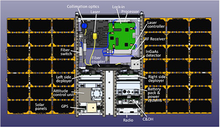
Figure 3. The 6 U CubeSat bus designed at LLNL supports up to a 4 U payload and controls command and data handling, electrical power, attitude determination and control, global positioning and communication. The 4 U LHR payload is shown at the top, center.
Download figure:
Standard image High-resolution image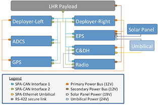
Figure 4. The 6 U CubeSat bus designed at LLNL supports up to a 4 U payload and controls command and data handling, electrical power, attitude determination and control, global positioning and communication. The 4 U LHR payload is shown at the top, center.
Download figure:
Standard image High-resolution image3.1. Command and data handling (C&DH)
The bus command and data handling (C&DH) is based on a 800 MHz Freescale i.MX537 ARM Cortex A-8 processor with 512 MB of dual data rate SDRAM and 128 MB of NAND Flash. The C&DH module also includes two 2 GB industrial grade SDCARD organized into a RAID 6 file system for storing telemetry and mission data. The C&DH module is also responsible for providing an Ethernet umbilical port for spacecraft data and configuration access on the ground. The bus uses two redundant CAN buses compliant with ISO-11898-1 and ISO-11898-2 with data rates at 1 MB s−1 and implementing the space plug and play avionics (SPA) [14] for CAN. The C&DH manages these two interfaces per the SPA and CNGB standard in the form of a link layer developed by SDL referred to as SSM (SPA Services manager) [15]. The C&DH also incorporates a flight software building upon the Modular Space Vehicle software developed originally by Northrup Grumman and further updated by SDL. This flight software takes full advantage of the SPA standard and incorporates the SSM software. The C&DH unit requires no more than 2.5 W of peak power and weight less than 100 g including the EMI shield for a 0.2 U equivalent volume.
3.2. Electric power system (EPS)
The bus electrical power system (EPS) is designed to deliver 70 Ah with a peak current of 7 amperes at 12 V. The EPS uses 6 NCR18650B lithium ion cells configured in 2 parallel strings of 3 cells in series. A cell balancing and battery management circuit ensures that over current, over and under voltage condition are handled to prevent damage to the battery pack. Charging can be done using an umbilical standard 19 V power supply of the two on orbit solar panels inputs via a maximum power point tracking circuit. Several inhibits are available including the standard separation switches but incorporating also a set of one time sun-sensor activated switches for orthogonal battery disconnection from the rest of the spacecraft. The EPS provides 2 power buses regulated at 12 V regardless of the state of the batteries. The primary bus is used for critical bus components, while the secondary bus is used for the payload and radio. (The radio generally requires additional protection against being accidentally turned on based on the launch opportunity.) Full telemetry of the battery pack and inhibit circuitry is available from the module. The module incorporates a heater with a 5 °C thermostat to maintain the lithium Ion cells within optimal operating conditions in case the spacecraft temperature is too low. The EPS weigh about 520 g including the enclosure for a 0.35 U equivalent volume.
The bus uses two deployable solar panels, each configured as a tri-fold panel, each fold containing seven 28.3% efficiency ultra triple junction (UTJ) solar cells. The two solar panels can provide up to 42 W of power at optimal orientation. Two commercial companies can provide tri-fold solar panels compatible with CNGB (Pumpkin Inc, and MMA, LLC) with the same performance described here. Power analysis for a typical 500 km orbit using these solar panels shows that for this mission the maximum depth of discharge per battery cell is less than 10%, with maximum occurring during data transmission while in the eclipse part of the orbit. This conservative maximum depth of discharge is consistent with 3750–4700 cycles prior to cell degradation and allows for at least 9 months of operation with nominal performances. The solar panel deployment system is fully resettable through a mechanical mechanism and does not make use of a one time restraining device. The bus has one deployment system per panel. The deployment system requires less than 0.4 W of peak power during the 5 s of deployment time and deployment status can be retrieved through telemetry as well as retried.
3.3. Attitude determination and control system (ADCS)
To maintain view of the sun during orbital observations, the CubeSat requires a pointing accuracy of at least 2 arcmin. The ADCS uses a commercial Blue Canyon XACT unit that provides sun pointing accuracy sufficient to maintain the 2 arcmin pointing accuracy requirement and 1 arcmin s−1 tracking rate. The unit can control the spacecraft using three reaction wheels, 3 magnetroquers, a quad cell sun sensor, inertial measurement units and magnetometers. A star tracker is also available to reach high tracking and pointing accuracy. A custom interface board has been added to the commercial unit to ensure compliance with the CNGB electrical and software standard, which allows direct control of power, high level telemetry as well as XACT specific commands. The XACT unit used for this bus is a version modified by the vendor to accommodate external GPS messages and has a modified enclosure to be mechanical compliant with the CNGB standard. The overall integrated ADCS module is slightly over 1000 g for a 0.7 U equivalent volume and is by far the largest sub-system in the bus.
3.4. Global positioning system (GPS)
This module enables the spacecraft position knowledge accuracy of a few meters. This module uses the OEM615 receiver from Novatel and requires no more than 1.4 W of peak power. A 35 mm L-Band patch antenna from Taoglas is used to receive the GPS signal and was demonstrated to provide reliable cold starts from the ground in less than 5 min. The GPS module can also be used as a pulse per second time source and tag to within 50 ns of UTC time any events on the bus with a use of a real time interrupt system. The overall integrated GPS module is less than 100 g with its EMI shield for a 0.18 U equivalent volume.
3.5. Radio communication system
The communication system is currently configured to make use of the iridium network and uses the Iridium 9523 modem over a circuit switched data link. Data rates of up to 2400 bps are expected to be achieved when the spacecraft is within the link sensitivity range of 1500 km and within the allowable Doppler shift velocity range of ±6 km s−1. An alternate solution using the Cadet S/U crosslink radio originally developed by L3 communication is being considered as a means to demonstrate an operational solution. This radio is using UHF 450 MHz for the uplink and a 2.2 GHz S-Band downlink with data rates of 1.6 MB s−1. The radio and accompanying software would be compatible with the mobile CubeSat command and control (MC3) ground station network developed by the Naval Research Laboratory for the NRO and could transition to a dedicated ground station for an operational system.
3.6. Environmental
To ensure the highest likelihood of mission success, the payload and bus have been designed to be compliant with the general environmental verification standard (GEVS). The preliminary environmental tests at the sub-system level show that the spacecraft will be compliant with launch requirements consistent with GEVS qualification levels. The thermal characteristics of the payload have been modeled using Thermal desktop (C&R Techologies®) to inform optimal thermal management on orbit, and will require the application of thermal blanket on sun facing and side surfaces and silver coated FEP (fluorinated ethylene propylene) tape (Sheldahl®) on the anti-sun surface. Analysis for a typical orbit in the presented spacecraft configuration has shown that the overall spacecraft temperature will vary from 5 °C to 45 °C throughout each orbit, which is consistent with the operational thermal range of −20 °C to +50 °C the spacecraft has been designed.
4. Orbit and observations
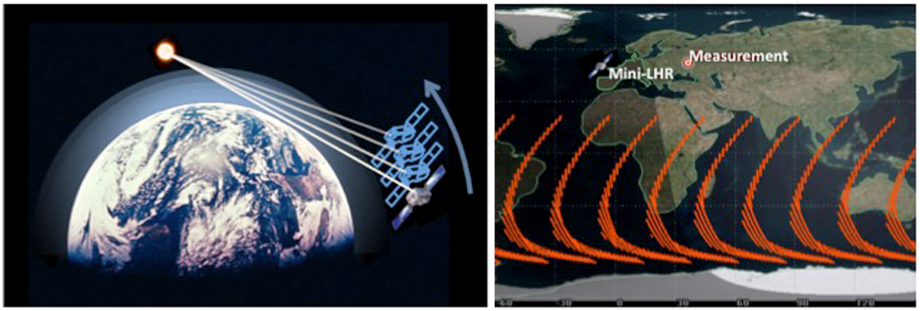
A one-year observation period following a high inclination orbit is projected to be utilized in this mission. This orbit will produce the longest data collection window for the occultation instrument as the observation path crosses the interface between night and day (terminator). The right side of figure 5 shows a graphical representation of the data that could be collected with an orbit similar to the ICESat-2 satellite [16]. This orbital path would produce continuous measurements for up to 530 s with an average duration of 120 s. During a 30 d period the instrument will capture a cumulative total 17.6 h of measurement data.

Figure 5. Left: in this sun-pointing instrument, high-inclination orbits provide lengthy observation times when the ascending node is oriented 90° from the sun (~1–4 min observations). Short observation times when the ascending node is oriented towards or 180° away from the sun (<30 s observations). Right: an orbital scenario for the mini-LHR as a secondary payload for a mission such as ICESat-2. Orange lines show measurement tracks for the first 30 d after launch.
Download figure:
Standard image High-resolution imageOrbits with high inclination typically allow for uninterrupted communication with the Iridium constellation with a downlink of 100–500 kB d−1. This cost effective approach is pay-per-use (data is exchanged over the internet) and removes the need for custom receiving infrastructure on the ground. The transceiver also allows for short burst transmissions of a few hundred bytes which are more likely to be transmitted in the case of orbital difficulties.
5. Analysis of observed data
Mole fractions are determined by fitting simulated limb measurements of a high spectral resolution radiative transfer model to LHR's absorption feature scans. Simulated transmittance, τν, at a wavenumber ν, is calculated with the Beer–Lambert law:

where υ is the mass path describing the number of molecules per cross-sectional area in the path (molecules cm−2), Ѕ is the HITRAN line intensity [17], and gν is the simulated line shape, broadened by Doppler and pressure effects [18]. Simulated transmittance is then scaled to account for altitude and position at the time of measurement and corrected for instrumental broadening. Furthermore, scene detection is used to exclude data taken through clouds. Other external factors common to all passive remote sensing instruments, such as solar spectrum variability, are excluded in analyzing the expected performance of the 4 U LHR. Mole fractions are extracted by fitting simulated transmittance spectra to LHR's absorption feature scans. This fit is achieved through matching critical features of the simulated and measured transmittance spectra and adjusting expected mole fraction parameters. To achieve a high signal-to-noise ratio, multiple scans, typically 20, are individually analyzed with the algorithm and then averaged.
The retrieval algorithm described is based on similar software that is currently used to analyze ground-based data and will provide a data-fitting similar to that shown in figure 6. The main difference is that transmission data will be taken from a horizontal atmospheric slice consisting primarily of the stratosphere, as shown in figure 5; whereas ground-based measurements are the result of light absorption occurring vertically through all atmospheric layers. Furthermore, the high-altitude, low pressure setting of the 4 U will result in less line broadening and narrower absorption lines. It should be noted that to optimize the dynamic range of our observations in these different portions of the atmosphere, we have selected slightly different wavelength regions for each of these instruments; 1639.4 nm–1639.9 nm for the CubeSat and 1640.3 nm–1640.45 nm for the ground instrument. While it would be convenient to measure the exact absorption features in both instruments, CH4 and CO2 lines measured by the ground instrument start to saturate at limb tangent heights below 20 km, and CH4, CO2 and H2O lines that will be observed by the CubeSat have a weak transmittance when viewed through the column by the ground instrument. Space based measurements of CH4 and CO2 require precisions of ~10 ppb (~0.5%) and ~1 ppm (~0.25%) on regional scales, respectively, to produce data products that resolve spatial gradients and reduce uncertainties in CH4 and CO2 budget estimates [19–25]. For climate studies, water vapor in the upper troposphere and lower stratosphere is of equal importance to its role in the lower atmosphere [26]. With this LHR design, limb water vapor measurements could achieve a better than 1% precision, and their addition would improve the retrieval of CO2 and CH4 concentrations with regard to dry air in the same pathlength. Both high spectral resolution and high signal-to-noise are essential to these high precision retrievals [4, 27]. The wavelength precision of the LHR measurements are expected to be on the order of ~3 × 10⁻⁶ nm (~10−5 cm−1) based on the wavelength characterization of a DFB laser, which is well established [28]. Compared to traditional grating spectrometers and Fourier-transform spectrometers, the LHR approach is intrinsically higher in spectral resolution since it is based on interference of sunlight with a DFB laser, which has a linewidth of less than 10−4 cm−1. Such high measurement sensitivity is critical for high-altitude calculations where less line broadening occurs due to low pressures. Traditional spectrometers are limited in spectral resolution by the length of the interferometer arms, whereas the resolution of heterodyne measurements is set by the integration bandwidth. The present spectral resolution of the Mini-LHR ground instrument is the FWHM of RF band-pass filter which is about 400 MHz or ~0.013 cm−1 (~3.6 pm at 1640 nm). The higher spectral resolution of the LHR makes it more sensitive to changes in the absorption, and one sees less of the broadening and line blurring that affects traditional spectrometers.
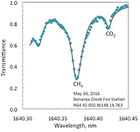
Figure 6. The retrieval algorithm is based on similar software that is currently used to analyze ground-based data. Shown here is a recent scan from the ground LHR of CO2 and CH4 above thawing permafrost in Alaska (May 2016). The primary difference is that transmission data will be taken from a horizontal atmospheric slice consisting primarily of the stratosphere, instead of vertically through all atmospheric layers.
Download figure:
Standard image High-resolution image
6. Conclusions
We have presented a compact (6 U) CubeSat design that implements a passive, sun-pointing LHR to observe CH4, CO2 and H2O in the limb at 1640 nm (6098 cm−1). The CubeSat design is based on a ground LHR instrument that measures CH4 and CO2 in the atmospheric column that has a current spectral resolution of ~3.6 pm (~0.013 cm−1) and a precision of 10 ppb for CH4 and 1 ppm for CO2 for 20 averaged scans. Space observations require precisions of ~0.5% for CH4 and 0.25% for CO2 and are achievable with this design based on the expected wavelength precision of ~3 × 10⁻⁶ nm (~10−5 cm−1) and better than 500:1 SNR. Water vapor precisions are expected to be ~1% and will contribute to CO2 and CH4 retrievals with respect to dry air in the same pathlengh. LHR measurements will fully resolve a single line of each greenhouse gas, including line shape and line width, for low-bias and high precision retrievals. This CubeSat will ideally be deployed into a LEO, high-inclination orbit where the ascending node is oriented 90° from the sun to produce the longest observations. Measurements of CH4, CO2, and H2O from the upper troposphere to the middle stratosphere will provide critical information on stratospheric circulation and how it responds to increasing greenhouse gas (GHG) concentrations.
Acknowledgments
Mini-LHR development was supported by the NASA Goddard Space Flight Center Internal Research and Development program and Science Innovation fund. This work was performed in part under the auspices of the US Department of Energy by Lawrence Livermore National Laboratory under Contract DE-AC52-07NA27344.
Footnotes
- 7
U is a CubeSat measurement designation defined as a volume of 10 cm3 and a mass of less than 1.33 kg. The 4 U instrument described here has dimensions of 20 cm × 20 cm × 10 cm.