
Abstract
Density functional theory (DFT) is nowadays one of the most broadly used and successful techniques to study the properties of polarons and their effects in materials. Here, we systematically analyze the aspects of the theoretical calculations that are crucial to obtain reliable predictions in agreement with the experimental observations. We focus on rutile TiO2, a prototypical polaronic compound, and compare the formation of polarons on the (110) surface and subsurface atomic layers. As expected, the parameter U used to correct the electronic correlation in the DFT + U formalism affects the resulting charge localization, local structural distortions and electronic properties of polarons. Moreover, the polaron localization can be driven to different sites by strain: due to different local environments, surface and subsurface polarons show different responses to the applied strain, with impact on the relative energy stability. An accurate description of the properties of polarons is key to understand their impact on complex phenomena and applications: as an example, we show the effects of lattice strain on the interaction between polarons and CO adsorbates.

Original content from this work may be used under the terms of the Creative Commons Attribution 4.0 licence. Any further distribution of this work must maintain attribution to the author(s) and the title of the work, journal citation and DOI.
1. Introduction
Excess charge in polarizable materials can couple to the lattice phonons and form polaron quasiparticles [1]. Since their formulation in the early twentieth century [2–5], polarons have extensively been studied in physics, materials science and chemistry [6–10], and continue nowadays to be of large interest due also to their impact on a wide range of modern technologies [11–16]. Titanium dioxide is a prototypical example for the study of polarons in materials [16–21]. In its rutile form, TiO2 is likely to host so-called small electron polarons, i.e., electrons strongly localized on one or few lattice sites, and associated to evident distortions of the local structure [22, 23]. The long series of diverse experiments performed on this compound [1, 21] has been accompanied by analysis at the density-functional theory (DFT) level, which is a broadly used technique for investigations of polaronic properties [24–39]. Modelization of the localized electrons requires a correction of the electronic correlation of the Ti d orbitals, that can be efficiently achieved by adopting the DFT + U technique: an additional energy term is introduced in the Hamiltonian, and tuned by a parameter U [40]. The value of U is typically determined by comparing the electronic properties of the simulated system with the experimental measurements, or by relying on different ab initio approaches [41–46].
Figure 1 collects general aspects of polaron formation on the rutile TiO2(110) surface as obtained by DFT + U calculations. Oxygen vacancies (VO) that easily develop on the surface of rutile samples introduce excess electrons into the system. Assuming a rigid band model, one would expect this excess charge to fill the bottom of the conduction band, with a transition from a semiconducting density of states (DOS), typical of the pristine surface (figure 1(b)), to a metallic phase (figure 1(c)): we refer to this system as delocalized solution, since the electronic states are spatially dispersed throughout the material (figure 1(e)). Formation of a polaronic state with the excess charge localized at single Ti atoms and associated to a sharp state in the energy gap (figures 1(a) and (d)) is predicted by DFT + U as a more stable solution. The charge localization can occur at different lattice sites, leading to polarons characterized by different properties and stability: usually, the most suitable hosting sites are the subsurface Ti atoms lying below the five-fold coordinated atoms (, see labeling in figure 1) [47–50]. However, environmental conditions and/or computational details can alter the polaron stability, and favor the charge localization elsewhere, especially on the surface atoms [26, 27, 43, 44, 51–55].


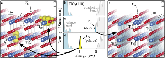
Figure 1. Excess electrons on rutile TiO2(110). DOS for a pristine slab (b), and a slab with one VO (oxygen vacancy concentration ) in the delocalized (c) and polaronic (d) solutions. Panels a and e show the spatial distribution of the charge density corresponding to the polaronic in-gap peak and to the electrons at the bottom of the conduction band, respectively (yellow and gray colors correspond to high and low isosurface levels).

Download figure:
Standard image High-resolution imageHere, we systematically analyze the polaronic properties of rutile TiO2(110), and the dependence on physical quantities, such as lattice strain, and the correction U of the electronic correlation in DFT + U calculations. In particular, we describe the change in the charge localization, local structural distortions and electronic properties of polarons as determined by different values of the U parameter. Moreover, we show that the application of strain along the [001] direction can reverse the stability of and polarons, in agreement with experimental observations, due to their different orbital symmetries and different interaction with the surrounding local structure. We emphasize that a precise knowledge of the effects of the parameters used in DFT calculations is key to obtain reliable predictions, in agreement with experiments: we conclude the manuscript by showing the effects of the altered relative stability of and polarons on a well studied application, the adsorption of CO molecules on the rutile surface [56].


2. Methods
This study was conducted in the framework of density functional theory (DFT), by using the Vienna ab initio simulation package (VASP) [57–59]. We adopted the generalized gradient approximation (GGA) with the Perdew, Burke, and Ernzerhof parametrization [60], optimized to account for Van-der-Waals dispersion interactions as originally proposed by Dion et al. (optPBE) [61, 62] in order to properly model the interaction with adsorbates. A correction for the electronic correlation was included by using an on-site effective U [40] of UcRPA = 3.9 eV on the d orbitals of the Ti atoms [63] (optPBE + U calculations), previously determined by constrained random-phase approximation (cRPA) calculations in bulk rutile [35]. The rutile surfaces were modeled with asymmetric slabs containing five Ti layers in large two-dimensional 9 × 2 and 6 × 2 unit cells, using low-temperature experimental lattice parameters [21], with the inclusion of a vacuum region of 15 Å. In our reference frame, the x, y and z Cartesian axis correspond to the [001], [10] and [110] crystallographic directions, respectively. All atomic sites except atoms on the bottom two layers were relaxed using standard convergence criteria with a plane-wave energy cutoff of 400 eV, and using the Γ point for sampling the reciprocal space.

Oxygen vacancies (VO) were included by removing one two-fold coordinated surface O atom from the 9 × 2 slabs, and one or two O atoms from the 6 × 2 slabs, corresponding to concentrations of 5.6%, 8.3%, and 16.7%, respectively. Every VO supplies two excess electrons, eligible to form two polarons [35]. We used VESTA [64] to show the spatial extension of the excess charge. The polaron formation energy EPOL () for sub-surface polarons distributed in equivalent localization sites in the slab is defined as the energy difference between the free energy of the system hosting polarons (Eloc) as compared to the energy of the system with the excess charge delocalized (Edel), divided by the number n of polarons in the slab: EPOL = (Eloc − Edel)/n. Single surface polarons were modeled by replacing one of the sub-surface polarons in the slab: the polaron formation energy EPOL () was calculated by further subtracting the EPOL () of the nS1 sub-surface polarons, EPOL () = Eloc − Edel − nS1 EPOL (). The results for EPOL () are comparable to the values obtained by modeling one single polaron and removing all remaining excess electron from the system, with the addition of a compensating background charge (results obtained in this setup are not shown here) [65]. The convergence of EPOL for the various polarons with respect to the modeling setup (number of atomic layers and lateral size of the slab) was discussed in previous works [65]. The CO adsorption energy (Eads) is calculated by subtracting from the energy of the system with the CO molecule adsorbing in a specific configuration i, the energy ES1 of the clean slab hosting two polarons in their optimal configuration and the energy of the CO molecule in the gas phase [54]: .


3. Results and discussion
Oxygen vacancies on the TiO2(110) surface cause the formation of polarons, as described in the Introduction and shown in figure 1. Typically, sub-surface ions are the most favorable sites for polaron localization, and they have been described in detail in the literature [16–21, 27–29, 35, 47–50, 52–55]. These polarons show a – orbital symmetry, with the polaronic charge extending on the plane of the equatorial oxygen atoms, and hybridizing with surrounding Ti atoms on the same plane.


We note that on the surface sites, polaron formation occurs instead with different characteristics. Figure 2 and table 1 report the different solutions as obtained for a polaron on the next nearest neighbor site from the VO. The dxz –dyz symmetry in figures 2(a) and (b) is the most stable solution (i.e., a dxz orbital, rotated from the [001] towards the direction of the bonds with two equatorial bonds), but the polaron can be stabilized also with the (figures 2(c) and (d)) and dyz (figures 2(e) and (f)) symmetries, with similar energy stability (ΔE = +25 and +40 meV with respect to the dxz –dyz solution, respectively). These different solutions can be spontaneously obtained by simply adopting different starting conditions in our DFT simulations, driving the system towards different minima of the energy configuration space. Polarons lying far from the vacancy, seem to adopt preferentially a dxz –dyz symmetry, while the nearest neighbor site to the vacancy allows for the stabilization of a symmetry, but these localization sites are in general less favorable than the site [50, 65].


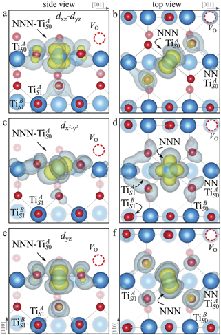
Figure 2. The polaron. Side (a), (c) and (e) and top (b), (d) and (f) views for three different orbital symmetries obtained for the polaron: dxz –dyz (a) and (b), (c) and (d) and dyz (e) and (f). Yellow and gray colors represent high and low isosurface levels for the polaronic charge density, respectively.


Download figure:
Standard image High-resolution imageTable 1. The polaron. Orbital characters and relative energy stability (ΔE) for the three different polarons (dxz –dyz , and dyz ).


| ΔE | dxy | dxz | dyz | |||
|---|---|---|---|---|---|---|
| dxz –dyz | 0 | — | 24 | 41 | — | — |
| +25 | — | 10 | 1 | 50 | 3 | |
| dyz | +40 | — | 6 | 58 | — | — |


The stabilization of a different orbital symmetry can be attributed to surface effects and to the structural buckling of the TiO2 surface structure: the tendency to stabilize the dxz –dyz symmetry is due to the misalignment between and atoms on the rutile surface that prevents the hybridization of the orbitals, typical for sub-surface polarons. However, surface oxygen vacancies perturb the local structure and partially suppress the buckling (see the distortions around the lattice defect in figures 1(a) and (e)): and atoms are practically aligned in the proximity of the VO, and this alignment stabilizes a orbital symmetry for a polaron on the or site, in analogy with the sub-surface polaron.


These different orbital symmetries can have different impact on the material properties: by considering for example the surface reactivity, the DFT calculations modeling the most favorable dxz –dyz symmetry well reproduce the ability of polarons to hybridize with CO adsorbates and form stable complexes on the surface sites [54]. These complexes are characterized by peculiar double-lobe signals in scanning tunneling microscopy (STM) measurements, well reproduced by DFT; conversely, the polaron in orbital symmetry interacts less favorably with the CO molecule, showing a weaker hybridization and less intense single-spot in the simulated STM, not supported by the experiments [65].


In the following, we focus on the dependence of the properties of the and the (dxz –dyz ) polarons on different quantities, including the electronic correlation and lattice strain, and further analyze the potential impact on applications.


3.1. The U parameter
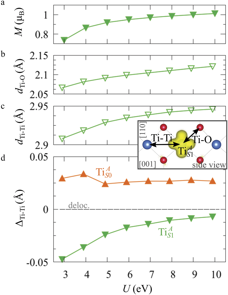
The properties of polarons depends strongly on the parameter U adopted in the DFT + U calculations to correct the electronic correlation. Figure 3 summarizes the effects of the U value on the localization of a polaron in terms of localized charge (evaluated by inspecting the local magnetization of the hosting site) and structural distortions. Larger U values determine a stronger localization of the polaronic charge: this is revealed by a magnetic moment progressively approaching a value of 1 μB (figure 3(a)). The variation in the charge localization is accompanied by a modification of the structural distortions around the polaronic sites: typically, anions (such as O atoms) around the polaron move away from localization sites as a result of the repulsive interactions with the excess electron, while cations (such as Ti atoms) are attracted by the electron polaron. Figures 3(b) and (c) show the evolution of the distance from a polaronic site of an octahedrally coordinated O atom (dTi–O) and the nearest Ti atom along [001] (dTi–Ti). As one might expect, the bond-length dTi–O increases for increasing U (figure 3(b)), due to the enhanced charge localization. Surprisingly, the attractive interaction with the nearest Ti atom is instead reduced by increasing U (dTi–Ti is shorter for smaller U values in figure 3(c)). This effect is shown also in figure 3(d), where we report the polaron-induced variation of the Ti–Ti distance (ΔTi–Ti) as compared to the Ti–Ti distance obtained in slabs with delocalized electrons: for large value of U, the polaronic distortion around the atom tends to the delocalized limit. This apparently counter-intuitive trend could be probably understood as a consequence of the displacement of the equatorial O oxygen atoms around the polaronic site, pushing the nearest Ti atoms away along the [001] direction.


Figure 3. Effects of U on the polaron localization. Magnetic moment (M) of the polaronic atom (a), bond-length distance dTi–O of an octahedrally coordinated O atom (b) and distance dTi–Ti of the nearest Ti along [001] (c) (as indicated in the inset). Panel (d) shows the polaronic distortion ΔTi–Ti, i.e., the variation of the Ti–Ti distance induced by the localization of a polaron with respect to the Ti–Ti distance as obtained in the delocalized solution (green down-pointing triangles and orange up-pointing triangles for the and polarons, respectively).


Download figure:
Standard image High-resolution imageThe (dxz –dyz ) polarons show similar trends for the charge localization and the distortions of the coordinated O atoms (not shown), but present a different behavior as far as the nearest Ti atoms are considered. As shown in figure 3(d), the nearest Ti atoms along [001] are found at larger distance than for a delocalized electron, at variance with the attractive regime of the polarons. (We considered the distance between the atom and the next site along [001], further away from the VO, in order to exclude contributions from the defect.) Moreover, the extent of this polaronic distortion seems to be not particularly affected by the U parameter. These diverse characteristics are due to the dxz –dyz orbital symmetry of the polaron: by modeling instead the surface polaron in the , a similar trend for the Ti–Ti distance as obtained for the polaron is retrieved (not shown).


Together with the polaron localization, the energy stability is highly affected by the value of U. Interestingly, polarons on different sites are affected to a different extent. Figure 4 compares the formation energy EPOL as a function of U for and polarons (typically, the most favorable sites for polarons formation on the rutile surface). By using the cRPA UcRPA value, polarons are more favorable (by approximately 100 meV) than polarons. By adopting smaller U values, the polarons become less stable and eventually delocalize (the polaron is destabilized already at U ≃ 3 while the polaron is slightly more resistant). On the other hand, large U values favor the formation of polarons: at approximately 1 eV above the UcRPA value (U ≃ 5 eV) formation of polarons becomes energetically less favorable than . The crossing takes place at even lower U values for strongly reduced slabs (e.g., U ≃ 4.5 eV for , not shown), closer to UcRPA. Considering that the stability of the S0 polarons is not typically supported by the experimental observations (on the clean surface, at low temperature), these large U values should be avoided in the calculations. Furthermore, the curves for both polarons show a kink at U ≃ 7 eV, with EPOL following a different linear trend at higher U values: this discontinuity can be understood by inspecting the corresponding electronic properties, as discussed below.


Figure 4. Effects of U on the polaron stability. Formation energy EPOL for the and polarons (in a slab with ), as a function of the effective U parameter.


Download figure:
Standard image High-resolution imageThe EPOL trend is associated to a modification of the polaronic in-gap state. Figure 5 shows the DOS obtained for the polaron. The position of the polaron state can be arbitrarily controlled by varying the U: upon variations of ±1 eV around UcRPA (up to approximately U = 5 eV), the polaron peak remains sharp and shifts within almost the whole energy gap. At higher U values, the polaronic state overlaps with the valence band, and, eventually, the d states of the hosting Ti site show no sharp features at U≳7 eV, in correspondence with the discontinuity observed for EPOL (figure 4).


Figure 5. Effects of U on the polaronic state. The total DOS (filled gray) and the projection on the polaronic atom (solid green line) are reported for various values of U (as indicated in every image).

Download figure:
Standard image High-resolution image3.2. Lattice strain
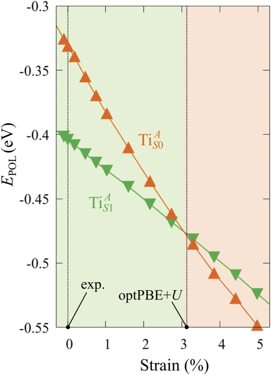
The stability of small polarons depends on the strain applied to the crystal [66]. Polarons localized on and sites are characterized by different local lattice distortions, as discussed in the previous section: while the bond-length with the coordinated O atoms are elongated by both polarons, the polaron tends to attract the nearest-neighbor Ti atoms, while the repels the nearest Ti atoms. We can describe this scenario by considering the polaron as subjected to a compressive stress, while the polaron experiences a tensile stress, as far as the surrounding Ti atoms are considered. This description suggests that these two inequivalent polarons could respond differently to strain. Figure 6 compares the effects of strain (applied along the [001] direction) on the energy stability EPOL for and polarons (with respect to the low-temperature experimental lattice constant c = 2.953 Å taken as reference, i.e., 0% strain [21]). As expected, a tensile strain along [001] enhances the stability of polarons to a larger extent as compared to the polaron. Ultimately, for very large values of the strain (≳3%), a phase transition occurs: the sites become the most favorable sites for polaron formation. Even though the atoms remain the most favorable hosting sites up to high amount of strain (%), some specific surface properties might get sensibly affected at smaller extent of strain, such as the surface reactivity (see discussion in the next section).


Figure 6. Effects of the lattice strain on the polaron stability. Formation energy EPOL for the and polarons (in a strongly reduced slab, ), as a function of the lattice strain along [001]. The dotted, vertical lines indicate the values for the [001] lattice vector as measured by the experiment and as obtained by slab relaxation at the optPBE + U level.


Download figure:
Standard image High-resolution imageWe conclude this section by underling the importance of the [001] lattice parameter used in the calculations to model the TiO2(110) surface. Due to the known tendency of GGA-based DFT + U calculations to overestimate the unit cell volume, our optimized [001] lattice parameter is about 3% larger than the experimental one, biasing the relative stability between non-equivalent polarons. By using the low-temperature experimental parameters to model the system instead of relying on the calculated lattice, the results on the polaronic properties appear more reasonably in agreement with the experimental observation.
We note also that the calculated lattice parameter depends on the reduction level of the slab: larger concentrations of oxygen vacancies show a stronger elongation of the [001] vector (3.1% for ) as compared to the pristine surface (3.0%). This effect is probably due to the broken bonds on the surface at the VO sites, and might explain the tendency of rutile sample to exhibit polarons at highly reducing conditions [51, 54]: the elongation along [001] mitigates the compressive stress on the polaron, resulting in a stronger stability.


3.3. CO adsorption
Polarons play a decisive role for the surface reactivity of rutile TiO2(110). The adsorption of CO molecules has been a well studied testbed case that has contributed to clarify the role of polarons in reaction processes [54, 67–74]. At low coverage, CO molecules adsorb in a vertical orientation on the TiO2(110) surface. Adsorption on VO sites is typically very favorable and not influenced by polarons. CO adsorption on the five fold coordinated is instead driven by the polarons: at low CO coverage and highly reducing conditions, the molecules preferably adsorb at sites, due to the coupling with -polarons, as recently reported by scanning probe experiments [54]. Weakly reduced samples exhibit few CO+-polaron complexes together with CO molecules adsorbing on sites at large distance from the VO and from the polarons ( CO), showing no significant electronic coupling with the polaronic states.


Figure 7 shows the effects of strain on the properties of CO adsorption, as predicted by DFT calculations for a weakly reduced slab ( = 5.6%). As far as the low-temperature [001] lattice parameter is used in the simulations (0% of strain), DFT well describes the coexistence of CO+-polaron complexes with CO molecules (see the comparable Eads values at 0% strain in figure 7) [54]. However, even modest tensile strain along [001] favors the polaron hopping towards the surface, and the CO+-polaron complexes become dominant. Conversely, by applying strong compressive strain (≃−1%), the calculations predict a splitting of the CO+-polaron complex, in favor of a polaron lying on a site below the CO molecule in the proximity of the VO (labeled as CO@ in the figure) in addition to the CO configuration.


Figure 7. Tuning the adsorption process by applied strain. Adsorption energy Eads for a CO molecule adsorbing at low reducing conditions , as a function of lattice strain applied along [001]. Three different adsorption configurations are considered: CO molecule adsorbing in the proximity of the VO and coupling with a polarons (orange, up-pointing triangles); CO molecule adsorbing in the proximity of the VO above a sub-surface polaron (CO@, green, empty, down-pointing triangles); CO molecule adsorbing on a Ti site far from both the VO and any polaron ( CO, green, filled, down-pointing triangles). The inset sketches the top view of the rutile surface, with the polaron localization and CO adsorption sites indicated by the labels (surface Ti atoms in orange circles, subsurface Ti atoms in smaller green circles).


Download figure:
Standard image High-resolution imageBeside providing useful ways of controlling adsorption and catalysis processes, strain effects clearly indicate that calculations performed using the DFT + U-optimized lattice constant overestimate unrealistically the stability of CO+-polaron complex, against experimental observation. It is clear that comparison with experiment and accurate control over the polaron properties is crucial to obtain reasonable predictions.

4. Summary and conclusions
In summary, we reported a systematic DFT analysis on the properties of polarons on rutile TiO2(110), focusing on the effects of lattice strain and computational details. The U parameter used in the calculation for correcting the electronic correlation on transition metals shows a broad impact, influencing the charge localization, the local lattice distortions and the electronic state of the polarons. Different types of polarons are affected to a different extent by the U value, and phase transitions could be artificially driven in the calculations depending on the adopted parameter: the sub-surface polarons typically reported by the experiments are predicted as the most stable type for U values ranging ±1 eV around the UcRPA = 3.9 eV value calculated by cRPA simulations in the bulk. Moreover, charge trapping can be driven to different lattice sites upon applied strain: this suggests a possible mechanism for controlling the polaron localization, in addition to underline the importance of a careful parametrization in the calculations. The modeling of the excess electrons is indeed a delicate task, due to a potential energy surface characterized by numerous local minima [75], determined by the various possible polaron arrangements and the different electronic properties of these electronic states. The benchmark with experiments is of fundamental importance in order to obtain reliable predictions [76, 77] and to accurately describe complex phenomena influenced by polarons [1].
Additionally, we showed how the functionalities of polaronic materials can be tuned by controlling the polaron properties. We focused on the adsorption of CO molecules: CO adsorbates can be driven to different adsorption sites upon application of strain, arbitrarily favoring or disfavoring the coupling with surface polarons. Control over the adsorption process and the electronic properties of the adsorbates represent an interesting and coveted feature that could be exploited for applications in the field of catalysis.
Finally, we note that the development of efficient functional oxide materials requires an accurate atomic-scale understanding of the effects brought about by oxidation and reduction reactions. Our study highlights the importance of a precise modeling of reducible oxides and the need to account for different arrangement and types of polarons, which can be achieved by extensive exploration of the polaronic configuration space [27, 35, 51, 78, 79].
Acknowledgments
This work was funded by the Austrian Science Fund (FWF) project F81, SFB 'TACO'.
Data availability statement
The data that support the findings of this study are available upon reasonable request from the authors.