

Abstract
Wannier90 is an open-source computer program for calculating maximally-localised Wannier functions (MLWFs) from a set of Bloch states. It is interfaced to many widely used electronic-structure codes thanks to its independence from the basis sets representing these Bloch states. In the past few years the development of Wannier90 has transitioned to a community-driven model; this has resulted in a number of new developments that have been recently released in Wannier90 v3.0. In this article we describe these new functionalities, that include the implementation of new features for wannierisation and disentanglement (symmetry-adapted Wannier functions, selectively-localised Wannier functions, selected columns of the density matrix) and the ability to calculate new properties (shift currents and Berry-curvature dipole, and a new interface to many-body perturbation theory); performance improvements, including parallelisation of the core code; enhancements in functionality (support for spinor-valued Wannier functions, more accurate methods to interpolate quantities in the Brillouin zone); improved usability (improved plotting routines, integration with high-throughput automation frameworks), as well as the implementation of modern software engineering practices (unit testing, continuous integration, and automatic source-code documentation). These new features, capabilities, and code development model aim to further sustain and expand the community uptake and range of applicability, that nowadays spans complex and accurate dielectric, electronic, magnetic, optical, topological and transport properties of materials.
Export citation and abstract BibTeX RIS

Original content from this work may be used under the terms of the Creative Commons Attribution 3.0 licence. Any further distribution of this work must maintain attribution to the author(s) and the title of the work, journal citation and DOI.
1. Introduction
Wannier90 is an open-source code for generating Wannier functions (WFs), in particular maximally-localised Wannier functions (MLWFs), and using them to compute advanced materials properties with high efficiency and accuracy. Wannier90 is a paradigmatic example of interoperable software, achieved by ensuring that all the quantities required as input are entirely independent of the underlying electronic-structure code from which they are obtained. Most of the major and widely used electronic-structure codes have an interface to Wannier90, including Quantum ESPRESSO [1], ABINIT [2], VASP [3–5], Siesta [6], Wien2k [7], Fleur [8], Octopus [9] and ELK [10]. As a consequence, once a property is implemented within Wannier90, it can be immediately available to users of all codes that interface to it.
Over the last few years, Wannier90 has undergone a transition from a code developed by a small group of developers to a community code with a much wider developer base. This has been achieved in two principal ways: (i) hosting the source code and associated development efforts on a public GitHub repository [11]; and (ii) building a community of Wannier90 developers and facilitating personal interactions between individuals through community workshops, the most recent in 2016. In response, the code has grown significantly, gaining many novel features contributed by this community, as well as numerous fixes.
In this paper, we describe the most important novel contributions to the Wannier90 code, as embodied in its 3.0 release. The paper is structured as follows: in section 2 we first summarise the background theory for the computation of MLWFs (additional details can be found in [12]), and introduce the notation that will be used throughout the paper. In section 3 we describe the novel features of Wannier90 that are related to the core wannierisation and disentanglement algorithms; these include symmetry-adapted WFs, selective localisation of WFs, and parallelisation using the message-passing interface (MPI). In section 4 we describe new functionality enhancements, including the ability to handle spinor-valued WFs and calculations with non-collinear spin that use ultrasoft pseudopotentials (within Quantum ESPRESSO); improved interpolation of the k-space Hamiltonian; a more flexible approach for handling and using initial projections; and the ability to plot WFs in Gaussian cube format on WF-centred grids with non-orthogonal translation vectors. In section 5 we describe new functionalities associated with using MLWFs for computing advanced electronic-structure properties, including the calculation of shift currents, gyrotropic effects and spin Hall conductivities, as well as parallelisation improvements and the interpolation of bands originating from calculations performed with many-body perturbation theory (GW). In section 6 we describe the selected-columns-of-the-density-matrix (SCDM) method, which enables computation of WFs without the need for explicitly defining initial projections. In section 7 we describe new post-processing tools and codes, and the integration of Wannier90 with high-throughput automation and workflow management tools (specifically, the AiiDA materials' informatics infrastructure [13]). In section 8 we describe the modern software engineering practices now adopted in Wannier90, that have made it possible to improve the development lifecycle and transform Wannier90 into a community-driven code. Finally, our conclusions and outlook are presented in section 9.
2. Background
WFs form a possible basis set for the electronic states of materials. As we are going to describe in the following, WFs are not unique and they can be optimised to obtain MLWFs. These are particularly useful in a number of electronic-structure applications. For instance, they enable efficient interpolation of operator matrix elements on dense grids in the Brillouin Zone (BZ), which is a key step to compute many materials properties. The interpolation is obtained starting from the value of these matrix elements and other properties of the wavefunctions (described below) computed on a coarser grid, usually with an accurate but slower ab initio code. MLWFs play in materials a role analogous to molecular orbitals in molecules and some typical MLWFs, e.g., in the case of those corresponding to the valence bands of GaAs, are discussed in section 3.3.
Formally, MLWFs can be introduced as follows in the independent-particle approximation. The electronic structure of a periodic system is conventionally represented in terms of one-electron Bloch states  , which are labelled by a band index n and a crystal momentum
  inside the first BZ, and which satisfy Bloch's theorem:

where  is a periodic function with the same periodicity of the single-particle Hamiltonian, and
  is a Bravais lattice vector. For the moment we ignore the spin degrees of freedom and work with spinless wave functions; spinor wave functions will be treated in section 4.1. Such a formalism is also commonly applied, via the supercell approximation, to non-periodic systems, typically used to treat point, line and planar defects in crystals, surfaces, amorphous solids, liquids and molecules.
2.1. Isolated bands
A group of bands is said to be isolated if it is separated by energy gaps from all the other lower and higher bands throughout the BZ (this isolated group of bands may still show arbitrary crossing degeneracies and hybridisations within itself). For a set of J such bands, the electronic states can be equivalently represented by a set of J WFs per cell, that are related to the Bloch states via two unitary transformations (one continuous, one discrete) [14]:

where  is a periodic (but not necessarily localised) WF labelled by the quantum number
  (the conjugate variable of the quasi-momentum
  in the Bloch representation),
  is the cell volume and
  are unitary matrices that mix Bloch states at a given
  and represent the gauge freedom that exists in the definition of the Bloch states and that is inherited by the WFs.
MLWFs are obtained by choosing  matrices that minimise the sum of the quadratic spreads of the WFs about their centres for a reference
  (say,
(say,  ). This sum is given by the spread functional

 may be decomposed into two positive-definite parts [15],

where

is gauge invariant (i.e. invariant under the action of any unitary  on the Bloch states), and

is gauge dependent. Therefore, the "wannierisation" of an isolated manifold of bands, i.e. the transformation of Bloch states into MLWFs, amounts to minimising the gauge-dependent part  of the spread functional.
Crucially, the matrix elements of the position operator between WFs can be expressed in reciprocal space. Under the assumption that the BZ is sampled on a uniform Monkhorst–Pack mesh of k-points composed of N points ( ), the gauge-independent and gauge-dependent parts of the spread may be expressed, respectively, as [15]

and

where  are the vectors connecting a k-point to its neighbours, wb are weights associated with the finite-difference representation of
  for a given geometry, the matrix of overlaps
  is defined by

and the centres of the WFs are given by

Minimisation of the spread functional is achieved by considering infinitesimal gauge transformations  , where
  is anti-Hermitian (
 ). The gradient of the spread functional with respect to such variations is given by

where  and
and  are the super-operators
 ![$ \newcommand{\re}{{\rm Re}} \renewcommand{\dag}{\dagger}\mathcal{A}[B]=(B-B^\dagger)/2$](https://content.cld.iop.org/journals/0953-8984/32/16/165902/revision2/cmab51ffieqn033.gif) and
and ![$ \newcommand{\re}{{\rm Re}} \renewcommand{\dag}{\dagger}\mathcal{S}[B]=(B+B^\dagger)/2{\rm i}$](https://content.cld.iop.org/journals/0953-8984/32/16/165902/revision2/cmab51ffieqn034.gif) , respectively, and
, respectively, and


For the full derivation of equation (11) we refer to [15]. This gradient is then used to generate a search direction  for an iterative steepest-descent or conjugate-gradient minimisation of the spread [16]: at each iteration the unitary matrices are updated according to

where  is a coefficient that can either be set to a fixed value or determined at each iteration via a simple polynomial line-search, and the matrix exponential is computed in the diagonal representation of
  and then transformed back in the original representation. Once the unitary matrices have been updated, the updated set of
  matrices is calculated according to

where

is the set of initial  matrices, computed once and for all, at the start of the calculation, from the original set of reference Bloch orbitals
 ![$ \renewcommand{\ket}[1]{|#1\rangle} \ket{u^{(0)}_{n{\bf k}}}$](https://content.cld.iop.org/journals/0953-8984/32/16/165902/revision2/cmab51ffieqn040.gif) .
.
2.2. Entangled bands
It is often the case that the bands of interest are not separated from other bands in the Brillouin zone by energy gaps and overlap and hybridise with other bands that extend beyond the energy range of interest. In such cases, we refer to the bands as being entangled.
The difficulty in constructing MLWFs for entangled bands arises from the fact that, within a given energy window, the number of bands  at each k-point
  in the BZ is not a constant and is, in general, different from the target number J of WFs:
  . Even making the energy window k-dependent would see discontinuous inclusion and exclusion of bands as the BZ is traversed. The treatment of entangled bands requires thus a more complex approach that is typically a two-step process. In the first step, a J-dimensional manifold of Bloch states is selected at each k-point, chosen to be as smooth as possible as a function of
  . In the second step, the gauge freedom associated with the selected manifold is used to obtain MLWFs, just as described in section 2.1 for the case of an isolated set of bands.
Focusing on the first step, an orthonormal basis for the J-dimensional subspace  at each
  can be obtained by performing a semi-unitary transformation on the
  states at
  ,
,

where  is a rectangular matrix of dimension
  that is semi-unitary in the sense that
  .
.
To select the smoothest possible manifold, a measure of the intrinsic smoothness of the chosen subspace is needed. It turns out that such a measure is given precisely by the gauge-invariant part  of the spread functional for isolated bands [17]. Indeed, equation (7) can be expressed as

where ![$ \renewcommand{\Bra}[1]{\langle#1|} \newcommand{\Ketbra}[2]{\Ket{#1}\Bra{#2}} \renewcommand{\Ket}[1]{|#1\rangle} {P}_{{\bf k}}=\sum\nolimits_{n=1}^{J}\Ketbra{\widetilde{u}_{n{\bf k}}}{\widetilde{u}_{n{\bf k}}}$](https://content.cld.iop.org/journals/0953-8984/32/16/165902/revision2/cmab51ffieqn053.gif) is the projection operator onto
is the projection operator onto  ,
,  is its Hilbert-space complement, and '
 ' represents the trace over the entire Hilbert space.
 ![$ \newcommand{\Trace}{\mathrm{Tr}} \newcommand{\Tr}{{\rm Tr}}\Trace [{P}_{{\bf k}}{Q}_{{\bf k}+{\bf b}}]$](https://content.cld.iop.org/journals/0953-8984/32/16/165902/revision2/cmab51ffieqn057.gif) measures the mismatch between the subspaces
measures the mismatch between the subspaces  and
and  , vanishing if they overlap identically. Hence
  measures the average mismatch of the local subspace
  across the BZ, so that an optimally-smooth subspace can be selected by minimising
  . Doing this with orthonormality constraints on the Bloch-like states is equivalent to solving self-consistently the set of coupled eigenvalue equations [17]

The solution can be achieved via an iterative procedure, whereby at the i iteration the algorithm traverses the entire set of k-points, selecting at each one the J-dimensional subspace
  that has the smallest mismatch with the subspaces
  at the neighbouring k-points obtained in the previous iteration. This amounts to solving

and selecting the J eigenvectors with the largest eigenvalues [17]. Self-consistency is reached when  (to within a user-defined threshold) at all the k-points. To make the algorithm more robust, the projector appearing on the left-hand-side of equation (21) is replaced with
 ![$[{P}_{{\bf k}+{\bf b}}^{(i)}]_{\mathrm{in}}$](https://content.cld.iop.org/journals/0953-8984/32/16/165902/revision2/cmab51ffieqn067.gif) , given by
, given by

which is a linear mixture of the projector that was used as input for the previous iteration and the projector defined by the output of the previous iteration. The parameter  determines the degree of mixing, and is typically set to
  ; setting
  reverts precisely to equation (21), while smaller and smaller values of
  make convergence smoother (and thus more robust) but also slower.
In practice, equation (21) is solved by diagonalising the Hermitian operator appearing on the left-hand-side in the basis of the original  Bloch states:

Once the optimal subspace has been selected, the wannierisation procedure described in section 2.1 is carried out to minimise the gauge-dependent part  of the spread functional within that optimal subspace.
2.3. Initial projections
In principle, the overlap matrix elements  are the only quantities required to compute and minimise the spread functional, and generate MLWFs for either isolated or entangled bands. In practice, this is generally true when dealing with an isolated set of bands, but in the case of entangled bands a good initial guess for the subspaces
  alleviates problems associated with falling into local minima of
  , and/or obtaining MLWFs that cannot be chosen to be real-valued (when no spin-orbit coupling is included). Even in the case of an isolated set of bands, a good initial guess for the WFs, whilst not usually critical, often results in faster convergence of the spread to the global minimum. (It is important to note that both for isolated and for entangled bands multiple solutions to the wannierisation or disentanglement can exist, as discussed later.)
A simple and effective procedure for selecting an initial gauge (in the case of isolated bands) or an initial subspace and initial gauge (in the case of entangled bands) is to project a set of J trial orbitals  localised in real space onto the space spanned by the set of original Bloch states at each
  :
:

where the sum runs up to either J or  , depending on whether the bands are isolated or entangled, respectively, and the inner product
 ![$ \renewcommand{\Bra}[1]{\langle#1|} \renewcommand{\Braket}[1]{\langle#1\rangle} \newcommand{\inprod}[2]{\Braket{#1 | #2}} \newcommand{\amn}{A_{mn\mathbf{k}}} \amn=\inprod{\psi_{m{\bf k}}}{g_n}$](https://content.cld.iop.org/journals/0953-8984/32/16/165902/revision2/cmab51ffieqn080.gif) is over the Born–von Karman supercell. (In practice, the fact that the gn are localised greatly simplifies this calculation.) The matrices
is over the Born–von Karman supercell. (In practice, the fact that the gn are localised greatly simplifies this calculation.) The matrices  are square
  or rectangular
  in the case of isolated or entangled bands, respectively. The resulting orbitals are then orthonormalised via a Löwdin transformation [18]:


where ![$ \renewcommand{\Bra}[1]{\langle#1|} \renewcommand{\Braket}[1]{\langle#1\rangle} \newcommand{\inprod}[2]{\Braket{#1 | #2}} \newcommand{\smn}{S_{mn\mathbf{k}}} \newcommand{\re}{{\rm Re}} \renewcommand{\dag}{\dagger}\smn={\inprod{\phi_{m{\bf k}}}{\phi_{n{\bf k}}}}=(A_{{\bf k}}^{\dagger}A_{{\bf k}}^{\phantom{\dagger}})_{mn}$](https://content.cld.iop.org/journals/0953-8984/32/16/165902/revision2/cmab51ffieqn084.gif) , and
, and  is a unitary matrix in the case of isolated bands and semi-unitary in the case of entangled bands. In the case of entangled bands, once an optimally-smooth subspace has been obtained as described in section 2.2, the same trial orbitals
  can be used to initialise the wannierisation procedure of section 2.1. In practice, the matrices
  are computed once and for all at the start of the calculation, together with the overlap matrices
  . These two operations need to be performed within the context of the electronic-structure code and basis set adopted; afterwards, all the operations of Wannier90 rely only on
  and
and  and not on the specific representation of
  (e.g. plane waves, linearised augmented plane waves, localised basis sets, real-space grids, ...).
3. New features for wannierisation and disentanglement
In this section we provide an overview of the new features associated with the core wannierisation and disentanglement algorithms in Wannier90, namely the ability to generate WFs of specific symmetry; selectively localise a subset of the WFs and/or constrain their centres to specific sites; and perform wannierisation and disentanglement more efficiently through parallelisation.
3.1. Symmetry-adapted Wannier functions
In periodic systems, atoms are usually found at sites  whose site-symmetry group Gq is a subgroup of the full point group F of the crystal [19] (the symmetry operations in the group Gq are those that leave
  fixed). The set of points
  that are symmetry-equivalent sites to
  is called an orbit [20]. These are all the points in the unit cell that can be generated from
  by applying the symmetry operations in the full space group G that do not leave
  fixed. If
  is a high-symmetry site then its Wyckoff position has a single orbit [20]; for low-symmetry sites different orbits correspond to the same Wyckoff position. The number of points in the orbit(s) is the multiplicity
  of the Wyckoff position.
  , however, are not bound to reside on such high-symmetry sites, and they do not necessarily possess the site symmetries of the crystal [17, 21, 22]. When using
  as a local orbital basis set in methods such as first-principles tight binding, DFT + U and DFT plus dynamical-mean-field theory (DMFT), which deal with beyond-DFT correlations in a local subspace such as that spanned by d orbitals (e.g. for systems containing transition metals atoms) or f orbitals (e.g. for systems containing rare-earth or actinide series atoms), it is often desirable to ensure that the WFs basis possesses the local site symmetries.
Sakuma [21] has shown that such symmetry-adapted Wannier functions (SAWFs) can be constructed by introducing additional constraints on the unitary matrices  of equation (2) during the minimisation of the spread. SAWFs, therefore, can be fully integrated within the original maximal-localisation procedure. The SAWF approach gives the user a certain degree of control over the symmetry and centres of the Wannier functions at the expense of some localisation since the final total spread of the resulting SAWFs can only be equal to, or most often larger than, that of the corresponding
  with no constraints (note that in principle some SAWFs can have a smaller individual spread than any
  ).
).
For a given point  in the home unit cell
  , the SAWFs centred at that point are denoted by

where  is the character of the irreducible representation (irrep) of the corresponding site-symmetry group Ga with dimension
  . For instance, in a simple fcc crystal such as copper (Cu), the site-symmetry group associated with the Cu site is Oh; one of its irreps [20] is e.g. 3-dimensional T2g and, assuming the Cu atom is located at the origin
  of the unit cell, three associated SAWFs are denoted
  and
and  .
.
To find these SAWFs, one needs to specify appropriate unitary transformations  of the Bloch states, defined by

where  are basis functions of the irrep
  and are formed from linear combinations of the J eigenstates
  of the Hamiltonian H. Since H is invariant under the full space group G, the representation of a given symmetry operation
  (where
  and
and  are the rotation and fractional-translation parts of the symmetry operation, respectively) in the basis
  must be a
  unitary matrix [19]
  , i.e.
  represents how the J Bloch states are transformed by the symmetry operation g:

where the matrix elements  are given by

On the other hand, the Bloch functions  , defined in equation (28), transform under the action of
  as
as

where  is the matrix representation of the symmetry operation g in the basis of
  ; the reader is referred to [19, 21] for details.
From equations (28), (29) and (31), it can be shown [21] that, for a symmetry operation  that leaves a given
  unchanged, the following relationship holds:

and, to obtain SAWFs, the initial unitary matrix  (
( IBZ) must satisfy this constraint. This can be achieved iteratively, starting with the initial projection onto localised orbitals as described in section 2.3, and with knowledge of
  (equation (29)) and
  (equation (31)), as discussed in detail in [21]. The matrices
  , which are independent of the underlying basis-set used to represent the Bloch states and are computed only once at the start of the calculation, can be calculated directly from the Bloch states via equation (30). The matrices
  are calculated by specifying the centre
  and the desired symmetry of the Wannier functions (e.g. s, p , d etc) and, for each symmetry operation ga in the site-symmetry group Ga, calculating the matrix representation of the rotational part.
For an isolated set of bands, the minimisation of  with the constraints defined in equation (32) requires the gradient
 ![$ \newcommand{\tinysup}[1]{^{{{\rm #1}}}} \mathcal{G}\tinysup{sym}_{{\bf k}}$](https://content.cld.iop.org/journals/0953-8984/32/16/165902/revision2/cmab51ffieqn138.gif) of the total spread
of the total spread  with respect to a symmetry-adapted gauge variation, which is then used to generate a search direction
 ![$ \newcommand{\tinysup}[1]{^{{{\rm #1}}}} \mathcal{D}\tinysup{sym}_{{\bf k}}$](https://content.cld.iop.org/journals/0953-8984/32/16/165902/revision2/cmab51ffieqn140.gif) . The symmetry-adapted gradient is given by
. The symmetry-adapted gradient is given by

where  is the original gradient given in equation (11), and
  is the number of symmetry operations in G that leave
  fixed. It is worth noting that there is no guarantee that equation (32) can be satisfied for any irrep, for example, when one is considering a target energy window with a limited number of Bloch states whose symmetry might not be compatible with the irrep.
In the case of entangled bands, a similar two-step approach is taken as in the case of MLWFs (section 2.2): first  is minimised by selecting an optimal subspace of Bloch states that are required to transform according to equation (31), followed by minimisation of
  with respect to gauge variations that respect the site symmetries within this subspace, as described for the case of isolated bands above, but with the difference that the constraint of equation (32) is modified to

since the states of the optimal subspace transform according to equation (31), rather than equation (29).
An implementation of the SAWF algorithm for both isolated and entangled bands can be found in pw2wannier90, the interface code between Quantum ESPRESSO and Wannier90. A typical calculation consists of the following steps: (a) define the symmetry operations of the site-symmetry group. These are either calculated by ![$ \newcommand{\exec}[1]{{\tt #1.x}} \newcommand{\e}{{\rm e}} \newcommand{\pwtowan}{{\exec{pw2wannier90}}} \pwtowan$](https://content.cld.iop.org/journals/0953-8984/32/16/165902/revision2/cmab51ffieqn146.gif) , if the site-symmetry group is equivalent to the full space group of the crystal, or they can be provided in the .sym file (e.g. if the site-symmetry group contains fewer symmetry operations than the full space group). (b) Specify the site location and orbital symmetry of the SAWFs. These are defined in the projection block of the Wannier90 input file .win file. (c) Run a preprocessing Wannier90 calculation to write this information into an intermediate file (with extension .nnkp) which is then read by
, if the site-symmetry group is equivalent to the full space group of the crystal, or they can be provided in the .sym file (e.g. if the site-symmetry group contains fewer symmetry operations than the full space group). (b) Specify the site location and orbital symmetry of the SAWFs. These are defined in the projection block of the Wannier90 input file .win file. (c) Run a preprocessing Wannier90 calculation to write this information into an intermediate file (with extension .nnkp) which is then read by ![$ \newcommand{\exec}[1]{{\tt #1.x}} \newcommand{\e}{{\rm e}} \newcommand{\pwtowan}{{\exec{pw2wannier90}}} \pwtowan$](https://content.cld.iop.org/journals/0953-8984/32/16/165902/revision2/cmab51ffieqn147.gif) . (d) Run
. (d) Run ![$ \newcommand{\exec}[1]{{\tt #1.x}} \newcommand{\e}{{\rm e}} \newcommand{\pwtowan}{{\exec{pw2wannier90}}} \pwtowan$](https://content.cld.iop.org/journals/0953-8984/32/16/165902/revision2/cmab51ffieqn148.gif) to calculate the
to calculate the  matrix in equation (31).
 ![$ \newcommand{\exec}[1]{{\tt #1.x}} \newcommand{\e}{{\rm e}} \newcommand{\pwtowan}{{\exec{pw2wannier90}}} \pwtowan$](https://content.cld.iop.org/journals/0953-8984/32/16/165902/revision2/cmab51ffieqn150.gif) computes also the
computes also the  matrix in equation (30) from the Kohn–Sham states of the DFT calculation. (e) These matrices are then written to a .dmn file which is read by Wannier90 at the start of the optimisation.
3.2. Selectively-localised Wannier functions and constrained Wannier centres
Wang et al have proposed an alternative method [23] to the symmetry-adapted Wannier functions described in section 3.1. Their method permits the selective localisation of a subset of the Wannier functions, which may optionally be constrained to have specified centres. Whilst this method does not enforce or guarantee symmetry constraints, it has been observed in the cases that have been studied [23] that Wannier functions whose centres are constrained to a specific site typically possess the corresponding site symmetries.
For an isolated set of J bands, selective localisation of a subset of  Wannier functions is accomplished by minimising the total spread
  with respect to only
  degrees of freedom in the unitary matrix
  . The spread functional to minimise is then given by

which reduces to the original spread functional  of equation (3) for
  . When
  , it is no longer possible to cast the functional
  as a sum of a gauge-independent term
  and gauge-dependent one
  , as done in equation (4) for
  . Nevertheless, the minimisation can be carried out with methods very similar to those described in section 2. In fact, for
  ,
,  can be written as the sum of two gauge-dependent terms,
  , where
  is formally given by the sum of
  and the off-diagonal term
  of
of  , and
, and  by the diagonal term
  of
of  . If one adopts the usual discrete representation on a uniform Monkhorst–Pack grid of k-points,
  and
and  are given by [23]

and

With this new spread functional, we can mimic the procedure used to obtain a set of  , and derive the gradient
  of
of  which gives the search direction to be used in the minimisation. The matrix elements of
  read
read

where  are the matrix elements of the original gradient in equation (11) (see also [15]), and
  and
and  are given by equations (12) and (13), respectively. As a result of the minimisation, we obtain a set of
  maximally-localised Wannier functions, known as selectively-localised Wannier functions (SLWFs), whose spreads are in general smaller than the corresponding
  . Naturally, the remaining
  functions will be more delocalised than their
  counterparts, as they are not optimised, and the overall sum of spreads will be larger (or in the best case scenario equal).
The centres of the  may be constrained by adding a quadratic penalty function to the spread functional
  , defining a new functional given by

where  is a Lagrange multiplier and
  is the desired centre for the n
 WF. The procedure outlined above for minimising
  can be also adapted to deal with
  (see [23] for details), and minimising
  results in selectively-localised Wannier functions subject to the constraint of fixed centres (SLWF + C). As noted above, it is observed that WFs derived using the SLWF + C approach naturally possess site symmetries, and their individual spreads are usually smaller than the corresponding spreads of
  , although the total spread, combination of the
  selectively optimised WFs and the
  unoptimised functions, is larger than the total spread of the
  (see, for instance last column of the table in figure 1).

Figure 1. Top (figure): comparison of two representative Wannier functions resulting from different minimisation schemes for gallium arsenide (larger pink spheres: Ga cation atoms, smaller yellow spheres: As anions): (a), (e) MLWF; (b), (f) SAWF; (c), (g) SLWF; (d), (h) SLWF + C. For MLWF, SLWF and SLWF + C, four s-type orbitals centred at the midpoints of the four Ga–As bonds are used as the initial guess. In the case of SLWF and SLWF + C, we optimise the first WF (and also constrain its centre to sit at ( ), i.e. on the As atom, for SLWF + C), while all the other WFs are left unoptimised. For SAWF, one s-type and three p -type orbitals centred on the As atom are used as initial guess. Specifically, the first row shows one MLWF (a), one SAWF with s character centred on As (b), one WF obtained with the selective localisation scheme (c) and one WF obtained obtained with the selective localisation scheme with additional constraints on its centre (d). The second row shows one of the other three WFs for all four methods. In particular: (e) MLWF, (f) SAWF with p character, (g) unoptimised SAWF and (f) unoptimised SAWF + C. For all plots we choose an isosurface level of
  0.5
0.5 
 (blue for + values and red for − values) using the Vesta visualisation program [28]. Bottom (table): Cartesian coordinates of the centres
 ![$ \newcommand{\overbar}[1]{\mkern1.5mu\overline{\mkern-1.5mu#1\mkern-1.5mu}\mkern 1.5mu} \overbar{{\bf r}}$](https://content.cld.iop.org/journals/0953-8984/32/16/165902/revision2/cmab51ffieqn005.gif) and minimised individual spreads
and minimised individual spreads ![$ \newcommand{\overbar}[1]{\mkern1.5mu\overline{\mkern-1.5mu#1\mkern-1.5mu}\mkern 1.5mu} \renewcommand{\bra}[1]{\langle#1|} \renewcommand{\braket}[1]{\langle#1\rangle} \braket{r^2}-\overbar{r}^2$](https://content.cld.iop.org/journals/0953-8984/32/16/165902/revision2/cmab51ffieqn006.gif) for the two representative Wannier functions of each of the four different minimisation schemes and initial guesses described above. We also report the total spread
for the two representative Wannier functions of each of the four different minimisation schemes and initial guesses described above. We also report the total spread  of all four valence WFs for each method.
Download figure:
Standard image High-resolution imageIn the case of entangled bands, the SLWF(+C) method implicitly assumes that a subspace selection has been performed, i.e. that a smooth J-dimensional manifold exists. Since for the  and
and  functionals it is not possible to define an
  that measures the intrinsic smoothness of the underlying manifold, the additional constraints in equations (35) and (39) can only be imposed during the wannierisation step. This means that SLWF(+C) can be seamlessly coupled with the disentanglement procedure, with no further additions to the original procedure of section 2.2.
3.3. SAWF and SLWF + C in GaAs
As an example of the capabilities of the SAWF and SLWF + C approaches, we show how to construct atom-centred WFs that possess the local site symmetries in gallium arsenide (GaAs). In particular, we discuss how to obtain one WF from the four valence bands of GaAs that is centred on the As atom and that transforms like the identity under the symmetry operations in Td, the site-symmetry group of the As site (for completeness, we also show one  and one SLWF without constraints). Since we only deal with the four valence bands of GaAs—an isolated manifold—no prior subspace selection is required for the wannierisation. All calculations were carried out with the plane-wave DFT code Quantum ESPRESSO [1], employing PAW pseudopotentials [24, 25] from the pslibrary (v1.0) [26]. For the exchange-correlation functional we use the Perdew–Burke–Ernzerhof approximation [27]. The energy cut-off for the plane-waves basis is set to 35.0 Ry, and a
  uniform grid is used to sample the Brillouin zone. The lattice parameter is set to the experimental value (5.65
  ). The overlap matrices
  in equation (9), the projection matrices
  in equation (26) and both
  in equation (30) and
  in equation (31) have been computed with the
 ![$ \newcommand{\exec}[1]{{\tt #1.x}} \newcommand{\e}{{\rm e}} \newcommand{\pwtowan}{{\exec{pw2wannier90}}} \pwtowan$](https://content.cld.iop.org/journals/0953-8984/32/16/165902/revision2/cmab51ffieqn208.gif) interface.
interface.
GaAs is a III–V semiconductor that crystallises in the fcc cubic structure, with a two-atom basis: the Ga cation and the As anion (space group  ); in our example the Ga atom is placed at the origin of the unit cell, whose Wyckoff letter is a and site-symmetry group is
  , also known as Td. The As atom is placed at (
 ), whose Wyckoff letter is c and site-symmetry group is also Td.
Marzari and Vanderbilt [15] have shown that the  for the 4-dimensional valence manifold are centred on the four As–Ga bonds, have sp3 character and can be found by specifying four s-like orbitals on each covalent bond as initial guess (two representatives are shown in figures 1(a) and (e)). These bond-centred functions correspond to the irreducible representation A1 of the site-symmetry group
  of the Wyckoff position e. Hence, the
  can also be obtained with the SAWF approach by specifying the centres and the shapes of the initial projections, e.g. four s-like orbitals centred on the four As–Ga bonds, and the symmetry operations in the point group
  .
.
Using the SAWF method we can enforce the WFs to have the local site symmetries. In particular, since Td has 5 irreps of dimension 1, 1, 2, 3 and 3 respectively, one can form an 1 + 3–dimensional representation for the four SAWFs. Thus, a set of initial projections compatible with the symmetries of the valence bands is: one s-like orbital (1-dimensional irrep whose character is A1) and three p -like orbitals (3-dimensional irrep whose character is T2) centred on As. Figure 1(b) shows the SAWF which corresponds to the A1 representation and transforms like the identity under Td and figure 1(f) one of the three SAWF corresponding to the 3-dimensional irrep with p character.
The same SAWF corresponding to the A1 representation can be obtained with the SLWF + C method by selectively localising one function 
 and constraining its centre to sit on the As site
  . In the case of GaAs the SLWF + C method turns out to be very robust, to the point that four s-like orbitals randomly centred in the unit cell can be used as initial guess without affecting the result of the optimised function. Figure 1(c) shows the resulting function using the SLWF method without constraints, while figure 1(d) shows the result using SLWF + C, which is identical to the SAWF in figure 1(b). Finally, in the second row of figures 1(e), (f), (g) and (h) one of the other three Wannier function is shown for all four minimisation scheme. In the case of SAWF, figure 1(f), this WF is centred on the As atom, has a larger spread than the corresponding MLWF (figure 1(e)) and shows a p -like character as expected. However, in the case of SLWF and SLWF + C (figures 1(g) and (h)), these WFs are not optimised and therefore they show a larger spread than the corresponding MLWF and are somewhat less symmetric (see table in figure 1).
It is worth to note that for this particular system, it is possible to achieve the result of a s-like and three p -like WFs also with the maximal localisation procedure if one carefully selects the initial projections, i.e. one s-like and three p -like orbitals on the As atom. The resulting WFs will possess the local site symmetries but will not correspond to the global minimum of the spread functional  . More precisely, they will correspond to a saddle point of
  (unstable against small perturbations of the initial projections).
3.4. Parallelisation
In Wannier90 v3.0 we have implemented an efficient parallelisation scheme for the calculation of MLWFs using the message passing interface (MPI).
3.4.1. Calculation of the spread and distribution of large matrices.
The time-consuming part in the evaluation of the spread  is updating the
  matrices according to equation (16), since this requires computing overlap matrix elements between all pairs of bands, and between all k-points
  and their neighbours
  . Therefore, an efficient speed up for the evaluation of the spread can be achieved by distributing over several processes the calculation of the
  matrices for different k-points. In order to compute the
  according to equation (16), the
  matrices are sent from process to process prior to the calculation of the overlap matrices. We stress the fact that the
  matrices are the only large arrays that have to be shared between processes, which limits the time spent in communication. The relatively large
  matrices are not sent between processes for the evaluation of equations (7) and (8). Instead, it is enough to collect the contributions to the spread from the different k-points, i.e. a set of scalars, and then sum them up for evaluation of the total spread. This parallelisation scheme is illustrated in figure 2 for a
  mesh of k-points with 9 MPI processes.

Figure 2. Illustration of the parallelisation scheme for a  mesh of k-points (black dots) and one MPI process per k-point. The calculation of the
  ,
,  ,
,  and
and  matrices are distributed over processes by k-point. The
  matrices for the neighbouring k-points are sent from process to process (orange arrows) for the calculation of the
  and
and  matrices.
Download figure:
Standard image High-resolution imageMoreover, we emphasise that our parallelisation scheme relies on the evaluation of relevant matrices over k-points on each process (or core, since the only parallelisation scheme currently implemented is MPI and typically each process is assigned to a different CPU core). For systems with large number of k-points and bands, it is also desirable to distribute these matrices across the available processes to reduce the memory requirements. For example, in the case of isolated bands, instead of storing all the  matrices on all cores (requiring an allocation per core of dimension
  , where Nb is the number neighbours of each of the N k-points of the mesh) we distribute the matrices across the
  cores. In particular, only the root process stores the full matrices (for I/O purposes) while all other processes just store the
  matrices for the k-points associated with the given process. In such a way, the memory requirement per core (for the
  matrices) decreases by a factor of approximately
  .
.
3.4.2. Minimisation of the spread.
The minimisation of the spread functional is based on an iterative steepest-descent or conjugate-gradient algorithm. In each iteration, the unitary matrices  are updated according to
  [15], where
  , see equation (15). Updating the
  matrices according to this equation is by far the most time-consuming part in the iterative minimisation algorithm, as it requires a diagonalisation of the
  matrices. A significant speed-up can be obtained, however, by distributing the diagonalisation of the different
  matrices over several processes, and performing the calculations fully in parallel. The evaluation of
  essentially requires the calculation of the overlap matrices
  , as discussed above.
3.4.3. Disentanglement.
The disentanglement procedure is concerned with finding the optimal subspace  . As the functional
  measures the global subspace dispersion across the Brillouin zone, at first sight it is not obvious that the task of minimising the spread
  can be parallelised with respect to the k-points. In the iterative algorithm of equation (21), the systematic reduction of the spread functional at the i
 iteration is achieved by minimising the spillage of the subspace
  over the neighbouring subspaces from the previous iteration
  . This problem reduces to the diagonalisation of N independent matrices (N is the total number of k-points of the mesh), where an efficient speed-up of the disentanglement procedure can be achieved by distributing the diagonalisation of the
  matrices of equation (23) over several processes, which can be done fully in parallel. Since the construction of
  only requires the knowledge of the
  matrices, these must be communicated between processes, as shown in figure 2. This results in a similar time spent in communication for the disentanglement part of the code as for the wannierisation part.
3.4.4. Performance.
We have tested the performance of this parallelisation scheme for the calculation of the MLWFs in a FePt(5)/Pt(18) thin film. Computational details were given in [29]. The benchmarks have been performed on the JURECA supercomputer of the Jülich Supercomputing Center. We have extracted an optimal subspace of dimension J = 414 from a set of 580 Bloch states per k-point. The upper limit of the inner window was set to 5 eV above the Fermi energy, and 414 MLWFs were constructed by minimising the spread  . The performance benchmark was based on the average wall-clock time for a single iteration of the minimisation procedure (several thousand iterations are usually needed for convergence). We first analyse the weak scaling of our implementation, i.e. how the computation time varies with the number of cores
  for a fixed number of k-points per process. We show in figure 3(a) the time per iteration for the disentanglement and wannierisation parts of the minimisation, always using one k-point per process. As we vary the number of k-points N from 4 to 144, the computation time increases only by a factor of 1.3 and 1.8 for disentanglement and wannierisation, respectively. We then demonstrate the strong scaling of our parallelisation scheme in figure 3(b), i.e. how the computation time varies with the number of cores
  for a fixed number N = 64 of k-points. When varying the number of cores from 4 to 64, we observe a decrease of the computation time per iteration by a factor of 12.6 and 9.5 for disentanglement and wannierisation, respectively. The deviation from ideal scaling is mostly explained by the time spent in inter-core communication of the
  matrices.

Figure 3. Plots of the time per single minimisation iteration as a function of the number of cores  . (a) Weak scaling of the implementation, where the number of k-points per process is fixed to one, i.e.
  . The time only increases by a factor 1.3 (1.8) for the disentanglement (wannierisation) parts of the code, when going from
  to
to  . (b) Strong scaling of the algorithm for a fixed number of k-points N = 64. The time per iteration with one single CPU (serial) is reported in the figure.
Download figure:
Standard image High-resolution image4. Enhancements in functionality
In this section we describe a number of enhancements to the functionality of the core Wannier90 code, namely: the ability to compute and visualise spinor-valued WFs, including developments to the interface with the Quantum ESPRESSO package to cover also the case of non-collinear spin calculations performed with ultrasoft pseudopotentials (previously not implemented); an improvement to the method for interpolating the k-space Hamiltonian; the ability to select a subset from a larger set of projections of localised trial orbitals onto the Bloch states for initialising the WFs; and new functionality for plotting WFs in Gaussian cube format on WF-centred grids with non-orthogonal translation vectors.
4.1. Spinor-valued Wannier functions with ultrasoft and projector-augmented-wave pseudopotentials
The calculation of the overlap matrix in equation (17) within the ultrasoft-pseudopotential formalism proceeds via the inclusion of so-called augmentation functions [30],

where ![$ \renewcommand{\ket}[1]{|#1\rangle} \ket{\psi^{\mathrm{ps}}_{m{\bf k}}}$](https://content.cld.iop.org/journals/0953-8984/32/16/165902/revision2/cmab51ffieqn270.gif) is the pseudo-wavefunction,
is the pseudo-wavefunction,

is the Fourier transform of the augmentation charge, and ![$ \renewcommand{\bra}[1]{\langle#1|} \renewcommand{\ket}[1]{|#1\rangle} B^{({\bf k},{\bf b})}_{Iij} = \ket {\beta^{{\bf k}}_{Ii}}\bra {\beta^{{\bf k}+{\bf b}}_{Ij}}$](https://content.cld.iop.org/journals/0953-8984/32/16/165902/revision2/cmab51ffieqn271.gif) , where
, where ![$ \renewcommand{\ket}[1]{|#1\rangle} \ket{\beta^{{\bf k}}_{Ii}}$](https://content.cld.iop.org/journals/0953-8984/32/16/165902/revision2/cmab51ffieqn272.gif) denotes the i
denotes the i projector of the pseudopotential on the I
 atom in the unit cell. We refer to appendix B of [30] for detailed expressions.
When spin–orbit coupling is included, the Bloch functions become two-component spinors  , where
  is the spin-up (for
  ) or spin-down (for
  ) component with respect to the chosen spin quantisation axis. Accordingly,
  becomes
  (see equation (18) in [31]) and equation (40) becomes

The above expressions, together with the corresponding ones for the matrix elements of the spin operator, have been implemented in the ![$ \newcommand{\exec}[1]{{\tt #1.x}} \newcommand{\e}{{\rm e}} \newcommand{\pwtowan}{{\exec{pw2wannier90}}} \pwtowan$](https://content.cld.iop.org/journals/0953-8984/32/16/165902/revision2/cmab51ffieqn281.gif) interface between Quantum ESPRESSO and Wannier90.
interface between Quantum ESPRESSO and Wannier90.
The plotting routines of Wannier90 have also been adapted to work with the complex-valued spinor WFs obtained from calculations with spin–orbit coupling. It then becomes necessary to decide how to represent graphically the information contained in the two spinor components.
One option is to only plot the norm 
 of spinor WFs (where the up- and down-spin components of the spinor WF
  are obtained as in equation (2) by replacing
  with
with  ), which is reminiscent of the total charge density in the case of a 2
 2 density matrix in non-collinear DFT. Another possibility is to plot independently the up- and down-spin components of the spinor WF. Since each of them is in general complex-valued, two options are provided in the code: (i) to plot only the magnitudes
  and
and  of the two components; or (ii) to encode the phase information by outputting
  and
and  , where
  is the sign function. Which of these various options is adopted by the Wannier90 code is controlled by two input parameters,
 ![$ \newcommand{\inputvar}[1]{{\tt #1}} \inputvar{wannier\_plot\_spinor\_mode}$](https://content.cld.iop.org/journals/0953-8984/32/16/165902/revision2/cmab51ffieqn293.gif) and
and ![$ \newcommand{\inputvar}[1]{{\tt #1}} \inputvar{wannier\_plot\_spinor\_phase}$](https://content.cld.iop.org/journals/0953-8984/32/16/165902/revision2/cmab51ffieqn294.gif) .
.
Finally we note that, for WFs constructed from ultrasoft pseudopotentials or within the projector-augmented-wave (PAW) method, only pseudo-wavefunctions represented on the soft FFT grid are considered in plotting WFs within the present scheme, that is, the WFs are not normalised. We emphasise that this affects only plotting of the WFs in real-space and not the calculation of the MLWFs (the overlap matrices being correctly computed by the interface codes).
4.2. Improved Wannier interpolation by minimal-distance replica selection
The interpolation of band structures (and many other quantities) based on Wannier functions is an extremely powerful tool [32–34]. In many respects it resembles Fourier interpolation, which uses discrete Fourier transforms to reconstruct faithfully continuous signals from a discrete sampling, provided that the signal has a finite bandwidth and that the sampling rate is at least twice the bandwidth (the so-called Nyquist–Shannon condition).
In the context of Wannier interpolation, the 'sampled signal' is the set of matrix elements

of a lattice-periodic operator such as the Hamiltonian, defined on the same uniform grid  that was used to minimise the Wannier spread functional (see section 2.1). The states
 ![$ \renewcommand{\ket}[1]{|#1\rangle} \ket{\chi_{n{\bf k}_j}}$](https://content.cld.iop.org/journals/0953-8984/32/16/165902/revision2/cmab51ffieqn296.gif) are the Bloch sums of the WFs, related to ab initio Bloch eigenstates by
are the Bloch sums of the WFs, related to ab initio Bloch eigenstates by ![$ \renewcommand{\ket}[1]{|#1\rangle} \ket{\chi_{n{\bf k}_j}}=\sum\nolimits_m\ket{\psi_{m{\bf k}_j}}U_{mn{\bf k}_j}$](https://content.cld.iop.org/journals/0953-8984/32/16/165902/revision2/cmab51ffieqn297.gif) .
.
To reconstruct the 'continuous signal'  at arbitrary
  , the matrix elements of equation (43) are first mapped onto real space using the discrete Fourier transform

where  is the grid size (which is also the number of k-points in Wannier90). The matrices
  are then interpolated onto an arbitrary
  using an inverse discrete Fourier transform,

where the sum is over N lattice vectors  , and the interpolated energy eigenvalues are obtained by diagonalising
  . In the limit of an infinitely dense grid of k-points the procedure is exact and the sum in equation (45) becomes an infinite series. Owing to the real-space localisation of the Wannier functions, the matrix elements
  become vanishingly small when the distance between the Wannier centres exceeds a critical value L (the 'bandwidth' of the Wannier Hamiltonian), so that actually only a finite number of terms contributes significantly to the sum in equation (45). This means that, even with a finite
  grid, the interpolation is still accurate provided that—by analogy with the Nyquist–Shannon condition—the 'sampling rate' Ni along each cell vector
  is sufficiently large to ensure that
  .
.
Still, the result of the interpolation crucially depends on the choice of the N lattice vectors to be summed over in equation (45). Indeed, when using a finite grid, there is a considerable freedom in choosing the set  as
as  is invariant under
  for any vector
  of the Born–von Karman superlattice generated by
  . The phase factor in equation (45) is also invariant when
  , but not for arbitrary
  . Hence we need to choose, among the infinite set of 'replicas'
  of
of  , which one to include in equation (45). We take the original vectors
  to lie within the Wigner–Seitz supercell centred at the origin. If some of them fall on its boundary then their total number exceeds N and weight factors must be introduced in equation (45). For each combination of m, n and
  , the optimal choice of
  is the one that minimises the distance

between the two Wannier centres. With this choice, the spurious effects arising from the artificial supercell periodicity are minimised.
Earlier versions of Wannier90 implemented a simplified procedure whereby the vectors  in equation (45) were chosen to coincide with the unshifted vectors
  that are closer to the origin than to any other point
  on the superlattice, irrespective of the WF pair
  . As illustrated in figure 4, this procedure does not always lead to the shortest distance between the pair of WFs, especially when some of the Ni are small and the Wannier centres are far from the origin of the cell.

Figure 4. Owing to the periodicity of the Wannier functions over the Born–von Karman supercell (with size  here), the matrix element
  describes the interaction between the m
 WF
WF  (shown in orange) with centre
  inside the home unit cell
  (green shaded area) and the n
 WF
WF  (shown in blue) centred inside the unit cell
  , or any of its supercell-periodic replicas displaced by a superlattice vector
  . When performing Wannier interpolation, we now impose a minimal-distance condition by choosing the replica
  of
of  whose centre lies within the Wigner–Seitz supercell centred at
  (thick orange line).
Download figure:
Standard image High-resolution imageWannier90 now implements an improved algorithm that enforces the minimal-distance condition of equation (46), yielding a more accurate Fourier interpolation. The algorithm is the following:
- (a)
- (b)


An equivalent way to describe these steps is that (a) we choose  such that
  falls inside the Wigner–Seitz supercell centred at
  (see figure 4), and that (b) if it falls on a face, edge or vertex of the Wigner–Seitz supercell, we keep all the equivalent replicas with an appropriate weight factor. In practice the condition in step (b) is enforced within a certain tolerance, to account for the numerical imprecision in the values of the Wannier centres and in the definition of the unit cell vectors. Although step (b) is much less important than (a) for obtaining a good Fourier interpolation, it helps ensuring that the interpolated bands respect the symmetries of the system; if step (b) is skipped, small artificial band splittings may occur at high-symmetry points, lines, or planes in the BZ.
The procedure outlined above amounts to replacing equation (45) with

where  are the
  vectors
  that minimise the distance of equation (46) for a given combination of m, n and
  ;
;  lies within the Wigner–Seitz supercell centred on the origin.
The benefits of this modified interpolation scheme are most evident when considering a large unit cell sampled at the  point only. In this case N = 1 so that equation (45) with
  would reduce to
  , yielding interpolated bands that do not disperse with
  . This is nonetheless an artefact of the choice
  (of earlier versions of Wannier90) and not an intrinsic limitation of Wannier interpolation, as first demonstrated in [32] for one-dimensional systems. Indeed, equation (47), which in a sense extends [32] to any spatial dimension, becomes in this case

which can produce dispersive bands. This is illustrated in figure 5(a) for the case of a one-dimensional chain of carbon atoms: the interpolated bands obtained from equation (45) with  (earlier version of Wannier90) are flat, while those obtained from equation (47) (new versions of Wannier90) are in much better agreement with the dispersive ab initio bands up to a few eV above the Fermi energy.

Figure 5. Comparison between the bands obtained using the earlier interpolation procedure (blue lines), those obtained using the (current) modified approach of equation (47) (orange lines), and the ab initio bands (black crosses). (a) Linear chain of carbon atoms, with 12 atoms per unit cell (separated by a distance of 1.3  along the z direction) and
  -point sampling. 36 Wannier functions have been computed starting from projections over p x and p y orbitals on carbon atoms and s-orbitals midbond between them. A frozen window up to the Fermi energy (set to zero in the plot) has been considered, while the disentanglement window included all states up to ∼14 eV above the Fermi level. (b) Bulk silicon, with the BZ sampled on an unconverged
  grid of k-points.
Download figure:
Standard image High-resolution imageClear improvements in the interpolated bands are also obtained for bulk solids, as shown in figure 5(b) for the case of silicon. The earlier implementation breaks the two-fold degeneracy along the X − W line, with one of the two bands becoming flat. The new procedure recovers the correct degeneracies, and reproduces more closely the ab initio band structure (the remaining small deviations are due to the use of a coarse k-point mesh that does not satisfy the Nyquist–Shannon condition, and would disappear for denser k-grids together with the differences between the two interpolation procedures).
4.3. Selection of projections
In many cases, and particularly for entangled bands, it is necessary to have a good initial guess for the MLWFs in order to properly converge the spread to the global minimum. Determining a good initial guess often involves a trial and error approach, using different combinations of orbital types, orientations and positions. While for small systems performing many computations of the projection matrices is relatively cheap, for large systems there is a cost associated with storing and reading the wavefunctions to compute new projection matrices for each new attempt at a better initial guess. Previously, the number of projections that could be specified had to be equal to the number J of WFs to be constructed. The latest version of the code lifts this restriction, making it possible to define in the pre-processing step a larger number J+ > J of projection functions to consider as initial guesses. In this way, the computationally expensive and potentially I/O-heavy construction of the projection matrices  (of dimension
  ) is performed only once for all possible projections that a user would like to consider.
Once the  matrices have been obtained, one proceeds with constructing the MLWFs by simply selecting, via a new input parameter (
![$ \newcommand{\inputvar}[1]{{\tt #1}} \inputvar{select\_projections}$](https://content.cld.iop.org/journals/0953-8984/32/16/165902/revision2/cmab51ffieqn363.gif) ) of the Wannier90 code, which J columns to use among the J+ that were computed by the interface code. Experimenting with different trial orbitals can thus be achieved by simply selecting a different set of projections within the Wannier90 input file, without the need to perform the pre-processing step again.
) of the Wannier90 code, which J columns to use among the J+ that were computed by the interface code. Experimenting with different trial orbitals can thus be achieved by simply selecting a different set of projections within the Wannier90 input file, without the need to perform the pre-processing step again.
Similarly, another use case for this new option is the construction of WFs for the same material but for different groups of bands. Typically one would have to modify the Wannier90 input file and run the interface code multiple times, while now the interface code may compute  for a superset of trial orbitals just once, and then different subsets may be chosen by simple modification of a single input parameter. As a demonstration, we have adapted example11 (silicon band structure) of the Wannier90 distribution, that considers two band groups: (a) the valence bands only, described by four bond-centred s orbitals, and (b) the four valence and the four lowest-lying conduction bands together, described by atom-centred sp3 orbitals. In the example, we specify projections onto all 12 trial orbitals, and the different cases are covered by specifying in the Wannier90 input file which subset of projections is required.
4.4. Plotting cube files with non-orthogonal vectors
In Wannier90 v3.0 it is possible to plot the  in real-space in Gaussian cube format, including the case of non-orthogonal cell lattice vectors. Many modern visualisation programs such as Vesta [28] are capable of handling non-orthogonal cube files and the cube file format can be read by many computational chemistry programs. Wannier90's representation of
  in cube format can be significantly more compact than using the alternative xsf format. With the latter,
  are calculated (albeit with a coarse sampling) on a supercell of the computational cell that can be potentially large (the extent of the supercell is controlled by an input parameter
 ![$ \newcommand{\inputvar}[1]{{\tt #1}} \inputvar{wannier\_plot\_supercell}$](https://content.cld.iop.org/journals/0953-8984/32/16/165902/revision2/cmab51ffieqn368.gif) ). Whereas, with the cube format, each Wannier function is represented on a grid that is centred on the Wannier function itself and has a user-defined extent, which is the smallest parallelepiped (whose sides are aligned with the cell vectors) that can enclose a sphere with a user-defined radius
). Whereas, with the cube format, each Wannier function is represented on a grid that is centred on the Wannier function itself and has a user-defined extent, which is the smallest parallelepiped (whose sides are aligned with the cell vectors) that can enclose a sphere with a user-defined radius ![$ \newcommand{\inputvar}[1]{{\tt #1}} \inputvar{wannier\_plot\_radius}$](https://content.cld.iop.org/journals/0953-8984/32/16/165902/revision2/cmab51ffieqn369.gif) . Because
. Because  are strongly localised in real space, relatively small cut-offs are all that is required, significantly smaller than the length-scale over which the
  themselves are periodic. As a result, the cube format is particularly useful when a more memory-efficient representation is needed. The cube format can be activated by setting the input parameter
 ![$ \newcommand{\inputvar}[1]{{\tt #1}} \inputvar{wannier\_plot\_mode}$](https://content.cld.iop.org/journals/0953-8984/32/16/165902/revision2/cmab51ffieqn372.gif) to
to ![$ \newcommand{\inputvar}[1]{{\tt #1}} \inputvar{cube}$](https://content.cld.iop.org/journals/0953-8984/32/16/165902/revision2/cmab51ffieqn373.gif) , and the code can handle both isolated molecular systems (treated within the supercell approximation) as well as periodic crystals by setting
, and the code can handle both isolated molecular systems (treated within the supercell approximation) as well as periodic crystals by setting ![$ \newcommand{\inputvar}[1]{{\tt #1}} \inputvar{wannier\_plot\_mode}$](https://content.cld.iop.org/journals/0953-8984/32/16/165902/revision2/cmab51ffieqn374.gif) to either
to either ![$ \newcommand{\inputvar}[1]{{\tt #1}} \inputvar{molecule}$](https://content.cld.iop.org/journals/0953-8984/32/16/165902/revision2/cmab51ffieqn375.gif) or
or ![$ \newcommand{\inputvar}[1]{{\tt #1}} \inputvar{crystal}$](https://content.cld.iop.org/journals/0953-8984/32/16/165902/revision2/cmab51ffieqn376.gif) , respectively.
, respectively.
5. New post-processing features
Once the electronic bands of interest have been disentangled and wannierised to obtain well-localised WFs, the Wannier90 software package includes a number of modules and utilities that use these WFs to calculate various electronic-structure properties. Much of this functionality exists within ![$ \newcommand{\exec}[1]{{\tt #1.x}} \newcommand{\e}{{\rm e}} \exec{postw90}$](https://content.cld.iop.org/journals/0953-8984/32/16/165902/revision2/cmab51ffieqn377.gif) , an MPI-parallel code that forms an integral part of the Wannier90 package. In v2.x of Wannier90,
, an MPI-parallel code that forms an integral part of the Wannier90 package. In v2.x of Wannier90, ![$ \newcommand{\exec}[1]{{\tt #1.x}} \newcommand{\e}{{\rm e}} \exec{postw90}$](https://content.cld.iop.org/journals/0953-8984/32/16/165902/revision2/cmab51ffieqn378.gif) included functionality for computing densities of states and partial densities of states, energy bands and Berry curvature along specified lines and planes in k-space, anomalous Hall conductivity, orbital magnetisation and optical conductivity, Boltzmann transport coefficients within the relaxation time approximation, and band energies and derivatives on a generic user-defined list of k-points. Some further functionality exists in a set of utilities that are provided as part of the Wannier90 package, including a code (
included functionality for computing densities of states and partial densities of states, energy bands and Berry curvature along specified lines and planes in k-space, anomalous Hall conductivity, orbital magnetisation and optical conductivity, Boltzmann transport coefficients within the relaxation time approximation, and band energies and derivatives on a generic user-defined list of k-points. Some further functionality exists in a set of utilities that are provided as part of the Wannier90 package, including a code (![$ \newcommand{\module}[1]{{\tt #1.F90}} \module{w90pov}$](https://content.cld.iop.org/journals/0953-8984/32/16/165902/revision2/cmab51ffieqn379.gif) ) to plot WFs rendered using the Persistence of Vision Raytracer (POV-Ray) [35] code and to compute van der Waals interactions with WFs (
) to plot WFs rendered using the Persistence of Vision Raytracer (POV-Ray) [35] code and to compute van der Waals interactions with WFs (![$ \newcommand{\module}[1]{{\tt #1.F90}} \module{w90vdw}$](https://content.cld.iop.org/journals/0953-8984/32/16/165902/revision2/cmab51ffieqn380.gif) ).
).
In addition, there are a number of external packages for computing advanced properties based on WFs and which interface to Wannier90. These include codes to generate tight-binding models such as pythTB [36] and tbmodels [37], quantum transport codes such as sisl [38], gollum [39], omen [40] and nanoTCAD-ViDES [41], the EPW [42] code for calculating properties related to electron-phonon interactions and WannierTools [43] for the investigation of novel topological materials.
Below we describe some of the new post-processing features of Wannier90 that have been introduced in the latest version of the code, v3.0.
5.1. postw90.x: shift current
The photogalvanic effect (PGE) is a nonlinear optical response that consists in the generation of a direct current (DC) when light is absorbed [44–46]. It can be divided phenomenologically into linear (LPGE) and circular (CPGE) effects, which have different symmetry requirements within the acentric crystal classes. The CPGE requires elliptically-polarised light, and occurs in gyrotropic crystals (see next subsection). The LPGE occurs with linearly or unpolarised light as well; it is present in piezoelectric crystals and is given by

where  is the induced DC photocurrent density,
  is the amplitude of the optical electric field, and
  is a nonlinear photoconductivity tensor.
The shift current is the part of the LPGE photocurrent generated by interband light absorption [47]. Intuitively, it arises from a coordinate shift accompanying the photoexcitation of electrons from one band to another. Like the intrinsic anomalous Hall effect [48], the shift current involves off-diagonal velocity matrix elements between occupied and empty bands, depending not only on their magnitudes but also on their phases [49–52].
The shift current along direction a induced by light that is linearly polarised along b is described by the following photoconductivity tensor [52, 53]:

Here,  is the difference between occupation factors,
  is the difference between energy eigenvalues of the Bloch bands,
  is the b
 Cartesian component of the interband dipole matrix (the off-diagonal part of the Berry connection matrix
  ), and

is the shift vector (not to be confused with the lattice vector  , or with the matrix
  defined in equation (12)). The shift vector has units of length, and it describes the real-space shift of wavepackets under photoexcitation.
The numerical evaluation of equation (51) is tricky because the individual terms therein are gauge dependent, and only their sum is unique. Different strategies were discussed in the early literature in the context of model calculations [51, 54], and more recently for ab initio calculations. The ab initio implementation of Young and Rappe [55] employed a gauge-invariant k-space discretisation of equation (51), inspired by the discretised Berry-phase formula for electric polarisation [56].
The implementation in Wannier90 is based instead on the formulation of Sipe and co-workers [52, 57]. In this formulation, the shift (interband) contribution to the LPGE tensor in equation (49) is expressed as

where

is the generalised derivative of the interband dipole. When b = c, equation (52) becomes equivalent to equation (50) [52].
The generalised derivative  is a well-behaved (covariant) quantity under gauge transformation but—as in the case of the gauge-invariant shift vector—this is not the case for the individual terms in equation (53), leading to numerical instabilities. To circumvent this problem, Sipe and co-workers used
  perturbation theory to recast equation (53) as a summation over intermediate virtual states where the individual terms are gauge covariant [52, 57]. That strategy has been successfully employed to evaluate the shift-current spectrum from first principles [58, 59].
As it is well known, similar 'sum-over-states' expressions can be written for other quantities involving  derivatives, such as the inverse effective-mass tensor and the Berry curvature. When evaluating those expressions, a sufficient number of virtual states should be included to achieve convergence. Alternatively, one can work with a basis spanning a finite number of bands, such as a tight-binding or Wannier basis, and carefully reformulate
  perturbation theory within that incomplete basis to avoid truncation errors. This reformulation was carried out in [60] for the inverse effective-mass tensor, and in [33] for the Berry curvature; the formalism of [33] is at the core of the
 ![$ \newcommand{\module}[1]{{\tt #1.F90}} \module{berry}$](https://content.cld.iop.org/journals/0953-8984/32/16/165902/revision2/cmab51ffieqn403.gif) module of postw90, where Berry curvatures and related quantities are computed by Wannier interpolation. The same interpolation strategy was used in [61] and [62] to evaluate equation (52), and the approach of [62] is now implemented in the
module of postw90, where Berry curvatures and related quantities are computed by Wannier interpolation. The same interpolation strategy was used in [61] and [62] to evaluate equation (52), and the approach of [62] is now implemented in the ![$ \newcommand{\module}[1]{{\tt #1.F90}} \module{berry}$](https://content.cld.iop.org/journals/0953-8984/32/16/165902/revision2/cmab51ffieqn404.gif) module.
module.
5.2. postw90.x: gyrotropic module
In the previous subsection we considered the shift current, an effect that occurs in piezoelectric crystals. Here we turn to a host of effects that occur in a different group of acentric crystals: those belonging to the gyrotropic crystal classes, which include the chiral, polar, and optically-active crystal classes [44].
To motivate the gyrotropic effects considered below, let us start from the more familiar magneto-optical effects. To review, the spontaneous magnetisation of ferromagnets endows their conductivity tensor  with an antisymmetric part. In the DC limit this antisymmetric conductivity describes the anomalous Hall effect (AHE), and at finite frequencies it describes magneto-optical effects such as Faraday rotation in transmission and magnetic circular dichroism in absorption. In paramagnets, those effects appear under applied magnetic fields.
As first pointed out in [63, 64], an antisymmetric conductivity can be induced in certain nonmagnetic (semi)conductors by purely electrical means: by passing a current through the sample. Symmetry arguments indicate that this is allowed in the gyrotropic crystal classes, and the first experimental demonstration consisted in the measurement of a current-induced change in the rotatory power of p -doped trigonal tellurium [65, 66]. When linearly polarised light of frequency  propagates along the trigonal
  axis of tellurium in the presence of a current density
  , the change in rotatory power is proportional to
  , where

In this expression f 0 is the equilibrium occupation factor, and

where  is the Berry connection matrix introduced in section 5.1. At zero frequency,
  reduces to the Berry curvature
  .
.
The DC or transport limit of the above current-induced Faraday effect is the current-induced AHE, or nonlinear AHE [67–71]. Like the linear (spontaneous) AHE in ferromagnetic metals, the nonlinear (current-induced) AHE in gyrotropic conductors has an intrinsic contribution associated with the Berry curvature. It is given by  , where
  is the electric field,
  is the relaxation time of the conduction electrons,
  is the alternating tensor, and
  is the 'Berry-curvature dipole' [67]. After performing an integration by parts in equation (54), the quantities Dab and
  can be easily evaluated with the help of the
 ![$ \newcommand{\module}[1]{{\tt #1.F90}} \module{berry}$](https://content.cld.iop.org/journals/0953-8984/32/16/165902/revision2/cmab51ffieqn419.gif) module.
module.
Along with nonlinear magneto-optical and anomalous Hall effects, the flow of electrical current in a gyrotropic conducting medium also generates a net magnetisation. This kinetic magnetoelectric effect was originally proposed for bulk chiral conductors [64, 72], and later for two-dimensional (2D) inversion layers with an out-of-plane polar axis [73, 74], where it has been studied intensively [75]. The kinetic magnetoelectric effect in 2D—also known as the Edelstein effect—is a purely spin effect, whereas in bulk crystals an orbital contribution is also present [72]. The orbital kinetic magnetoelectric effect is given by  , where the tensor Kab is obtained from Dab by replacing the Berry curvature with the intrinsic magnetic moment of the Bloch states, [76–78] a quantity that is also provided by the
 ![$ \newcommand{\module}[1]{{\tt #1.F90}} \module{berry}$](https://content.cld.iop.org/journals/0953-8984/32/16/165902/revision2/cmab51ffieqn421.gif) module [79].
module [79].
Another phenomenon characteristic of gyrotropic crystals is the circular photogalvanic effect (CPGE) that was mentioned briefly in section 5.1. This nonlinear optical effect consists in the generation of a photocurrent that reverses sign with the helicity of light [44–46, 64, 80], and it occurs when light is absorbed via interband or intraband scattering processes. The intraband contribution to the CPGE can be expressed in terms of the Berry curvature dipole Dab as ![$j_a\propto \frac{\omega\tau^2D_{ab}}{1+\omega^2\tau^2} {\rm Im}\left[{\bf E}(\omega)\times{\bf E}^*(\omega)\right]_b$](https://content.cld.iop.org/journals/0953-8984/32/16/165902/revision2/cmab51ffieqn422.gif) [67, 81, 82].
[67, 81, 82].
The above effects are being very actively investigated in connection with novel materials ranging from topological semimetals [68, 83, 84] to monolayer and bilayer transition-metal dichalcogenides [69–71]. The sensitivity of both the Berry curvature and the intrinsic orbital moment to the details of the electronic structure, together with the need to sample them on a dense mesh of k points, calls for the development of accurate and efficient ab initio methodologies, and the Wannier interpolation technique is ideally suited for this task.
The Wannier interpolation methodology for gyrotropic effects was presented in [78], where it was applied to p -doped trigonal tellurium, and the resulting computer code has been incorporated in postw90 as the ![$ \newcommand{\module}[1]{{\tt #1.F90}} \module{gyrotropic}$](https://content.cld.iop.org/journals/0953-8984/32/16/165902/revision2/cmab51ffieqn423.gif) module. The reader is referred to [78] for more details such as the prefactors in the expressions above, as well as the formulas for natural optical activity, which is also evaluated in the same module.
module. The reader is referred to [78] for more details such as the prefactors in the expressions above, as well as the formulas for natural optical activity, which is also evaluated in the same module.
5.3. postw90.x: spin Hall conductivity
The spin Hall effect (SHE) is a phenomenon in which a spin current is generated by applying an electric field. The current is often transverse to the field (Hall-like), but this is not always the case [85]. The SHE is characterised by the spin Hall conductivity (SHC) tensor  as follows:

where  is the spin-current density along direction a with its spin pointing along c, and Eb is the external electric field of frequency
  applied along b. In non-magnetic materials the equal number of up- and down-spin electrons forces the AHE to vanish, resulting in a pure spin current.
Like the AHC, the SHC contains both intrinsic and extrinsic contributions [86]. The intrinsic contribution to the SHC can be calculated from the following Kubo formula, [87]


where sc,  and
and  are the spin, velocity and spin current operators, respectively;
  is the cell volume, and N is the total number of k-points used to sample the BZ. Equations (57) are very similar to the Kubo formula for the AHC, except for the replacement of a velocity matrix element by a spin-current matrix element. As mentioned in the previous two subsections, Wannier-interpolation techniques are very efficient at calculating such quantities.
A Wannier-interpolation method scheme for evaluating the intrinsic SHC was developed in [87] (see also [88] for a related but independent work). The required quantities from the underlying ab initio calculation are the spin matrix elements  , the Hamiltonian matrix elements
  , and the overlap matrix elements of equation (17). Since the calculation of all these quantities has been previously implemented in
 ![$ \newcommand{\exec}[1]{{\tt #1.x}} \newcommand{\e}{{\rm e}} \newcommand{\pwtowan}{{\exec{pw2wannier90}}} \pwtowan$](https://content.cld.iop.org/journals/0953-8984/32/16/165902/revision2/cmab51ffieqn432.gif) (the interface code between
(the interface code between  and Wannier90), this advantageous interpolation scheme can be readily used while keeping to a minimum the interaction between the ab initio code and Wannier90.
The application of the method to fcc Pt is illustrated in figure 6. Panel (a) shows the calculated SHC as a function of the Fermi-level position, and panel (b) depicts the 'spin Berry curvature' of equation (57b) that gives the contribution from each band state to the SHC. The aforementioned functionalities have been incorporated in the ![$ \newcommand{\module}[1]{{\tt #1.F90}} \module{berry}$](https://content.cld.iop.org/journals/0953-8984/32/16/165902/revision2/cmab51ffieqn434.gif) ,
, ![$ \newcommand{\module}[1]{{\tt #1.F90}} \module{kpath}$](https://content.cld.iop.org/journals/0953-8984/32/16/165902/revision2/cmab51ffieqn435.gif) and
and ![$ \newcommand{\module}[1]{{\tt #1.F90}} \module{kslice}$](https://content.cld.iop.org/journals/0953-8984/32/16/165902/revision2/cmab51ffieqn436.gif) modules of
modules of ![$ \newcommand{\exec}[1]{{\tt #1.x}} \newcommand{\e}{{\rm e}} \exec{postw90}$](https://content.cld.iop.org/journals/0953-8984/32/16/165902/revision2/cmab51ffieqn437.gif) .
.

Figure 6. (a) Intrinsic spin Hall conductivity  of fcc Pt, plotted as a function of the shift in Fermi energy relative to its self-consistent value. (b) Band structure of fcc Pt, colour-coded by a dimensionless function
  of the spin Berry curvature (equation (57b)). The function
  is equal to x/10 when
  , and to
  when
when  .
.
Download figure:
Standard image High-resolution image5.4. postw90.x: parallelisation improvements
The original implementation of the ![$ \newcommand{\module}[1]{{\tt #1.F90}} \module{berry}$](https://content.cld.iop.org/journals/0953-8984/32/16/165902/revision2/cmab51ffieqn444.gif) module in
module in ![$ \newcommand{\exec}[1]{{\tt #1.x}} \newcommand{\e}{{\rm e}} \exec{postw90}$](https://content.cld.iop.org/journals/0953-8984/32/16/165902/revision2/cmab51ffieqn445.gif) (for computing Berry-phase properties such as orbital magnetisation and anomalous Hall conductivity [79]), introduced in Wannier90 v2.0, was written with code readability in mind and had not been optimised for computational speed. In Wannier90 v3.0, all parts of the
(for computing Berry-phase properties such as orbital magnetisation and anomalous Hall conductivity [79]), introduced in Wannier90 v2.0, was written with code readability in mind and had not been optimised for computational speed. In Wannier90 v3.0, all parts of the ![$ \newcommand{\module}[1]{{\tt #1.F90}} \module{berry}$](https://content.cld.iop.org/journals/0953-8984/32/16/165902/revision2/cmab51ffieqn446.gif) module have been parallelised while keeping the code readable; moreover, its scalability has been improved, accelerating its performance by several orders of magnitude [89].
module have been parallelised while keeping the code readable; moreover, its scalability has been improved, accelerating its performance by several orders of magnitude [89].
To illustrate the improvements in performance, we present calculations on a 128-atom supercell of GaAs interstitially doped with Mn. We emphasise that here we are not interested in the results of the calculation but simply on its performance testing, and that the choice of the system does not affect the scaling results that we report. We use a lattice constant of the elementary cell of 5.65  . We use norm-conserving relativistic pseudopotentials with the PBE exchange-correlation functional. The energy cut-off for the plane waves is set to 40 Ry, and the Brillouin-zone sampling of the supercell is
  . We use a Gaussian metallic smearing with a broadening of 0.015 Ry. For the non-self-consistent step of the calculation, 600 bands are computed and used to construct 517 Wannier functions. The initial projections are chosen as a set of sp3 orbitals centred on each Ga and As atom, and a set of d orbitals on Mn. The calculations were performed on the Prometheus supercomputer of PL-GRID (in Poland). The code was compiled with the Intel ifort compiler (v15.0.2), using the OpenMPI libraries (v1.8.4) and BLAS/LAPACK routines from Intel MKL (v11.3.1).
The Berry-phase calculations can be performed in three distinct ways: (i) 3D quantities in k-space (routine ![$ \newcommand{\inputvar}[1]{{\tt #1}} \inputvar{berry\_main}$](https://content.cld.iop.org/journals/0953-8984/32/16/165902/revision2/cmab51ffieqn449.gif) ), (ii) the same quantities resolved on 2D planes (routine
), (ii) the same quantities resolved on 2D planes (routine ![$ \newcommand{\module}[1]{{\tt #1.F90}} \module{kslice}$](https://content.cld.iop.org/journals/0953-8984/32/16/165902/revision2/cmab51ffieqn450.gif) ), and (iii) 1D paths (routine
), and (iii) 1D paths (routine ![$ \newcommand{\module}[1]{{\tt #1.F90}} \module{kpath}$](https://content.cld.iop.org/journals/0953-8984/32/16/165902/revision2/cmab51ffieqn451.gif) ) in the Brillouin zone. In the benchmarks, we will refer to these three cases as 'Berry 3D', 'Berry 2D', and 'Berry 1D', respectively.
) in the Brillouin zone. In the benchmarks, we will refer to these three cases as 'Berry 3D', 'Berry 2D', and 'Berry 1D', respectively.
The first optimisation target was the function utility_rotate in the module ![$ \newcommand{\module}[1]{{\tt #1.F90}} \module{utility}$](https://content.cld.iop.org/journals/0953-8984/32/16/165902/revision2/cmab51ffieqn452.gif) , which calculates a matrix product of the form
, which calculates a matrix product of the form  using Fortran's built-in matmul function. The new routine utility_rotate_new uses instead BLAS and performs about 5.7 times better than the original one, giving a total speedup for berry_main of about 55%.
A second performance-critical section of code was identified in the routine get_imfgh_k_list, which took more than 50% of the total run-time of berry_main. This routine computes three quantities:  ,
,  and
and  , which are defined in equations (51), (66) and (56) of [79]. By some algebraic transformations, it was possible to reduce 25 calls to matmul, carried out in the innermost runtime-critical loop, to only 5 calls. After replacement of matmul with the corresponding function from BLAS, the speed up of this routine exceeds a factor of 11, and the total time spent in berry_main is 2.5 times shorter (including the speed-up from the first optimisation).
In the third step, a bottleneck was eliminated in the initialisation phase, where mpi_bcast was waiting more than two minutes for the master rank to broadcast the parameters. The majority of this time was spent in loops computing matrix products of the form  . Again, we replaced this with two calls to the BLAS gemm routine. This resulted in a speed-up of a factor of 610 for the calculation of this matrix product in our test case, and the total initialisation time dropped to less than 15 seconds. In total, the berry_main routine runs about 5 times faster than it did originally.
Finally, the routines ![$ \newcommand{\module}[1]{{\tt #1.F90}} \module{kslice}$](https://content.cld.iop.org/journals/0953-8984/32/16/165902/revision2/cmab51ffieqn458.gif) and
and ![$ \newcommand{\module}[1]{{\tt #1.F90}} \module{kpath}$](https://content.cld.iop.org/journals/0953-8984/32/16/165902/revision2/cmab51ffieqn459.gif) were parallelised. The scalability results of berry_main,
were parallelised. The scalability results of berry_main, ![$ \newcommand{\module}[1]{{\tt #1.F90}} \module{kslice}$](https://content.cld.iop.org/journals/0953-8984/32/16/165902/revision2/cmab51ffieqn460.gif) and
and ![$ \newcommand{\module}[1]{{\tt #1.F90}} \module{kpath}$](https://content.cld.iop.org/journals/0953-8984/32/16/165902/revision2/cmab51ffieqn461.gif) are presented in figure 7, and a comparison with the scalability of the previous version of berry_main is also given. Absolute times for some of the calculations are reported in table 1.
are presented in figure 7, and a comparison with the scalability of the previous version of berry_main is also given. Absolute times for some of the calculations are reported in table 1.

Figure 7. (Top) Speedup of the new Wannier90 v3.0 with respect to v2.0, for a run of the berry module (mode 'Berry 3D') on the test system described in the text, demonstrating the improvements implemented in the new version of the code. (Bottom) Total CPU time (defined as total walltime times number of CPUs) for the three cases 'Berry 3D', 'Berry 2D' and 'Berry 1D' (whose meaning is described in the main text), normalised with respect to the same case run with  , for the Wannier90 v3.0 code. The 'Berry 1D' and 'Berry 2D' tests scan a 1D or 2D grid of points in the BZ, respectively; for these tests, the total number of grid points is 10 000, therefore they can scale only up to a few hundreds of cores, above which the communication cost overweights the advantage coming from parallelisation. Instead, we emphasise that calculations with
  for 'Berry 3D' were run on a denser grid (
 rather than
  ) and values have been rescaled using the time measured for both grids at
  to show the scalability of the code on thousands of CPUs.
Download figure:
Standard image High-resolution imageTable 1. Wall-time for some of the runs performed with the Berry module, before (Wannier90 v2.0) and after (Wannier90 v3.0) the optimisations, for the test system described in the main text.  indicates the number of cores used in the calculation.
| Mode | k-grid |  |
Time (s) |
|---|---|---|---|
| version 3.0 | |||
| Berry 3D | 30  30 30  30 30 |
24 | 6903 |
30  30 30  30 30 |
48 | 3527 | |
30  30 30  30 30 |
480 | 441 | |
100  100 100  100 100 |
480 | 13 041 | |
100  100 100  100 100 |
7680 | 957 | |
| Berry 2D | 100  100 100 |
24 | 1389 |
| Berry 1D | 10 000 | 24 | 12 639 |
| version 2.0 | |||
| Berry 3D | 30  30 30  30 30 |
24 | 56 497 |
30  30 30  30 30 |
48 | 40 279 | |
5.5. GW bands interpolation
While density-functional theory (DFT) is the method of choice for most applications in materials modelling, it is well known that DFT is not meant to provide spectral properties such as band structures, band gaps and optical spectra. Green's function formulation of many-body perturbation theory (MBPT) [90] overcomes this limitation, and allows the excitation spectrum to be obtained from the knowledge of the Green's function. Within MBPT the interacting electronic Green's function  may be expressed in terms of the non-interacting Green's function
  and the so-called self-energy
  , where several accurate approximations for
  have been developed and implemented into first-principles codes [91]. While maximally-localised Wannier functions for self-consistent GW quasiparticles have been discussed in [92], here we focus on the protocol to perform bands interpolation at the one-shot G0W0 level. For solids, the G0W0 approximation has proven to be an excellent compromise between accuracy and computational cost and it has become the most popular MBPT technique in computational materials science [93]. In the standard one-shot G0W0 approach,
  is written in terms of the Kohn–Sham (KS) Green's function and the RPA dielectric matrix, both obtained from the knowledge of DFT-KS orbitals and eigenenergies. Quasi-particle (QP) energies are obtained from:

where  and
and  are the KS orbitals and eigenenergies,
  is the so-called renormalisation factor and
  is the DFT exchange-correlation potential. In addition, in the standard G0W0 approximation the QP orbitals are approximated by the KS orbitals. At variance with DFT, QP corrections for a given k-point require knowledge of the KS orbitals and eigenenergies at all points
  in reciprocal space. In practice, codes such as Yambo [94] compute QP corrections on a regular grid and rely on interpolation schemes to obtain the full band structure along high-symmetry lines. Wannier90 supports the use of G0W0 QP corrections through the general interface gw2wannier90.py distributed with Wannier90, while dedicated tools for Quantum ESPRESSO and Yambo allow for an efficient use of symmetries. Thanks to the software interface, QP corrections can be computed in the irreducible BZ (IBZ) and later unfolded to the full BZ to comply with Wannier90 requirements. In addition, the interface facilitates the use of a denser k-point grid to converge the self-energy and of a coarser grid to obtain MLWFs, as long as the two grids are commensurate. This is particularly efficient in the case of two-dimensional materials, where the k-point convergence of the self-energy is typically very slow while Wannier interpolation is already accurate with much coarser k-point grids. Finally, the interface takes care of correcting and possibly reordering in energy both the KS eigenvalues and the corresponding input matrices (like
  ,
,  ). After reading these eigenvalues and matrices, Wannier90 can proceed as usual and all functionalities are available (band-structure interpolation and beyond) at the level of G0W0 calculations.
6. Automatic Wannier functions: the SCDM method
An alternative method for generating localised Wannier functions, known as the selected columns of the density matrix (SCDM) algorithm, has been proposed by Damle, Lin and Ying [95, 96]. At its core the scheme exploits the information stored in the real-space representation of the single-particle density matrix, a gauge-invariant quantity. Localisation of the resulting functions is a direct consequence of the well-known nearsightedness principle [97, 98] of electronic structure in extended systems with a gapped Hamiltonian, i.e. insulators and semiconductors. In these cases, the density matrix is exponentially localised along the off-diagonal direction in its real-space representation  and it is generally accepted that Wannier functions with an exponential decay also exist; numerical studies have confirmed this claim for a number of materials, and there exist formal proofs for multiband time-reversal-invariant insulators [99–101]. Since the SCDM method does not minimise a given gauge-dependent localisation measure via a minimisation procedure, it is free from any issue regarding the dependence on initial conditions, i.e. it does not require a good initial guess of localised orbitals. It also avoids other problems associated with a minimisation procedure, such as getting stuck in local minima. More generally, the localised Wannier functions provided by the SCDM method can be used as starting points for the MLWF minimisation procedure, by using them to generate the
  projection matrices needed by Wannier90.
For extended insulating systems, the density matrix is given by

As shown in section 2, the  are the spectral projectors associated with the crystal Hamiltonian operator
  onto the valence space
  , hence their rank is J. Moreover, they are analytic functions of
  and also manifestly gauge invariant [102, 103]. As mentioned above, the nearsightedness principle [98] guarantees that the columns of the kernels
 ![$ \renewcommand{\bra}[1]{\langle#1|} \renewcommand{\braket}[1]{\langle#1\rangle} \newcommand{\elm}[3]{\braket{#1 \vert #2 \vert #3}} \newcommand{\bfr}{\mathbf{r}} \newcommand{\bfrp}{\mathbf{r}'} \newcommand{\e}{{\rm e}} P_{{\bf k}}({\bf r},\bfrp)=\elm{{\bf r}}{P_{{\bf k}}}{\bfrp}$](https://content.cld.iop.org/journals/0953-8984/32/16/165902/revision2/cmab51ffieqn502.gif) are localised along the off-diagonal direction and therefore they may be used to construct a localised basis. If we consider a discretisation of the J Bloch states at each
are localised along the off-diagonal direction and therefore they may be used to construct a localised basis. If we consider a discretisation of the J Bloch states at each  on a real-space grid of
  points, we can arrange the wavefunctions into the columns of a unitary
  k-dependent matrix

such that  is a
is a  matrix. In this representation, it is straightforward to see that the columns of
  are projections of extremely localised functions (i.e. Dirac-delta functions localised on the grid points) onto the valence eigenspace. As a result, selecting any linearly-independent subset of J of them will yield a localised basis for the span of
  . However, randomly selecting J columns does not guarantee that a well-conditioned basis will be obtained. For instance, there could be too much overlap between the selected columns. Conceptually, the most well conditioned columns may be found via a QR factorisation with column pivoting (QRCP) applied to
  , in the form
  , with
  being a matrix permuting the columns of P, Q a unitary matrix and R an upper-triangular matrix (not to be confused with the lattice vector
  , or with the matrix
  defined in equation (12), or with the shift vector of equation (51)), and where
  is chosen so that
  . Then the J columns forming a localised basis set are chosen to be the first J of the matrix with permuted columns
  .
.
The SCDM-k [96] method suggests that it is sufficient to apply the QRCP factorisation at  (
( point) only, and use the same selection of columns at all k-points. However, this is still often impractical since
  is prohibitively expensive to construct and store in memory. Therefore an alternative procedure is proposed, for which the columns can be computed via the QRCP of the (smaller) matrix
  instead:

i.e. the same  matrix is obtained by computing a QRCP on
  only. Once the set of columns has been obtained, we need to impose the orthonormality constraint on the chosen columns without destroying their locality in real space. This can be achieved by a Löwdin orthogonalisation, similarly to equation (26). In particular, the selection of columns of
  can be used to select the columns of all
  , which in turn define the
  matrices needed as input by Wannier90 to start the MLWF minimisation procedure, by defining
  , where the
  is the index of the n
 column of P after permutation with
  . In fact, we can write the n
 column of P after permutation,
  , as
, as


The unitary matrix  sought for is then constructed via Löwdin orthogonalisation

We can also extend the SCDM-k method to the case where the Bloch states are represented as two-component spinor wavefunctions  , e.g. when including spin–orbit interaction in the Hamiltonian. Here,
  is the spinor index. In this case, we include the spin index as well as the position index to perform QRCP. First, we define the
  matrix

Next, as in the spinless case, the QRCP of  is computed, and the first J columns of the
  matrix are selected. Now,
  , the index of the n
 column of P after permutation with
  , determines both the position index
  and the spin index
  . We define
 ![$A_{mn{\bf k}} = [\psi^{\alpha_{\Pi(n)}}_{m {\bf k}}({\bf r}_{\Pi(n)})]^*$](https://content.cld.iop.org/journals/0953-8984/32/16/165902/revision2/cmab51ffieqn546.gif) and perform Löwdin orthogonalisation to obtain the unitary matrix
and perform Löwdin orthogonalisation to obtain the unitary matrix  .
.
In the case of entangled bands, we need to introduce a so-called quasi-density matrix defined as

where ![$ \newcommand{\e}{{\rm e}} f(\epsilon_{n{\bf k}}) \in [0,1]$](https://content.cld.iop.org/journals/0953-8984/32/16/165902/revision2/cmab51ffieqn548.gif) is a generalisation of the Fermi–Dirac probability for the occupied states. Also in this case we only use the information at
is a generalisation of the Fermi–Dirac probability for the occupied states. Also in this case we only use the information at  to generate the permutation matrix. Depending on what kind of entangled manifold one is interested in,
  can be modelled with various functional forms. In particular, the authors of [96] suggest the following three forms:
- 1.Isolated manifold, e.g. the valence bands of an insulator or a semiconductor:
 is a step function, with the step inside the energy gap , where represents the minimum (maximum) of the conduction (valence) band:
Both and are not free parameters, as they may be obtained directly from the ab initio calculation.
is a step function, with the step inside the energy gap , where represents the minimum (maximum) of the conduction (valence) band:
Both and are not free parameters, as they may be obtained directly from the ab initio calculation. - 2.Entangled manifold (case I), e.g. the valence bands and low-lying conduction bands in a semiconductor: is a complementary error function:
where is used to shift the mid-value of the complementary error function, so that states with energy equal to have a weight of . The parameter is used to gauge the 'broadness' of the distribution function.
- 3.Entangled manifold (case II), e.g. the d bands in a transition metal: is a Gaussian function


The procedure then follows as in the previous case, by computing a QRCP factorisation on the quasi-density matrix. It is worth to note that in the case of an entangled manifold, the SCDM method requires the selection of two real numbers:  and
and  , as well as the number of Wannier functions to disentangle J. These parameters play a crucial role in the selection of the columns of the density matrix. While the selection of these parameters requires some care, as a rule of thumb (e.g. in entangled case I)
  is of the order 2–5 eV (which is the energy range of a typical bandwidth), while
  can often be set around the Fermi energy (but the exact value depends on various factors, including the number J of bands chosen and the specific properties of the bands of interest). It is worth to mention that since the SCDM-k method is employed as an alternative way of specifying a set of initial projections and hence to compute the
  matrices in equation (26), the disentanglement procedure can be used in exactly the same way as described in section 2.2. However, in the case of entangled bands the column selection is done on a quasi-density matrix, which implicitly defines a working subspace larger than the target subspace of dimension J. We find that for well-known systems SCDM-k is typically already capable of selecting a smooth manifold and no further subspace selection is needed.
This method is now implemented as part of the ![$ \newcommand{\exec}[1]{{\tt #1.x}} \newcommand{\e}{{\rm e}} \newcommand{\pwtowan}{{\exec{pw2wannier90}}} \pwtowan$](https://content.cld.iop.org/journals/0953-8984/32/16/165902/revision2/cmab51ffieqn567.gif) interface code to Quantum ESPRESSO. We have decided to implement the algorithm in the interface code(s) rather than in Wannier90 itself, because the SCDM method requires knowledge of the wavefunctions
interface code to Quantum ESPRESSO. We have decided to implement the algorithm in the interface code(s) rather than in Wannier90 itself, because the SCDM method requires knowledge of the wavefunctions  , which are only available in the ab initio code.
In Wannier90 only a single new input parameter ![$ \newcommand{\inputvar}[1]{{\tt #1}} \inputvar{auto\_projections}$](https://content.cld.iop.org/journals/0953-8984/32/16/165902/revision2/cmab51ffieqn569.gif) is required. This disables the check on the number of projections specified in the input file (as we rely on SCDM to provide us with the initial guesses) and adds a new entry to the < seedname > .nnkp file (which is read by
is required. This disables the check on the number of projections specified in the input file (as we rely on SCDM to provide us with the initial guesses) and adds a new entry to the < seedname > .nnkp file (which is read by ![$ \newcommand{\exec}[1]{{\tt #1.x}} \newcommand{\e}{{\rm e}} \newcommand{\pwtowan}{{\exec{pw2wannier90}}} \pwtowan$](https://content.cld.iop.org/journals/0953-8984/32/16/165902/revision2/cmab51ffieqn570.gif) in order to compute the quantities required by Wannier90) that specifies the number of Wannier functions required. The remaining control parameters for the SCDM method are specified in the input file for the
in order to compute the quantities required by Wannier90) that specifies the number of Wannier functions required. The remaining control parameters for the SCDM method are specified in the input file for the ![$ \newcommand{\exec}[1]{{\tt #1.x}} \newcommand{\e}{{\rm e}} \newcommand{\pwtowan}{{\exec{pw2wannier90}}} \pwtowan$](https://content.cld.iop.org/journals/0953-8984/32/16/165902/revision2/cmab51ffieqn571.gif) code, including whether to use the SCDM method, the functional form of the
code, including whether to use the SCDM method, the functional form of the  function in equation (66) and, optionally, the values of
  and
and  in the definition of
  .
.
7. Automation and workflows: Wannier90 plugin

AiiDA [13] (Automated Interactive Infrastructure and Database for Computational Science) is an informatics infrastructure that helps researchers in managing, automating, storing and sharing their computations and results. AiiDA automatically tracks the entire provenance of every calculation to ensure full reproducibility, which is also stored in a tailored database for efficient querying of previous results. Moreover, it provides a workflow engine, allowing researchers to implement high-level workflows to automate sequences of tedious or complex calculation steps. AiiDA supports simulation codes via a plugin interface, and over 30 different plugins are available to date [104].
Among these, the AiiDA – Wannier90 plugin provides support for the Wannier90 code. Users interact with the code (to submit calculations and retrieve the results) via the high-level python interface provided by AiiDA rather than directly creating the Wannier90 input files. AiiDA will then handle automatically the various steps involved in submitting calculations to a cluster computer, retrieving and storing the results, and parsing them into a database. Furthermore, using the AiiDA workflow system users can chain pre-processing and post-processing calculations automatically (e.g. the preliminary electronic structure calculation with an ab initio code). These scientific workflows, moreover, can encode in a reproducible form the scientific knowledge of expert computational researchers in the field on how to run the simulations, choose the numerical parameters and recover from potential errors. In turn, their availability reduces the training time of new researchers, eliminates sources of error and enables large-scale high-throughput simulations.
The AiiDA – Wannier90 plugin expects that each calculation takes a few well-defined input parameters. Among the most important ones, a Wannier90 calculation run via AiiDA requires that the following input nodes are provided: an input crystal structure, a node of parameters with a dictionary of input flags for Wannier90, a node with the list of kpoints, a node representing the atomic projections, and a local_input_folder or remote_input_folder node containing the necessary input files (.amn, .mmn, .nnkp, .eig, .dmn) for the Wannier90 calculation as generated by an ab initio code.
All of these parameters, with the exception of projections, are generic to AiiDA to facilitate their reuse with different simulation codes. More detailed information on all inputs can be found in the AiiDA – Wannier90 package documentation [105].
After the Wannier90 execution is completed, the AiiDA – Wannier90 plugin provides parsers that are able to detect whether the convergence was successful and retrieve key parameters including the centres of the Wannier functions and their spread, as well as the different components of the spread ( ,
,  ,
,  and
and  ), and (if computed) the maximum imaginary/real ratio of the Wannier functions and the interpolated band structure.
The whole simulation is stored in the form of a graph, representing explicitly the provenance of the data generated including all inputs and outputs of the codes used in the workflow. An example of a provenance graph, automatically generated by AiiDA when running a Quantum ESPRESSO calculation followed by a Wannier90 calculation, is shown in figure 8.

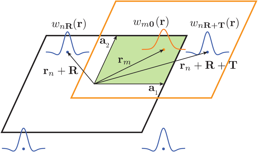
Figure 8. The provenance graph automatically generated by AiiDA when running a Wannier90 calculation for a diamond crystal using Quantum ESPRESSO as the DFT code. Rectangles represent executions of calculations, ellipses represent data nodes, and diamonds are code executables. Graph edges connect calculations to their inputs and outputs. In particular, the following calculations are visible: Quantum ESPRESSO pw.x SCF (dark blue) and NSCF (green), Quantum ESPRESSO ![$ \newcommand{\exec}[1]{{\tt #1.x}} \newcommand{\e}{{\rm e}} \newcommand{\pwtowan}{{\exec{pw2wannier90}}} \pwtowan$](https://content.cld.iop.org/journals/0953-8984/32/16/165902/revision2/cmab51ffieqn585.gif) (brown), and Wannier90 pre-processing (yellow) and minimisation run (purple). The initial diamond structure (light blue) and the final interpolated band structure (dark grey) are also highlighted.
(brown), and Wannier90 pre-processing (yellow) and minimisation run (purple). The initial diamond structure (light blue) and the final interpolated band structure (dark grey) are also highlighted.
Download figure:
Standard image High-resolution image
To demonstrate the usefulness of this approach, we refer to [106] that reports the implementation and verification results of a fully-automated workflow (implemented within AiiDA, using the AiiDA – Wannier90 plugin described in this section) to compute Wannier functions of any material without any user input (besides its crystal structure). In addition, a virtual machine containing the codes (AiiDA with its plugins, Quantum ESPRESSO and Wannier90 including the SCDM implementation described in section 6, and the automation workflows) is distributed. This virtual machine allows any researcher to reproduce the results of the paper and, even more, to perform simulations on new materials using the same protocol, without the need of installing and configuring all codes.
We emphasise that the availability of a platform to run Wannier90 in a fully-automated high-throughput way via the AiiDA – Wannier90 plugin has already proved to be beneficial for the Wannier90 code itself. Indeed, it has pushed the development of additional features or improvements now part of Wannier90 v3.0, including additional output files to facilitate output parsing and improvements in some of the algorithms and their default parameters to increase robustness.
8. Modern software engineering practices
In this section, we describe a number of modern software engineering practices that are now part of the development cycle of the Wannier90 code. In particular, Wannier90 includes a number of tests that are run at every commit via a continuous integration approach, as well as nightly in a dedicated test farm. Version control is handled using git and the code is hosted on the GitHub platform [107]. We follow the fork and pull-request model, in which users can duplicate (fork) the project into their own private repository, make their own changes, and make a pull request (i.e. request that their changes be incorporated back into the main repository). When a pull request is made, a series of tests are automatically performed: the test suite is run both in serial and parallel using the Travis continuous integration platform [108], and code coverage is checked using codecov [109]. If these tests are successful then the changes are reviewed by members of the Wannier90 developers group and, if the code meets the published coding guidelines, it can be merged into the development branch.
In addition, while interaction with end users happens via a mailing-list forum, discussion among developers is now tracked using GitHub issues. This facilitates the maintenance of independent conversation threads for each different code issue, new feature proposal or bug. These can easily reference code lines as well as be referenced in code commit messages. Moreover, for every new bug report a new issue is opened, and pull requests that close the issue clearly refer to it. This approach facilitates tracking back the reasoning behind the changes in case a similar problem resurfaces.
In the remainder of this section we describe more in detail some of these modern software engineering practices.
8.1. Code documentation (FORD)
The initial release of Wannier90 came with extensive documentation in the form of a User Guide describing the methodology, input flags to the program and format of the input and output files. This document was aimed at the end users running the software. Documentation of the code itself was done via standard code comments. In order to foster not only a community of users but also of code contributors to Wannier90, we have now created an additional documentation of the internal structure of the code. This makes the code more approachable, particularly for new contributors. To create this code documentation in a fully automated fashion, we use the FORD (FORtran Documenter) [110] documentation generator. We have chosen this over other existing documentation solutions because of FORD's specific support for Fortran. This tool parses the Fortran source, and generates a hyperlinked (HTML) index of source files, modules, procedures, types and programs defined in the code. Furthermore, it constructs graphs showing the dependencies between different modules and subroutines. Additional information can be provided in the form of special in-code comments (marked with double exclamation marks) describing in more detail variables, modules or subroutines. By tightly coupling the code to its documentation using in-code comments, the documentation maintenance efforts are greatly reduced, decreasing the risk of having outdated documentation. The compiled version of the documentation for the most recent code version is made available on the Wannier90 website [111].
8.2. Testing infrastructure and continuous integration
With the recent opening to the community of the Wannier90 development, it has become crucial to create a non-regression test suite to ensure that new developments do not break existing functionalities of the code. Its availability facilitates the maintenance of the code and ensures its long-term stability.
The Wannier90 test suite relies on a modified version of James Spencer's python testcode.py [112]. This provides the functionality to run tests and compare selected quantities parsed from the output files against benchmarked values.
At present, the Wannier90 test suite includes over 50 tests which are run both in serial and parallel and cover over 60% of the source code (with many modules exceeding 80% coverage). The code coverage is measured with the codecov software [109]. Developers are now required to add tests when adding new features to the code to ensure that their additions work as expected. This also ensures that future changes to the code will never break that functionality. Two different test approaches are implemented, serving different purposes.
First, the Wannier90 repository is now linked with the Travis continuous integration platform [108] to prevent introducing errors and bugs into the main code branch. Upon any commit to the GitHub repository, the test suite is run both in serial and in parallel. Any test failure is reported back to the GitHub webpage. Additionally, for tests run against pull requests, any failed test results in the pull request being blocked and not permitted to merge. Contributors will first need to change their code to fix the problems highlighted in the tests; pull requests are able to be merged only after all tests pass successfully.
Second, nightly automatic tests are run on a Buildbot test farm. The test farm compiles and runs the code with a combination of compilers and libraries (current compilers include GFortran v6.4.0 and v7.3.0, Intel Fortran Compiler v17 and v18, and PGI compiler v18.05; current MPI libraries include Open MPI v1.10.7 and v3.1.3, Intel MPI v17 and MVAPICH v2.3b). This ensures that the code runs correctly on various high-performance computer (HPC) architectures. More information on the test farm can be found on the Wannier90 GitHub wiki website [113].
In addition to these tests, we have implemented git pre-commit hooks to help keep the same code style in all source files. The current pre-commit hooks run Patrick Seewald's Fortran source code formatter fprettify [114] to remove trailing whitespaces at the end of a line and to enforce a consistent indentation style. These precommit hooks, besides validating the code, can reformat it automatically. Developers may simply run the formatter code to convert the source to a valid format. If a developer installs the pre-commit hooks, these will be run automatically before every commit. Even if this is not the case, these tests are also run on Travis; therefore, a pull request that does not conform to the standard code style cannot be merged before the style is fixed.
8.3. Command-line interface and dry-run
The command-line interface of the code has been improved. Just running ![$ \newcommand{\exec}[1]{{\tt #1.x}} \newcommand{\e}{{\rm e}} \exec{wannier90}$](https://content.cld.iop.org/journals/0953-8984/32/16/165902/revision2/cmab51ffieqn592.gif) without parameters shows a short explanation of the available command line options. In addition, a -v flag has been added to print the version of the code, as well as a new -d dry-run mode, that just parses the input file to perform all needed checks of the inputs without running the actual calculation. The latter functionality is particularly useful to be used in input validators for Wannier90 or to precalculate quantities computed by the code at the beginning of the simulation (such as nearest-neighbour shells, b-vectors or expected memory usage) and use this information to validate the run or optimise it (e.g. to decide the parallelisation strategy within automated AiiDA workflows).
without parameters shows a short explanation of the available command line options. In addition, a -v flag has been added to print the version of the code, as well as a new -d dry-run mode, that just parses the input file to perform all needed checks of the inputs without running the actual calculation. The latter functionality is particularly useful to be used in input validators for Wannier90 or to precalculate quantities computed by the code at the beginning of the simulation (such as nearest-neighbour shells, b-vectors or expected memory usage) and use this information to validate the run or optimise it (e.g. to decide the parallelisation strategy within automated AiiDA workflows).
8.4. Library mode
Wannier90 also comes with a library mode, where the core code functionality can be compiled into a library that can then be linked by external programs. This library mode is used as the default interaction protocol by some interface codes. The library mode provides only support for a subset of the full functionality, in particular at the moment it only supports serial execution. We have now added and improved support for the use of excluded bands also within the library mode. Moreover, beside supporting the generation of a statically-linked library, we now also support the generation of dynamically-linked versions. Finally, we have added a minimal test code, run together with all other tests in the test suite, that serves both to verify that the library functionality works as expected, and as an example of the interface of the library mode.
9. Conclusions and outlook
Wannier90 v2.0 was released in October 2013 with a small update for v2.1 in January 2017. The results and developments of the past years, presented in this work, were released in Wannier90 v3.0 in February 2019. Thanks to the transition of Wannier90 to a community code, Wannier90 includes now a large number of new functionalities and improvements that make it very robust, efficient and rich with features. These include the implementation of new methods for the calculation of WFs and for the generation of the initial projections; parallelisation and optimisations; interfaces with new codes, methods and infrastructures; new user functionality; improved documentation; and various bug fixes. The effect of enlarging the community of developers is not only visible in the large number of contributions to the code, but also in the modern software engineering practices that we have put in place, that help improve the robustness and reliability of the code and facilitate its maintenance by the core Wannier90 developers group and its long-term sustainability.
The next major improvement that we are planning is the implementation of a more robust and general library mode. The features that we envision are: (1) the possibility to call the code from C or Fortran codes without the need to store files but by passing all variables from memory; (2) a more general library interface that is easily extensible in the future when new functionality is added; and (3) the possibility to run Wannier90 from a parallel MPI code, both by running each instance in parallel and by allowing massively-parallel codes to call, in parallel, various instances of Wannier90 on various structures or with different parameters. This improvement will demand a significant restructuring of most of the codebase and requires a good design of the new interface. Currently we are drafting the new library interface, by collecting feedback and use cases from the various contributors and users of the code, to ensure that the new library mode can be beneficial to all different possible use cases.
Acknowledgments
We acknowledge code contributions by Daniel Aberg (w90pov code), Lampros Andrinopoulos (w90vdw code), Pablo Aguado Puente (![$ \newcommand{\module}[1]{{\tt #1.F90}} \module{gyrotropic}$](https://content.cld.iop.org/journals/0953-8984/32/16/165902/revision2/cmab51ffieqn593.gif) module), Raffaello Bianco (k-slice plotting), Marco Buongiorno Nardelli (dosqc v1.0 subroutines upon which some of
module), Raffaello Bianco (k-slice plotting), Marco Buongiorno Nardelli (dosqc v1.0 subroutines upon which some of ![$ \newcommand{\module}[1]{{\tt #1.F90}} \module{transport}$](https://content.cld.iop.org/journals/0953-8984/32/16/165902/revision2/cmab51ffieqn594.gif) is based), Stefano de Gironcoli (
is based), Stefano de Gironcoli (![$ \newcommand{\exec}[1]{{\tt #1.x}} \newcommand{\e}{{\rm e}} \newcommand{\pwtowan}{{\exec{pw2wannier90}}} \pwtowan$](https://content.cld.iop.org/journals/0953-8984/32/16/165902/revision2/cmab51ffieqn595.gif) interface to Quantum ESPRESSO), Pablo Garcia Fernandez (matrix elements of the position operator), Nicholas Hine (w90vdw code), Young-Su Lee (specialised
interface to Quantum ESPRESSO), Pablo Garcia Fernandez (matrix elements of the position operator), Nicholas Hine (w90vdw code), Young-Su Lee (specialised  -point routines and transport), Antoine Levitt (preconditioning), Graham Lopez (extension of
 ![$ \newcommand{\exec}[1]{{\tt #1.x}} \newcommand{\e}{{\rm e}} \newcommand{\pwtowan}{{\exec{pw2wannier90}}} \pwtowan$](https://content.cld.iop.org/journals/0953-8984/32/16/165902/revision2/cmab51ffieqn597.gif) to add terms needed for orbital magnetisation), Radu Miron (constrained centres), Nicolas Poilvert (transport routines), Michel Posternak (original plotting routines), Rei Sakuma (symmetry-adapted Wannier functions), Gabriele Sclauzero (disentanglement in spheres in k-space), Matthew Shelley (transport routines), Christian Stieger (routine to print the U matrices), David Strubbe (various bug fixes and improvements), Timo Thonhauser (extension of
to add terms needed for orbital magnetisation), Radu Miron (constrained centres), Nicolas Poilvert (transport routines), Michel Posternak (original plotting routines), Rei Sakuma (symmetry-adapted Wannier functions), Gabriele Sclauzero (disentanglement in spheres in k-space), Matthew Shelley (transport routines), Christian Stieger (routine to print the U matrices), David Strubbe (various bug fixes and improvements), Timo Thonhauser (extension of ![$ \newcommand{\exec}[1]{{\tt #1.x}} \newcommand{\e}{{\rm e}} \newcommand{\pwtowan}{{\exec{pw2wannier90}}} \pwtowan$](https://content.cld.iop.org/journals/0953-8984/32/16/165902/revision2/cmab51ffieqn598.gif) to add terms needed for orbital magnetisation), as well as the participants of the first Wannier90 developers meeting in San Sebastián (Spain) in 2016 for useful discussions (Daniel Fritsch, Victor Garcia Suarez, Pablo Garcia Fernandez, Jan-Philipp Hanke, Ji Hoon Ryoo, Jürg Hutter, Javier Junquera, Liang Liang, Michael Obermeyer, Gianluca Prandini, Christian Stieger, Paolo Umari). The WDG acknowledges financial support from the NCCR MARVEL of the Swiss National Science Foundation, the European Union's Centre of Excellence E-CAM (Grant No. 676531), and the Thomas Young Centre for Theory and Simulation of Materials (Grant No. TYC-101).
to add terms needed for orbital magnetisation), as well as the participants of the first Wannier90 developers meeting in San Sebastián (Spain) in 2016 for useful discussions (Daniel Fritsch, Victor Garcia Suarez, Pablo Garcia Fernandez, Jan-Philipp Hanke, Ji Hoon Ryoo, Jürg Hutter, Javier Junquera, Liang Liang, Michael Obermeyer, Gianluca Prandini, Christian Stieger, Paolo Umari). The WDG acknowledges financial support from the NCCR MARVEL of the Swiss National Science Foundation, the European Union's Centre of Excellence E-CAM (Grant No. 676531), and the Thomas Young Centre for Theory and Simulation of Materials (Grant No. TYC-101).