

Abstract
Block copolymer-based energy storage emerges as an active interdisciplinary research field. This topical review presents a survey of the recent advances in block copolymers for energy storage. In the first section, we introduce the background of electrochemical energy storage and block copolymer thermodynamics. In the second section, we discuss the current understandings of block copolymer chemistry, processing, pore size, and ionic conductivity. In the third section, we summarize the design principles and state-of-the-art applications of block copolymers in three energy storage devices, namely, supercapacitors, dielectric capacitors, and batteries. Lastly, we present our perspectives on future possible breakthroughs and associated challenges that are essential to propel the development of advanced block copolymers for energy storage. We expect the review to encourage innovative studies on integrating block copolymers into energy storage applications.
Export citation and abstract BibTeX RIS
1. Introduction
High-performance energy storage is central to smart management of energy from both fossil fuels and renewable resources (e.g. solar, hydro, and wind) [1]. Especially for renewable energy that is intermittent and fluctuant, the energy storage is indispensable to ensure stable and reliable dissemination on demand. Since electricity is the most convenient and economical form of energy in modern society, electrical energy storage is of paramount importance and represents one of the most active research fields involving physics, chemistry, materials, and engineering. Typical portable electrical energy storage devices include supercapacitors, dielectric capacitors, and batteries.
Block copolymers consist of two or more chemically distinct and incompatible polymer blocks covalently linked together [2, 3]. Depending on the number of blocks, linear block copolymers are categorized into di-block and multi-block (tri-block, tetra-block, etc) copolymers (figure 1(a)). Block copolymers are typically synthesized by polymerizing the first block, followed by the growth of additional block(s) from the reactive end(s) of the previous block(s). The widely practiced synthesis methods include reversible addition fragmentation chain transfer (RAFT) polymerization [4], atom transfer radical polymerization (ATRP) [5], ring-opening metathesis polymerization (ROMP) [6], living cationic polymerization [7], and anionic polymerization [8]. A notable feature of block copolymers is their capability of self-assembly into diverse morphologies [9, 10]. Because the constituent blocks are immiscible with one another, blocks of the same chemistry tend to aggregate and repel blocks of different chemistries when subjected to solvent or thermal annealing. However, the covalent links prohibit macrophase separation but induce microphase separation into mesoscopic structures. Figure 1(b) shows a typical core–shell micelle self-assembled by an A–B di-block copolymer.
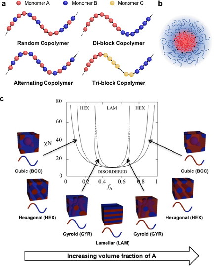
Figure 1. (a) Illustrations of the structures of typical linear copolymers. Random copolymers contain different monomers distributed randomly in polymer chains. Alternating copolymers have alternating A and B monomers that constitute polymer chains. Block copolymers are composed of two (di-block) or more (tri-block, tetra-block, etc) polymers covalently connected together. (b) A micelle self-assembled by a linear A–B di-block copolymer. Reproduced from [11] with permission from AAAS. (c) Phase diagram of a linear A–B di-block copolymer. Depending on χN and f , di-block copolymers self-assemble into thermodynamically stable morphologies such as body-center-cubic spheres, hexagonally packed cylinders, cubic bicontinuous gyroids and lamellae. Reproduced with permission from [12]. Copyright © 1996 American Chemical Society.
Download figure:
Standard image High-resolution imageThe self-assembly of block copolymers can be described by the Flory–Huggins theory. The molar Gibbs free energy change (ΔG, J) of mixing two polymers, A and B, can be described as:
where R is the gas constant (=8.314 J K−1 mol−1); T is temperature (K); V is total volume (m3);  and
and  are the volume fraction and molar volume (m3 mol−1) of block i (i = A or B), respectively;
  is the reduced molar volume (m3 mol−1) of a specific polymer segment;
  is the dimensionless Flory–Huggins interaction parameter that correlates to the free-energy cost per monomer upon mixing A with B.
  can be quantitatively expressed as:
where Z is the coordination number (the number of nearest-neighboring monomers); kB is the Boltzmann constant (=1.38 × 10⁻²³ J K−1);  ,
,  and
and  are the interaction energies between A and B, A and A, B and B, respectively. Equation (2) pertains to an ideal situation that does not consider any contributions from the changes in volume or local packing order after mixing. To account for the non-ideal contributions, an effective interaction parameter,
  , is often used, which scales inversely to temperature and follows equation (3).
where the first and second terms represent the entropic and enthalpic contributions, respectively [13].
In equation (1), the sum of the last two terms i.e.  , are related to the entropy change upon mixing two polymers and are always negative since
  . Therefore, the first enthalpy-associated term,
  , must be positive and
  must be large enough to ensure positive ΔG that triggers spontaneous de-mixing of the two blocks, i.e. self-assembly of the block copolymer.
The morphology of the thermodynamically equilibrated morphologies of a di-block copolymer are determined by two factors: χN (the product of  and the degree of polymerization, N), and
  (or
(or  ). Figure 1(c) depicts a theoretical phase diagram of a linear A–B di-block copolymer. To trigger the self-assembly of a given block copolymer with a fixed
  (or
(or  ), χN must be higher than the order–disorder transition (ODT), i.e. the boundary between the disordered state and the ordered microphases. Typical microphases include cubic (or spherical), hexagonal, gyroid, and lamellar morphologies. Gyroid and lamellar structures are bi-continuous. In the rest phases, the minority blocks are segregated and the majority blocks are continuous. The self-assembly of tri-block copolymers is more complicated than that of di-block copolymers, resulting in astonishingly diverse and complex nanostructures [14–16].
The rich phase behavior of block copolymers provides versatile tools for building well-defined nanostructures in energy storage devices. This topical review first summarizes the fundamental understandings of block copolymers in energy science and then presents the recent progress of using block copolymers as components in supercapacitors, dielectric capacitors and batteries. In section 2, we will elaborate the state-of-the-art understandings of how the composition and structure of block copolymers affect the pore size and ionic conductivities. In section 3, we will show various examples of block copolymer-derived components for supercapacitors (section 3.1), dielectric capacitors (section 3.2), and rechargeable batteries (section 3.3). In the last section (section 4), we will summarize and share our outlook and perspective on future opportunities, possible breakthroughs and remaining challenges.
2. Fundamentals of block copolymers for energy storage
This section presents the fundamentals of how the block copolymer composition and structure influence the pore size and ionic conductivity. The two properties are closely related to the performance of block copolymers in energy storage devices. For instance, the pore size determines the ion-accessible surface area, capacitance (or capacity), rate capability, power density, and energy density of electrodes. The ionic conductivity influences the resistance and power output of electrolytes.
2.1. Pore size
Pore size is a structural parameter that largely determines the performance of electrical energy storage devices. It affects not only the surface areas and thus the capacitances (or capacities) of electrodes, but also the ion diffusion in ion-exchange membranes and separators. This section summarizes the approaches to tuning the pore sizes of block copolymer films and block copolymer derived carbon nanostructures.
2.1.1. Degree of polymerization.
For block copolymers, the pore size is directly correlated to the domain size of the sacrificial blocks, which is correlated to the degree of polymerization (N), or the molecular weight. For example, polyacrylonitrile-block-poly(butyl acrylate) (PAN-b-PBA) is a typical precursor for mesoporous carbon powder [17], which contains a high carbon yield block of PAN and a sacrificial block of PBA (figure 2(a)). After pyrolysis, the pore sizes, either measured by Brunauer–Emmet–Teller (BET) or calculated from small angle x-ray scattering (SAXS), increased with the total degree of polymerization (DPtot, figure 2(b)). The pore interconnectivity also increased as the pores broadened (figure 2(c)). Other reports on PAN-b-PMMA [18] and dopamine-doped PS-b-PEO [19] also validate that the degree of polymerization is an important parameter to tune the pore size of carbon films.
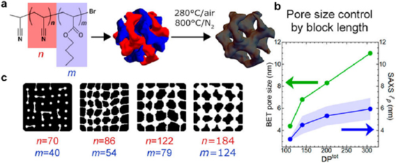
Figure 2. (a) Synthesis of mesoporous carbon from PAN-b-PBA. (b) BET pore size and SAXS lp (lp, the length of inhomogeneity that represents the average length of a continuous block) increase with the total degree of polymerization (DPtot). (c) Qualitative illustration of pore size and pore interconnectivity as the degrees of polymerization of PAN and PBA are increased. Reproduced with permission from [17]. Copyright © 2017 American Chemical Society.
Download figure:
Standard image High-resolution image2.1.2. Thermal annealing temperature and solvent.
The thermal and solvent annealing conditions control the pore size of mesoporous carbons during the self-assembly process of block copolymers. For instance, upon thermal or solvent annealing, the spin-casted PAN-b-PMMA thin films self-assembled into microphases with different PAN and PMMA domain sizes [20]. The subsequent pyrolysis decomposed PMMA to generate pores and carbonized PAN to form carbon matrices (figure 3(a)). The mesopore size of the resultant carbon thin films increased from ~40 to 48 nm as the annealing temperature was increased from 100 °C to 300 °C (figure 3(b), black curve). In general, the center-to-center spacing (Lo) of both the block copolymer domains (figure 3(b), blue curve) and carbon pores (figure 3(b), red curve) increased as the temperature was increased. The unique temperature-dependence of the pore size and domain spacing is attributed to the thermal expansion of PMMA and PAN, as well as the cyclization of PAN [21]. The thermal expansion coefficients of PAN and PMMA are ~1.4 × 10⁻⁵ K−1 [22] and ~7.0–9.3 × 10⁻⁵ K−1 [23], respectively. The higher thermal expansion coefficient of PMMA than that of PAN suggests that when increasing the thermal annealing temperature, PMMA expands faster than PAN and forms larger domains. Because PAN is crosslinked due to cyclization, the subsequent removal of PMMA results in larger pore sizes. Additionally, the degree of PAN cyclization increases with increasing temperature, which further reduces the free volume of PAN, shrinks the PAN domain size, and increases the pore size in the carbon after pyrolysis. The pore size tunability by thermal annealing temperature was corroborated by others [24, 25]. In addition, solvent annealing in various solvent vapors also produced carbon films with various pore sizes and center-to-center spacings (figure 3(c)). The controllability of solvent annealing is rooted in the different affinities of the solvent molecules to polymer blocks.
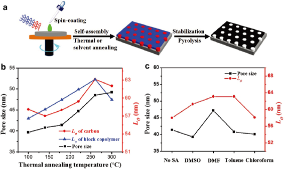
Figure 3. (a) Schematic illustration of the key steps for preparing mesoporous carbon thin films from PAN-b-PMMA. The blue and red regions are PMMA and PAN, respectively. (b) and (c) The relationships between the pore size, the center-to-center spacing (Lo) of the mesoporous carbon thin films obtained under various (b) thermal annealing temperatures and (c) solvents. Reproduced with permission from [20]. John Wiley & Sons. © 2017 WILEY-VCH Verlag GmbH & Co. KGaA, Weinheim.
Download figure:
Standard image High-resolution image2.1.3. Polymer blend.
The pore size can also be tuned by blending block copolymers of different degrees of polymerization, or mixing block copolymers with homopolymers. The pore size (D) of carbon films derived from a binary blend is proportional to the weight fractions of each component:

where Di and xi are the pore size and the weight fraction of component i (i = 1 and 2), respectively. For example, blending polystyrene-block-poly(4-vinylpyridine) (PS-b-P4VP) of different molecular weights can effectively tune the mesopore sizes of the resultant carbon films from ~20 to 50 nm (figure 4) [26]. In addition, because homopolymers selectively swell the corresponding block of the block copolymers [27, 28], the amount of homopolymers can tailor the pore size. A typical example is PS-b-P4VP containing 8, 16 and 31 wt.% of P4VP, which have average pore sizes of 22, 25 and 48 nm, respectively [29]. The tuning of pore sizes by polymer blends provides enormous simplicity and avoids arduous syntheses of block copolymers with various molecular weights.
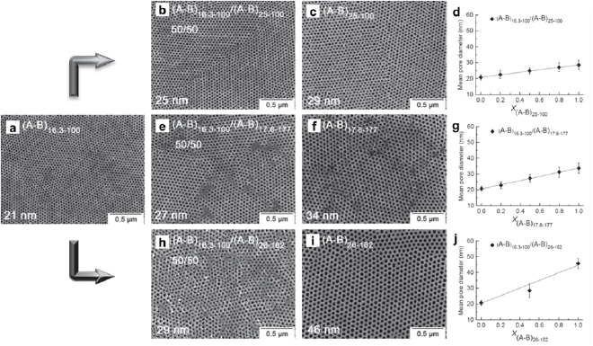
Figure 4. Top-down SEM images of mesoporous carbon films derived from various block copolymers: (a), (c), (f) and (i) pure PS-b-P4VP of various compositions. (A–B)x-y : x and y denote the molecular weight (in kDa) of PS-b-P4VP and the weight percentage (in %) of P4VP, respectively. (b), (e) and (h) 50/50 blends of the block copolymers. (d), (g) and (j) The mean pore diameter as a function of the blend composition. Reproduced with permission from [26]. John Wiley & Sons. © 2014 WILEY-VCH Verlag GmbH & Co. KGaA, Weinheim.
Download figure:
Standard image High-resolution image2.2. Ionic conductivity
For block copolymer electrolytes in energy storage devices, ionic conductivity is a crucial figure-of-merit. This section discusses how morphology, temperature, polymer molecular weight, and salt affect the ionic conductivities of block copolymer electrolytes.
2.2.1. Morphology.
The ionic conductivities of block copolymer electrolytes strongly depend on their morphologies. Typically, the ionic conductivity ( , in S m−1) of a microphase-separated block copolymer can be derived from the effective medium theory [30]. In the simplest case,
  increases linearly with the ionic conductivity (S m−1) of the pure conducting phase at the same salt concentration (
 ):
):
where the dimensionless  ,
,  , and
, and  are the morphology factor, tortuosity factor, and volume fraction of the conducting phase, respectively.
  accounts for the morphological influence of the conducting phase on the ion mobility, and
  reflects the retardance to the ion diffusion caused by the tortuosity of the conducting phase. Table 1 summarizes the typical values of
  and
and  for linear A–B di-block copolymers after self-assembly into thermodynamically stable microphases.
Table 1. Morphology and tortuosity factors of block copolymer electrolytes [31].
| Morphology | Conducting phase |  |
τ−1 |
|---|---|---|---|
| Sphere | Minority | 0 |
1 |
| Majority | 1 | 2/(3 − f ) |
|
| Cylinder | Minority | 1/3 | 1 |
| Majority | 1 | 1/(2 − f ) | |
| Gyroid | Minority | 1 | ½ |
| Majority | 1 | 4/5 | |
| Lamella | N.A. | 2/3 | 1 |
aThe maximal and minimal values of both  and τ−1 are 1 and 0, respectively. '1' represents zero impedance for ion diffusion. '0' means complete blockage for ion flow.
bf represents the volume fraction of the ion-conducting phase.
and τ−1 are 1 and 0, respectively. '1' represents zero impedance for ion diffusion. '0' means complete blockage for ion flow.
bf represents the volume fraction of the ion-conducting phase.
Generally for a block copolymer electrolyte, the tortuosity of its conducting phase can be evaluated by the empirical Bruggeman equation (9) [32]:

where  and
and  are empirically determined parameters for each block copolymer electrolyte. Equation (6) is obtained under the assumption of
  .
.
The impact of morphology on the ionic conductivity is well demonstrated by a study on LiCF3SO3-doped PEO dendron electrolytes with two molecular weights (1-Li+: 4600 Da, 2-Li+: 7500 Da) [33]. As the temperature was increased, the morphology of 1-Li+ evolved from crystalline (k1 and k2), micellar (mc) to disordered (dis) mesophase. The ionic conductivity decreased sharply as the electrolyte changed from k2 to mc, but did not change substantially during the mc-dis transition (figure 5(a)). 2-Li+ transited from crystalline (k1 and k2) to hexagonal columnar (hex), and to continuous cubic (cc) structure. Its ionic conductivity increased by nearly an order of magnitude at the hex-cc phase transition. In comparison with mc and dis whose conducting domains were discontinuous, the conducting domains in hex and cc were continuous and facilitated ion diffusion, as corroborated by others [34–36].
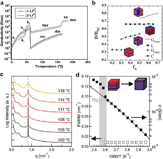
Figure 5. (a) The relationship between temperature and ionic conductivity of two LiCF3SO3-doped PEO dendron electrolytes of various phases: k1 and k2—crystalline, hex—hexagonal columnar, lam—lamellar, cc—continuous cubic, dis—disorder, dec—decomposed. The total molecular weights of 1-Li+ and 2-Li+ are 4600 and 7500 Da, respectively. Reproduced from [33], with permission from AAAS. (b) Ion diffusion coefficients of various morphologies normalized to that of the unconstrained diffusion (D/DNC) versus the volume fraction of the ion-conducting domains (f A, red). Reproduced with permission from [37]. Copyright © 2018, The American Chemical Society. (c) SAXS spectra of SEO electrolyte ([LiTFSI]:[EO] = 0.085) at various temperatures. The dashed line highlights the diffraction peak from the conducting PEO block. This peak broadens with increasing temperature, indicating the electrolyte becomes increasingly disordered. (d) Ionic conductivity and structure order of SEO electrolyte ([LiTFSI]:[EO] = 0.085) as a function of temperature. FWHM is inversely proportional to the structure order. The gray band highlights the lamellar-to-disorder transition. (c) and (d) are reproduced from [38]. Copyright © 2012 American Chemical Society.
Download figure:
Standard image High-resolution imageA series of experiments have shown an inverse correlation between ionic conductivity and structural tortuosity. For example, the Li+ diffusion coefficient through a lamellar polystyrene-block-poly(ethylene oxide) (SEO) electrolyte decreased by ~80% after the adjacent poly(ethylene oxide) (PEO) lamellar domains became connected [39]. The interconnection of the conducting lamellar domains induced anisotropic ion flow, augmented structural tortuosity and hence reduced ion mobility. Based on random-walk molecular simulations [37], the ionic conductivity decreased with the tortuosity, as the conducting phase (red) changed from gyroid majority to lamellae, to gyroid minority, and to cylinders (figure 5(b)).
However, other experiments suggest that the ionic conductivity does not necessarily always increase inversely to the structure tortuosity. A number of reports have shown that the disordered phase with the highest tortuosity favored rapid ion diffusion [38, 40–42]. For example, when a lithium(trifluoromethylsulfonyl)imide (LiTFSI)-containing SEO electrolyte evolved from lamellar to disordered, its ionic conductivity abruptly increased nearly twice (figures 5(c) and (d)) [38]. In contrast, Wanakule et al concluded that neither order-to-order transitions (OOT) nor ODT significantly influenced the ionic conductivity of a LiTFSI-doped SEO electrolyte [43]. The exact causes of the discrepancies in the tortuosity effect are unclear but may be linked to various factors, such as the diverse natures of the different electrolytes, the presence of various structural defects, the non-uniform salt concentration within the conducting blocks, and the irregular ion partition between the conducting and insulating phases.
2.2.2. Temperature.
The ionic conductivity of a given microstructure generally increases as the temperature is increased. The ionic conductivity and temperature relationship can be described by the Vogel–Tammann–Fulcher (VTF) equation [41, 44],
where A is a pre-exponential factor that depends on ion concentration (S m−1); T is the temperature (K); Ea is the effective ion-transport activation energy (J mol−1); and T0 is the reference temperature (K) that is typically set to the glass transition temperature (Tg) of the ion-conducting block. Equation (8) is specifically derived from equation (7) to evaluate the ionic conductivity of a block copolymer electrolyte with isotropic, well-connected and strongly confined conducting phases (i.e. the phases that contain ionic liquids): [45]
where  is the volume fraction of the added ionic liquid; B is a constant associated with the ion-transport activation energy (J mol−1); and Tg depends on the composition and the concentration of the ionic liquid. Both Tg and B are characteristic for a given polymer/ionic liquid combination.
2.2.3. Molecular weight.
For a given microphase, the molecular weight changes the domain size of the conducting block and thus alters the ionic conductivity. For a lamellar SEO electrolyte with a molecular weight of over 10.4 kDa, its ionic conductivity increased as the molecular weight was increased [46], due to the increasing PEO domain size. At low molecular weights, the PS and PEO domains were weakly segregated and the diffusion of Li+ was hindered by the polymer chain entanglement. As the molecular weight was increased, so was the segregation strength, and therefore the PEO domains gradually broadened. Because the PEO chains in the central zone of the PEO domain were unrestrained, the mobility of Li+ was boosted. Based on the self-consistent field theory, the impedance to Li+ conduction near the PEO/PS interface stemmed from the edge stress that interfered Li+-PEO coordination [47].
By reducing the molecular weights, the conducting domains narrowed and facilitated ion diffusion. Compared to a conventional SEO electrolyte, S(EO)3 with three shorter PEO arms showed an enhanced conductivity (figure 6(a)) [48]. SEM demonstrated that the S(EO)3 self-assembled into PEO lamellar domains narrower than SEO (figures 6(b) and (c)). It was believed that the Li+ ions in the narrow channels tended to flow straightly through each PEO lamella due to the structure confinement, while those in the wide diffusion channels swayed around and resulted in slow movement across the electrolyte (figure 6(d)). Due to the structure confinement, the Li+ concentration in the narrow channels (1.92 mmol cm−3) was higher than that in the wide channels (1.57 mmol cm−3).
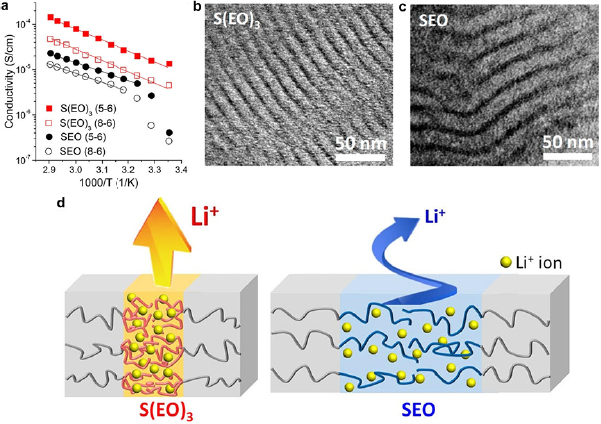
Figure 6. (a) The Arrhenius plots of S(EO)3 and SEO electrolytes with various molecular weights. S(EO)3 (X-Y): X and Y denote the molecular weights of PS and (EO)3 in kDa. The solid lines are fitting curves based on the Arrhenius model. (b) and (c) TEM images of (b) S(EO)3 and (c) SEO. The bright and dark domains are PS and PEO (stained with RsO4), respectively. The S(EO)3 electrolyte has narrower conducting channels than SEO. (d) Schematic illustration of the different ion diffusion dynamics in S(EO)3 and SEO. S(EO)3 has a narrower PEO domain width with less tortuosity and thus higher ionic conductivity than SEO. Reproduced with permission from [48]. Copyright © 2018 American Chemical Society.
Download figure:
Standard image High-resolution imageAdditionally, the molecular weights determine the crystallinity of the conducting block and therefore the ionic conductivity. A typical example is the poly[oligo(oxyethylene)methacrylate] with short PEO side chains that has lower crystallinity and thus higher ionic conductivity than SEO [49–52]. The underlying mechanism is that the polymer chain mobility increases as the crystallinity decreases, which helps with the ion conduction.
2.2.4. Salt.
The ionic conductivities of block copolymer electrolytes depend on the salt incorporated in the conducting blocks, because the cation–anion interactions affect the ion mobility and therefore the ionic conductivity. Generally, conducting polymers with strong acid groups tend to be highly conductive [53, 54]. For example, the ionic conductivity of PEO-CF3SO3Li at 373 K was ~4 × 10⁻⁴ S cm−1, approximately one order of magnitude higher than that of PEO-CH3COOLi at an identical lithium concentration [53]. Because CF3SO3H is more acidic than CH3COOH, the interaction strength between  is much weaker than that of CH3COO−/Li+, which leads to a higher Li+ conductivity. Recently, the addition of multiple salts [55] and the blending of salts with ionic liquids [56] were proven to be effective in improving the ionic conductivities of SEO. The improved ionic conductivity was correlated to multiple factors including decreased crystallinity, reduced Tg of PEO, improved PEO chain flexibility, and enhanced solubility of the lithium salt.
The Li+ concentration strongly influences the ionic conductivities of SEO electrolytes. The ionic conductivity of a SEO electrolyte displayed three local maxima at r = ~0.14, ~0.28 and ~0.34 (r represents the concentration ratio of Li+ to the EO unit) [57]. In contrast, the ionic conductivity of a PEO electrolyte only peaked at r ~ 0.06 (figure 7(a)). These characteristics do not follow the effective medium theory (equation (5)), which states that the number of the ionic conductivity maxima and their r values of a block copolymer electrolyte should be the same as those of the corresponding homopolymer electrolyte. Alternatively, the anomalous behavior of the ionic conductivity of SEO was correlated to the different morphologies and the deviation in the Tg from the PEO electrolyte (figure 7(b)).

Figure 7. (a) Ionic conductivities at 90 °C and (b) glass transition temperature (Tg) of LiTFSI-doped SEO and LiTFSI-doped PEO. r is the concentration ratio of Li+ to the EO unit. Error bars are standard deviations of at least three samples. The open hourglass data points are ionic conductivities of LiTFSI-doped PEO reported by Lascaud et al [60]. The dashed lines highlight the stoichiometric ratios of PEO:LiTFSI. Reproduced with permission from [57]. Copyright © 2018 American Chemical Society.
Download figure:
Standard image High-resolution imageIn addition, the partition and distribution of the ions in the conducting domains of single-ion electrolytes (electrolytes that conduct only cations or anions, section 3.3.3) can profoundly modify their ionic conductivities. The incorporation of free counterions in the conducting domains reduced the overall conductivity of single-ion electrolyte poly(lauryl methacrylate)-block-poly(lithium methacrylate)-block-poly[(oxyethylene)9 methacrylate] (PLMA-b-PLiMA-b-POEM) by more than ten times [58]. Conversely, the incorporation of mobile ions in the conducting domains of single-ion electrolyte poly(ethylene oxide)-block-polystyrenesulfonyllithium(trifluoromethylsulfonyl)imide (PEO-b-PSLiTFSI) enhanced the ionic conductivity by over three orders of magnitude [59].
3. Applications of block copolymers in energy storage
3.1. Supercapacitors
Supercapacitors are ultrahigh power electrochemical energy storage devices. Because supercapacitors store and deliver electrical energy rapidly (typically within seconds), they are used in applications that require high power uptake and output, for instance, gantry cranes [61]. A supercapacitor is composed of a positive electrode, a negative electrode, a piece of separator sandwiched between the two electrodes to prevent electric short circuits, and an ion-containing electrolyte (figure 8(a)). One of the most important figure-of-merits of a supercapacitor is capacitance, which measures the amount of energy stored inside. Another is the rate capability that represents how much capacitance retained at high charge–discharge rates. Good supercapacitors must provide high capacitances across a broad range of charge–discharge rates.

Figure 8. (a) A schematic depicting the structure of a typical supercapacitor composed of cathode, separator, and anode sealed in a package. The metal contacts are connected to the two electrodes. (b) The structure of an EDL. IHP: inner Helmholtz layer, a layer of counterions electro-adsorbed on the charged electrode surface; OHP: outer Helmholtz layer, a layer of loosely packed ions with opposite charges to the ions in IHP. (c) Representative pseudocapacitive processes: protonation and de-protonation of hydrous RuO2 in acidic electrolytes. Reproduced from [64], with permission of The Royal Society of Chemistry.
Download figure:
Standard image High-resolution imageThere are two types of capacitance: electrical double layer (EDL) capacitance and pseudocapacitance. EDL capacitance is associated with EDLs formed at the electrode/electrolyte interfaces (figure 8(b)). The electrodes are typically made of porous carbons and the energy is stored as two layers of electro-adsorbed ions on the surfaces. Differently, pseudocapacitance involves Faradic redox reactions (figure 8(c)) that change the valence states of pseudocapacitive materials (e.g. metal oxides, metal nitrides, and conjugated polymers). Pseudocapacitors differ from batteries in that the redox reactions must be kinetically fast and the pseudocapacitive electrodes must not experience any phase change throughout the reactions [62].
According to the simplest Helmholtz model, the EDL capacitance (CEDL, in F g−1) is determined by the ion-accessible surface area of the electrodes (S, in m2), the relative permittivity of the electrolyte (εr) and the separation distance between the ions in the electrolyte and the charges on the electrode surface (d):
where ε0 is the electric permittivity in vacuum (=8.854 × 10⁻¹² F m−1). Because the ions are small in size, d is at the Ångström scale and therefore the capacitance is often ultrahigh. For a given electrolyte, since εr and d are fixed, S becomes the most determining parameter for capacitance. Thus, electrically conductive materials with ultrahigh ion-accessible surface areas and abundant pores are mostly used as supercapacitor electrodes. Pseudocapacitance is more complex than EDL capacitance. Considering the length limit of this review, we will not provide additional details about pseudocapacitance. Readers may refer to other review articles [62, 63].
3.1.1. Block copolymer electrodes.
Block copolymers are widely used as soft-templates in conjunction with carbon precursors to prepare mesoporous carbon electrodes. Particularly, the mesoporous carbons derived from block copolymer templates possess high surface areas and ordered mesopores. Pluronic® F127, a.k.a. P-123 or Poloxamer 407 (PEO-b-PPO-b-PEO), is a commonly used block copolymer template [65–87]. Other block copolymers with strong segregation strengths are also potent templates, such as poly(ethylene glycol)-block-poly(4-vinylpyridine) (PEG-b-P4VP) [88], PS-b-P4VP [89], PS-b-PEO (SEO) [80, 90–92], and PS-b-poly(2-vinylpyridine)-b-PEO [93]. Since these block copolymer templates are thermally instable and have low char yields, they are infiltrated with carbon precursors to generate mesoporous carbons. Typical carbon precursors are resorcinol-formaldehyde (RF) resin [74, 81, 83, 87, 89, 94], phenolic resin (PF) [68, 72, 73, 76, 78, 82, 84, 85, 90, 93], amino acid [69], graphene oxide [70], polybenzoxazine [71], polyaniline [91], melamine [75], fructose [88], chitosan [77], furfuryl alcohol [86], and dopamine [19, 92]. High temperature treatment produces replicas of mesoporous carbon by carbonizing the infiltrated carbon precursors and removing the block copolymer templates.
Block copolymers are also prominent precursors of mesoporous carbons that can be directly used as supercapacitor electrodes. A thermal liable sacrificial polymer block creates mesopores upon thermal decomposition or sublimation, while a high-char-yield polymer block is used as the carbon precursor. Example sacrificial polymers include poly(butyl acrylate) (PBA) [95, 96], polystyrene (PS) [19, 25, 97–99], poly(ethylene oxide) [19, 97, 100], poly[2-(methacryloyloxy)ethyl]trimethylammonium chloride (PDMC) [101], poly(acrylic acid) (PAA) [102], poly(propylene oxide) (PPO) [94] and poly(methyl methacrylate) (PMMA) [18, 103–105]. Typical high char yield polymers include polyacryonitrile (PAN) [18, 25, 96, 103–106] and poly(vinylidene chloride) (PVDC) [99]. Particularly, carbons derived from N-rich polymers such as PAN are inherently doped with pseudocapacitive nitrogen, which increases the capacitances of the carbon electrodes.
PAN-b-PMMA-derived porous carbon fibers (PCFs) are excellent electrode materials. In our recent work [107], PAN-b-PMMA was first synthesized by RAFT polymerization and then electrospun into fiber mats. The subsequent thermal treatments removed PMMA and carbonized PAN into PCFs (PAN-b-PMMA-CFs) with uniform mesopores of ~10 nm (figures 9(a)–(c)). The high surface area (>500 m2 g−1), interconnected meso-micro-pores, and small electrical resistance (6.83 ± 0.27 Ω cm) provided PAN-b-PMMA-CFs with an ultra-high gravimetric capacitance of 334 ± 17 F g−1 at a current density of 1 A g−1. This value is significantly higher than those of the carbon fibers produced from the PAN/PMMA blend (PAN/PMMA-CFs) and the PAN homopolymer (PAN-CFs) (figure 9(d)). In addition, PAN-b-PMMA-CFs achieved a record high surface area-normalized capacitance of 66 µF cm−2 among all the state-of-the-art PCFs.

Figure 9. (a) Schematic illustration of PCFs derived from PAN-b-PMMA. (b) and (c) SEM images of a porous carbon fiber highlighting the porous structures (b) on the fiber surface and (c) in the cross section. (d) Rate capability of the block copolymer-derived PCFs (PAN-b-PMMA-CFs), in comparison with those of PAN/PMMA blend-derived PCFs (PAN/PMMA-CFs) and PAN-derived carbon fibers (PAN-CFs). Reproduced from [107], with permission from AAAS.
Download figure:
Standard image High-resolution imageThe mesopores brought by block copolymers allows fast ion diffusion and enable excellent rate capability of supercapacitors [108, 109]. The ion diffusion is sluggish in micropores (pore width < 2 nm), which is the culprit of low capacitance retention at high charging/discharging rates. Macropores (pore width > 50 nm) enhance electrolyte infiltration and ion diffusion, but reduce the electrode packing density and consequently the volumetric capacitance. Being larger than micropores but smaller than macropores, mesopores not only serve as ion diffusion 'highways' but also permit high packing densities and high volumetric capacitances.
Accompanied with other porogens (materials for pore generation), block copolymers can create hierarchical porous structures with multiscale pore sizes. For example, coupled with physical hard templates [86] or chemical etching methods (e.g. KOH [25, 82] or HNO3 etching [105]), block copolymers can provide nanostructures with pore sizes spanning from sub-nanometers to hundreds of micrometers. The multiple length scales improve the capacitance and accelerate the ion diffusion of supercapacitors.
Besides pure carbons, block copolymers can also be applied to create composite electrodes composed of mesoporous carbon scaffolds and pseudocapacitive materials such as iron oxide [95], niobium pentoxide [97], ruthenium dioxide [100], tungsten oxide [110], manganese dioxide [111], molybdenum trioxide [112], hematite [113], polypyrrole [114] and vanadium nitride [77, 101, 102, 106]. Pseudocapacitive precursors are introduced to the thermal liable blocks via hydrogen bonding or electrostatic interactions. Upon removing the thermal labile blocks at elevated temperatures, the non-volatile precursors are converted to pseudocapacitive materials in the carbon scaffold. Since the pseudocapacitive materials intrinsically have high capacitances, these composite electrodes usually exhibit higher capacitances than the bare porous carbons. Compared to other composite pseudocapacitive electrodes with non-porous substrates such as stainless steel plates [115], the mesoporosity of block copolymer-derived substrates imparts low ion diffusion resistance and mitigates the slow reaction kinetics of pseudocapacitive materials. For example, vanadium nitride (VN) embedded porous carbons were synthesized from ammonium metavanadate (NH4VO3) impregnated in PAN-b-PDMC-b-PAN (figure 10(a)) [101]. PAN-b-PDMC-b-PAN was dissolved in dimethyl sulfoxide (DMSO) and then added to a binary mixture of DMSO and water to form a hydrophilic PDMC core/hydrophobic PAN shell structure. After adding NH4VO3,  anions were electrostatically attracted to the positively charged tertiary nitrogen in PDMC. Upon thermal annealing at 500 °C in NH3, the
  -adsorbed polymer colloids were converted to carbon scaffolds uniformly embedded with VN nanoparticles (5–10 nm in diameter, figure 10(b)). With an optimal VN to C mass ratio of 1:6, the VN/C nanocomposite achieved high gravimetric capacitances of 195.7 F g−1 (based on the total masses of VN and C) and 782.8 F g−1 (based on the mass of VN only) at 1 A g−1 as a supercapacitor electrode. At a high current density of 16 A g−1, the VN/C nanocomposite electrodes preserved ~40% of its highest capacitance (figure 10(c)).
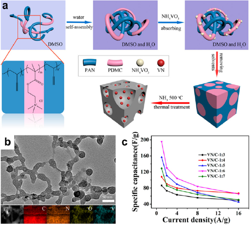
Figure 10. (a) Schematic illustration of the synthesis of VN-embedded porous carbons using PAN-b-PDMC-b-PAN. (b) A TEM image of VN-embedded porous carbons and the corresponding elemental maps of C, N, O, and V. (c) Rate capability of VN-embedded porous carbons with various mass ratios of VN to carbon. Testing condition: three-electrode system in 2 M aqueous KOH. Reproduced with permission from [101]. Copyright © 2018 American Chemical Society.
Download figure:
Standard image High-resolution imageDepositing functional materials on block copolymer-derived porous carbons represents an effective route toward composite electrodes. Recently, MnO2 was deposited on PAN-b-PMMA PCFs, and the resulting composite (PCF@MnO2) showed the highest gravimetric capacitance of 1148 F g−1 of MnO2, ~84% of the theoretical limit of MnO2. Pseudocapacitive MnO2 nanosheets were deposited in the mesopores of the PCFs via a solution-based redox reaction (figure 11(a)). After 2 h of deposition, MnO2 nanosheets were uniformly coated on the fiber surfaces (figure 11(b)), and the thickness of the MnO2 layer was ~2 nm. The thin MnO2 layer partially filled the mesopores as evidenced from the shift of the mesopore size from 11.7 nm to 9.3 nm (figure 11(c)). The partially filled and interconnected mesopores of PCF@MnO2 provided ultra-small ion diffusion resistivities, which were significantly smaller than the MnO2 electrodes prepared by other means (figure 11(d)). The overall gravimetric and areal capacitances of PCF@MnO2 outperformed the conventional MnO2-based composite electrodes at comparably high mass loadings (figure 11(e)). The PCFs derived from block copolymers highlight the advantages of enhancing the capacitances and reducing the ion diffusion resistance in composite electrodes, especially at high mass loadings of functional materials.
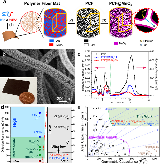
Figure 11. (a) Schematic illustration of the synthesis of PCF@MnO2. (1) Electrospinning of PAN-b-PMMA into fiber mats, followed by microphase separation into PAN (blue) and PMMA (red) domains. (2) Pyrolysis of PAN-b-PMMA fibers to decompose PMMA into uniform mesopores (white channels) and to convert PAN into a continuous carbon matrix (black). (3) Deposition of MnO2 into the mesopores of PCF via a solution-based redox reaction. The magnified view shows continuous carbons and mesopores for electron conduction and ion diffusion, respectively. (b) SEM image of PCF after depositing MnO2 for 2 h (PCF@MnO2-2 h). (Inset) A photograph of a piece of PCF@MnO2-2 h next to a U.S. penny. (c) The pore size distributions of PCF, PCF@MnO2-1 h and PCF@MnO2-2 h. The green dashed line marked the boundary between micropores and mesopores. (d) The ion-diffusion resistivities of PCF@MnO2 and other electrodes. CF: PAN-derived carbon fibers; CF@MnO2: MnO2-coated CFs. Data points marked with Roman numbers are cited from I: Jannasch [116], II: Mai et al [117], III: Zhang et al [118]. (e) Mass loadings, gravimetric capacitances and areal capacitances of PCF@MnO2 and other reported electrodes including I, MnO2 deposited on wood-derived porous carbon monolith [119]; II, hierarchical MnO2 on carbon cloth [120]; III, MnO2 on carbon nanotube (CNT) [121]; IV, MnO2-coated activated carbon/CNT [122]; V, MnO2-wrapped CNT/polyester fiber@MnO2 [123]; VI, MnO2 deposited on carbon nanofoam [124]. The solid and open dots are capacitances based on the mass loadings of entire electrodes and MnO2, respectively. Reproduced with permission from [125]. CC BY 4.0.
Download figure:
Standard image High-resolution imageDue to the electrically insulating nature, most block copolymers cannot be directly used as supercapacitor electrodes. Instead, they are useful electrode modification agents. For example, poly(acrylic acid)-block-poly(acrylonitrile)-block-poly(acrylic acid) (PAA-b-PAN-b-PAA) improves the hydrophilicity of activated carbon electrodes [126]. In PAA-b-PAN-b-PAA, PAN was incorporated into the activated carbon and PAA dangled on the carbon surface (figure 12(a)). After incorporating PAA-b-PAN-b-PAA, the activated carbon film became highly flexible (figure 12(b)). SEM showed that the surface layer (~30 µm in thickness) was more porous than the underlying layer (figure 12(c)). The surface layer was composed of activated carbon particles entangled with PAA-b-PAN-b-PAA, which helped the electrolyte completely wet the activated carbon. The hydrophilic PAA attracted cations and facilitated the formation of EDL on the electrode surface. The electrode displayed near-ideal capacitive behavior as evidenced by its quasi-rectangular cyclic voltammograms (CVs) at scan rates from 5 to 50 mV s−1 (figure 12(d)). The strategy of modifying electrode surfaces with block copolymers to improve the capacitance was later extended to other block copolymers including F127, PDMC-b-PAN-b-PDMC and PVP-b-PAN-b-PVP [127].
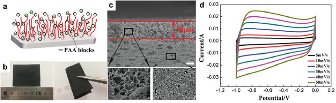
Figure 12. (a) Schematic illustration of an activated carbon supercapacitor electrode coated with PAA-b-PAN-b-PAA. (b) Digital photographs of a flat and a bent electrode. (c) Cross-sectional SEM images of the electrode. The red lines outline the boundaries of the block copolymer layer on the activated carbon. Scale bar, 1 µm. (d) CVs of the electrode in 2 M aqueous KOH at scan rates of 5–50 mV s−1. Reproduced from [126], with permission of The Royal Society of Chemistry.
Download figure:
Standard image High-resolution imageBlock copolymers containing electrically conductive and redox active blocks (e.g. polyaniline) can be directly used as supercapacitor electrodes. A tri-block copolymer hydrogel composed of a central PEO block and two polyaniline-capped poly(acrylamide) terminal blocks stored a large amount of charge (919 F g−1 at 0.5 A g−1) with good stability (90% capacitance retention after 1000 cycles) [128].
3.1.2. Block copolymer electrolytes.
Flexible, stretchable and wearable supercapacitors prefer solid or quasi-solid-state gel electrolytes. Compared to liquid-state electrolytes, the self-standing solid-state polymer electrolytes minimize the possibility of electrolyte leaking and simplify device fabrication. The ionic conductivity of polymer electrolytes originates from their ion solvation. PEO-containing block copolymers are the most used ion-conducting polymer electrolytes [129–131], because PEO is hydrophilic and it conducts ions. To maintain self-standing films, PEO is often copolymerized with mechanically robust polymers such as PPO [130], PMMA [132], PS [129, 132], and poly(styrene-co-divinylbenzene) [P(S-co-DVB)] [131]. The affinity of the polymer electrolytes to electrodes can be tuned by the chemistries and molecular weights of the conducting and non-conducting blocks [130].
Minimizing the contact resistances between polymer electrolytes and electrodes is a key to improve the electrochemical performance of supercapacitors with solid-state electrolytes. The contact resistance is associated with the difficulty in completely infiltrating the solid or highly viscous gel electrolytes into the porous electrodes. High contact resistance reduces the capacitances, rate capabilities and power densities of supercapacitors. A series of poloxamers (PEO-b-PPO-b-PEO) end capped with triethoxysilane groups significantly improved the infiltration of electrolytes in supercapacitors and minimized the contact resistances [130]. The triethoxysilane groups reduced the viscosity and allowed the electrolytes to easily permeate into the pores of the activated carbon/graphene electrodes (figure 13(a)). The subsequent solvent evaporation attached the chain ends of the block copolymers to the electrodes. The advantages of the block copolymer electrolytes are their ultrahigh ionic liquid uptake and more than one order of magnitude higher ionic conductivity than the conventional PEO electrolyte (figure 13(b)). A symmetric supercapacitor with the most ionically conductive PEO-b-PPO-b-PEO electrolyte exhibited the highest capacitance, as evidenced by the largest area enclosed by its CV curve (figure 13(c)). The device was also highly flexible and retained >93% of the capacitance after 5000 bending cycles (figure 13(d)).
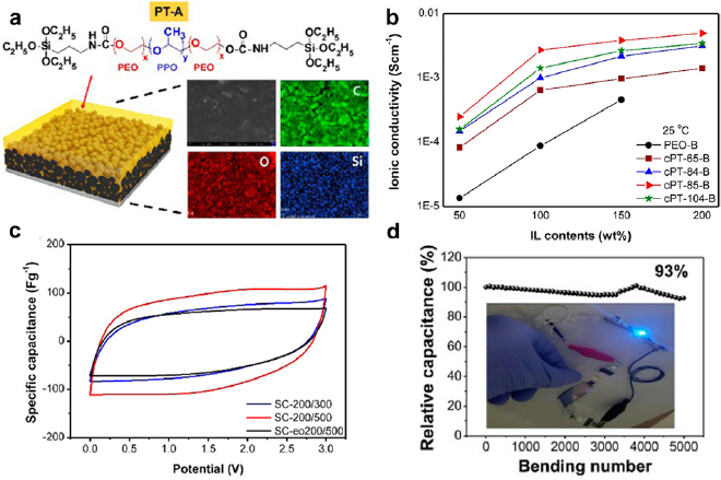
Figure 13. (a) Schematic illustration of a triethoxysilane end-capped PEO-b-PPO-b-PEO gel impregnated carbon/graphene electrode. The elemental maps prove the uniform infiltration of the block copolymer electrolyte. (b) Ionic conductivity versus ionic liquid (IL) contents of the polymer electrolytes. cPT-65-B, cPT-84-B, cPT-85-B, cPT-104-B are block copolymer electrolytes with molecular weights of 3.5, 4.2, 4.6, and 5.9 kDa, respectively. PEO-B has a molecular weight of 400 kDa and is used as the reference. The IL is 1-butyl-3-methylimidazolium tetrafluoroborate. (c) CVs of symmetric supercapacitors with the PEO-b-PPO-b-PEO (SC-200/300 and SC-200/500) and PEO polymer electrolytes (SC-eo200/500). The '200' in the designations means the weight percentages of the IL infiltrated in all electrodes are 200 wt%. The IL contents doped in the separators of the SC-200/300, SC-200/500 and SC-eo200/500 supercapacitors are 300 wt%, 500 wt% and 500 wt%, respectively. (d) The stability of SC-200/500 subjected to bending tests. The inset shows a blue light emitting diode powered by SC-200/500. Reproduced with permission from [130]. Copyright © 2017 The American Chemical Society.
Download figure:
Standard image High-resolution image3.2. Dielectric capacitors
Dielectric capacitors deliver intense voltage or current pulses that are essential for devices that require ultrahigh power start and acceleration, such as cardioverters, pacemakers, aircrafts, and military weapons. The critical component of a dielectric capacitor is a dielectric medium between two parallel electrically conductive substrates (figure 14). Electrical energy is stored in the dielectric media in the form of aligned dipoles induced by an external electric field.
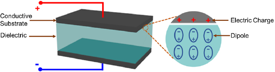
Figure 14. The structure of a parallel-plate dielectric capacitor that is composed of a dielectric separator sandwiched between two parallel electrically conductive substrates. The magnified view shows the formation of aligned dipoles in the dielectric media upon an external electric field.
Download figure:
Standard image High-resolution imageThe volumetric energy density (U, in J m−3) of a dielectric capacitor is determined by the strength of the applied electric field (E, in V m−1) and electric displacement (D, in C m−2). The latter is associated with the electric field strength and electric dipole moment density (D = ε0εrE):
For linear dielectrics (i.e. εr is independent of E), equation (10) can be simplified to:
According to the above equation, increasing either  or E will boost the volumetric energy density. One risk of increasing E, however, is the possibility of dielectric breakdown, i.e. the dielectrics become conductive and the two substrates are electrically short-circuited. Dielectric breakdown usually starts at defect sites and cascades to form fractal electron conductive pathways (i.e. electrical 'trees') within dielectrics. At the dielectric breakdown, the electrical trees reach both sides and electricity flows across the dielectrics. The maximal electric field and voltage that a dielectric withstands are termed breakdown strength and breakdown voltage, respectively.
Compared to ceramic dielectrics, polymer dielectrics are preferred in miniaturized electronics because of their processability into thin films without rupture. Additionally, polymer dielectrics have high breakdown strength (>7 MV cm−1) and are immune to minor breakdown (i.e. graceful failure). Most commercial polymer-based dielectric capacitors use bi-axial oriented poly(ethylene terephthalate) (BOPET). BOPET has a relatively low energy density (1.6 J cm−3) and thus tremendous efforts are dedicated to developing dielectrics with high energy densities. Block copolymers are promising next-generation dielectrics that can potentially offer energy densities superior to the commercial dielectric capacitors. Generally, there are two strategies to use block copolymers as dielectrics: (1) their direct use as dielectrics and (2) the indirect use as matrices in composite dielectrics to host guest dielectric fillers.
3.2.1. Block copolymers dielectrics.
The direct use of block copolymers as dielectrics has gained increasing interests due to its simplicity. However, most polymers cannot be readily polarized by an electric field, and hence they exhibit dielectric constants incomparable to ceramics. To enhance the dielectric constants of polymers, there are three main strategies:
- (1)Reinforce dipole polarity (electrical polarization) by introducing electron-rich groups or electron conjugated structures. Polar groups such as –F [133, 134], –CN [135], and sulfone [136, 137] substantially boost the degree of polarization, especially when the groups are aligned in the direction of the applied electric field. In addition, polymers with conjugated structures such as polythiophene [138], poly(isobutylene) [136], and poly(arylene ether ketone) [135] are also potent to improve the dielectric constant.
- (2)Improve the polarizability (ionic polarization) by introducing ionic clusters. The charged polymer units and the counterions form permanent dipoles that can be readily polarized by an electric field. These charged units increase the dielectric constant in a similar fashion to electrical polarization, except the polarization is induced by ion pairs rather than delocalized electrons.
- (3)Enhance the breakdown voltage (interfacial polarization) by creating conductive/insulating interfaces. Near the conductive/insulating interfaces, the space charge layers provide an electric-field shielding effect and prevent the growth of 'electric trees'. Lamellar block copolymers are ideal to construct the conductive/insulating layered structures.
Practically, the three strategies are often executed together to maximize the performance of dielectric capacitors. An example is two-stranded and ladder-shaped N-3,5-bis(trifluoromethyl)biphenyl-norbornene pyrrolidine (TNP)-based block copolymers (figure 15(a)) [139–141]. Three characteristics of this type of block copolymers are beneficial for dielectric capacitors. First, the C–F bonds and conjugated strand linkers impart electrical dipolar polarization. Second, the charged quaternary N and the surrounding counter ions provides ionic polarization. Third, the alternating conductive and insulating blocks induce interfacial polarization. Figure 15(b) presents a synthesis protocol for a TNP-based block copolymer dielectric. The TNP-based block copolymer displayed a high relative permittivity of 33 and an energy density of 9.95 J cm−3 at an electric field strength of 370 MV cm−1 [140]. In comparison, dielectric capacitors based on commercial biaxially oriented polypropylene (BOPP) dielectrics only stored 1.6 J cm−3 at 400 MV cm−1.
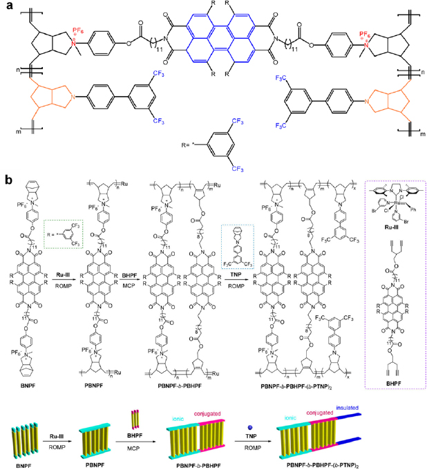
Figure 15. (a) The molecular structure of a two-stranded, ladder-shaped block copolymer. The colored regions are active regions that generate electrical polarization (blue), ionic polarization (red) and interfacial polarization (orange). (b) Synthesis of PBNPF-b-PBHPF and PBNPF-b-PBHPF-(b-PTNP)2 ladder-shaped block copolymers. BNPF: bis[(norbornene pyrrolidinium hexafluorophosphate)phenyl] perylene 2,3,6,7-tetra[bis(trifluoromethyl) phenyl] bisimide; BHPF: bis(4-methoxyl-1,6-heptadiyne) perylene 2,3,6,7-tetra[bis(trifluoromethyl) phenyl] bisimide; TNP: N-3,5-bis(trifluoromethyl)biphenyl-norbornene pyrrolidine; ROMP: ring-opening metathesis polymerization; MCP: metathesis cyclopolymerization; (b) reproduced with permission from [140]. Copyright © 2018, American Chemical Society.
Download figure:
Standard image High-resolution imageA lamellar PS-b-PMMA dielectric is an excellent example highlighting the advantage of insulating/conducting alternating structure [142]. PS with a dielectric constant of 2.6 served as the conducting phase, and PMMA with a dielectric constant of 3.2 was the insulating phase. An annealing technique termed cold zone annealing-soft shearing (CZA-SS) induced the self-assembly into lamellae parallel to the substrate (figures 16(a) and (b)). If treated with conventional oven-heating, the same block copolymer only evolved into randomly oriented lamellae. The CZA-SS annealed block copolymer dielectric achieved the highest energy density of 4.6 J cm−3 among all the tested polymers, which was ~2.25 and ~3.5 times higher than those of the as-cast and oven-heated films, respectively (figure 16(c)).
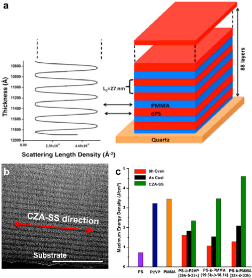
Figure 16. (a) The neutron reflectivity profile (left) and the corresponding structure (right) of PS-b-P2VP lamellae parallel to a quartz substrate. dPS is deuterated PS for enhanced neutron reflection. (b) A cross-section TEM image of PS-b-P2VP. The black layer at the bottom of the image is an Al-coated quartz substrate. PS and PMMA appeared dark and bright in the TEM image, respectively. CZA-SS: cold zone annealing-soft shearing. (c) Comparison of the maximum energy densities of PS (100 kDa), P2VP (77 kDa), and PMMA (88 kDa) hompolymers, as well as horizontally aligned (CZA-SS), vertically aligned (6 h Oven) and as cast (As Cast) block copolymers. Reproduced with permission from [142]. Copyright © 2016 American Chemical Society.
Download figure:
Standard image High-resolution image3.2.2. Block copolymer-based composite dielectrics.
Embedding ceramic particles in polymer matrices is an effective method for achieving high-energy-density dielectrics. The composite dielectrics combine the inherently high dielectric constants of ceramics and the excellent breakdown tolerance of polymers. However, because of the weak interactions between polymer matrices and ceramic particles, the embedded ceramic particles tend to aggregate. The particle aggregation increases the likelihood of forming continuous particle-polymer interfaces that become electron conduction pathways and substantially reduce the overall breakdown strength [143].
Surface modification of the particles with block copolymers is effective in addressing the challenge of filler dispersion, which is a common problem of polymer composites. For example, a grafted layer of PS-b-poly(styrene-co-vinylbenzylchloride) (PS-b-PSVBC) helped the uniform distribution of ceramic barium titanate (BaTiO3) nanoparticles, whose relative permittivity is ~7000 [143]. To graft PS-b-PSVBC onto BaTiO3, the nanoparticles were treated with ultraviolet-ozone radiation to generate negative charges on the surface. The chloromethyl groups of PSVBC reacted with BaTiO3 and the polymer chains were covalently attached to the particles. The chloromethyl groups were then converted to polar ammonium groups using triethylamine, and the block copolymer chains collapsed and formed a dense layer on the BaTiO3 particles (figure 17(a)). SEM showed a uniform polymer shell with a thickness of ~3 nm (figure 17(b)). The nonpolar PS chains improved the compatibility of block copolymer-coated BaTiO3 nanoparticles with the PS matrix, which assisted the uniform distribution of BaTiO3 in the composites. The BaTiO3/PS-b-PSVBC composites with 25 wt% BaTiO3 exhibited the smallest leaking current density of 0.38 nA cm−2 at an ultrahigh electric field of 0.2 MV cm−1 (figure 17(c)). The composites with 75 wt% BaTiO3 achieved the highest energy density of 9.7 J cm−3.
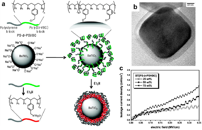
Figure 17. (a) The synthesis of PS-b-PSVBC/BaTiO3 nanoparticles for dielectric capacitors. (b) A TEM image of a BaTiO3 nanoparticle enclosed in a PS-b-PSVBC shell. (c) Leakage current density of PS-b-PSVBC/BaTiO3 with various BaTiO3 contents as a function of the electric field. Reproduced with permission from [143]. Copyright © 2010 American Chemical Society.
Download figure:
Standard image High-resolution image3.3. Rechargeable batteries
Rechargeable (or secondary) batteries are ubiquitous in electronics. Their energy densities are orders of magnitude higher than those of dielectric capacitors and supercapacitors. Since the first commercialization by Sony Corporation in 1992 [144], lithium-ion (Li-ion) batteries have gradually dominated the market of consumer electronics and have been adopted in electric vehicles recently. The charging and discharging of Li-ion batteries involve chemical reactions between Li+ and the electrode materials. In a charging process, driven by an external voltage bias, Li+ ions de-intercalate from a cathode, enter the electrolyte, migrate across a separator toward an anode, and eventually intercalate into the anode (figure 18(a)). Concomitantly, electrons flow from the cathode to the anode via an external electric circuit. In a discharging process, Li+ ions and electrons move in their respective reverse directions (figure 18(b)).
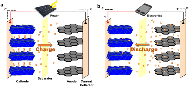
Figure 18. The (a) charging and (b) discharging processes of a Li-ion battery. The anode and cathode of commercial Li-ion batteries are typically made of graphite and lithium cobaltite, respectively. Current collectors are usually electrically conductive metal foils. A separator locates between the two electrodes to prevent electrical short circuit (i.e. electrons flow directly between the cathode and anode). Electrolytes (not shown) are filled between the two electrodes.
Download figure:
Standard image High-resolution imageDue to the length restiction, this topical review will not present an exhaustive overview of all the rechargeable batteries developed during the past decades. Interested readers are directed to detailed review articles on Li-air batteries [145], Li-S batteries [146], flow batteries [147], and alkaline-ion batteries [148].
3.3.1. Block copolymer electrodes and additives.
The selection of Li-ion battery electrode materials is determined by the charge-storage mechanism. Electrode materials that store charges via ion intercalation-deintercalation must possess ion-diffusion channels such as layered/tunneled structures (figure 18). Materials that form alloys or undergo conversion reactions with Li+ must maintain their structural integrity during the repeated charge–discharge cycles. Block copolymers have found uses in both types of electrodes.
Electrically conductive and redox active block copolymers can directly serve as battery electrodes. For example, 2,2,6,6-tetramethylpiperidinyl-N-oxyl (TEMPO) is redox active and can store charges via radical formation. Poly(TEMPO methacrylate)-block-polystyrene micelles with poly(TEMPO methacrylate) corona are potent cathode materials for flow batteries [149]. However, the direct use of block copolymers as battery electrodes remains in its infancy because most block copolymers are electrical insulating and inert to electron/ion storage.
Block copolymers are used as structure-directing agents or soft templates to create mesoporous battery electrodes with improved cycling stability. Peng et al recently synthesized two-dimensional zinc ferrite (ZnFe2O4) mesoporous sheets using F127 [150]. Electrochemical cycling stability test revealed that the cycling stability of the mesoporous sheets was much better than the nonporous ones. Operando TEM characterizations revealed that the improved stability was associated with the mesopores which effectively reduced the destruction imposed by the volume expansion upon lithiation. In addition to ZnFe2O4, F127 has also templated the synthesis of mesoporous NixCo3−xO4 [151], silica [152], TiNb2O7 [153] and bronze-phase TiO2 [154] cathodes.
Besides electrodes and templates, block copolymers also function as additives in battery electrodes. For example, vanadium pentoxide (V2O5) is a high-capacity cathode material with an energy density of 294 mAh g−1, but it has a low electrical conductivity and limited structural robustness. Combining V2O5 with block copolymer poly(3-hexylthiophene)-block-poly(ethylene oxide) (P3HT-b-PEO) mitigated the drawbacks of V2O5 [155]. P3HT was electrically conductive and thus alleviated the limited electrical conductivity of V2O5, while PEO prevented V2O5 nanosheets from severe re-stacking during the synthesis process. After the dispersion of P3HT-b-PEO micelles in water, a suspension of V2O5 nanosheets was added and the mixture was vacuum filtrated into V2O5/P3HT-b-PEO hybrid films (figure 19(a)). Electron microscopy showed that the block copolymer micelles were sandwiched between the V2O5 nanosheets. Thanks to the block copolymer, the stretchability of the electrodes drastically improved, as shown by the tensile profiles (figure 19(b)). In addition, the block copolymer enhanced the cycling stability. The neat V2O5 electrode without P3HT-b-PEO suffered from constant capacity degradation, while the hybrid electrodes with 5 wt% and 10 wt% of P3HT-b-PEO exhibited no appreciable capacity loss (figure 19(c)), due to the minimization of V2O5 pulverization during charging and discharging by the soft P3HT-b-PEO buffer fillers.

Figure 19. (a) The preparation procedure of a composite hybrid electrode by vacuum filtering a solution containing V2O5 nanowires and P3HT-b-PEO block copolymers. (b) Representative tensile curves and (c) discharge capacity stability and coulombic efficiency of neat V2O5 and composite hybrid electrodes. The two hybrid electrodes P5 and P10 have 5 wt% and 10 wt% of P3HT-b-PEO, respectively. Reproduced with permission from [155]. CC BY 4.0.
Download figure:
Standard image High-resolution image3.3.2. Block copolymer-derived carbon electrodes.
Similar to supercapacitor electrodes, block copolymers are pyrolyzed into nanostructured carbons and used as battery electrodes. An excellent example is oxygen-anchored carbon nanosheets converted from F127 mixed with sodium chloride (figure 20(a)) [156]. These carbon sheets (figure 20(b)) with graphitized regions (figure 20(c)) allowed for rapid Li-ion intercalation. The capacity reached ~600 mAh g−1 at 1 A g−1 and only experienced marginal loss, as the current density was increased from 1 to 20 A g−1 (figure 20(d)). The outstanding rate capability was ascribed to the interlayer oxygen atoms that widened the interlayer gap and reduced the steric hindrance for Li+ intercalation and de-intercalation.
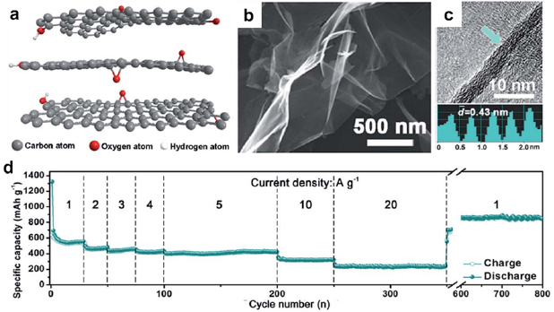
Figure 20. (a) Molecular structure, (b) SEM and (c) TEM images of the F127-derived carbon nanosheets. The bottom of (c) shows the interlayer distance of a graphitized region (highlighted by the green arrow). (d) Rate capability of F127-derived carbon nanosheets. Reproduced from [156] with permission of The Royal Society of Chemistry.
Download figure:
Standard image High-resolution imageThe block copolymer-derived carbon nanostructures are versatile substrates for a wide range of functional materials in composite electrodes. High-capacity functional materials usually suffer from high electrical resistance and poor cycling stability, and thus they are integrated with conductive carbons to address their shortcomings. For example, sulfur [157–160], NiO [161], and Nb2O5 [162] are representative functional materials coupled with block copolymer-derived carbons. The incorporation of the functional materials is achieved by either conversion of preloaded precursors or direct post-infiltration into mesoporous carbons.
C/S hybrid electrodes for Li-S batteries are examples of the block copolymer-based composite battery electrodes. Li-S batteries are promising rechargeable batteries with a high specific energy density of ~500 Wh kg−1, in comparison to Li-ion batteries with energy densities of 150–250 Wh kg−1. However, the development of Li-S batteries is greatly hindered by the drawbacks of sulfur: the electrically insulating nature, the charge/discharge-induced structural instability, and the polysulfide shuttling effect [163]. All these drawbacks significantly shorten the lifespan of Li-S batteries. In 2009, Nazar and coworkers reported for the first time that ordered mesoporous carbon CMK-3 was a suitable scaffold for S to relieve these problems [163]. Thereafter, a number of C/S composite electrodes with superior performances originated from block copolymers have been demonstrated [157, 159, 164]. One notable example is a 3D Li-S nano-battery assembled from a gyroid carbon matrix [157]. The gyroid carbon matrix was obtained by the pyrolysis of poly(isoprene)-block-poly(styrene)-block-poly(ethylene oxide) (PIO-b-PS-b-PEO) infiltrated with phenol-formaldehyde (PF) resol. The as-formed gyroid carbon matrix was sequentially coated with PPO electrolyte and poly-(3,4-ethylenedioxythiophene)-blended S cathode. A 3D nano-battery was assembled by connecting the carbon matrix with a piece of Li metal and submerging in a Li+-containing organic electrolyte (figure 21(a)). SEM confirmed the uniformly filled PPO and S in the cavities of the gyroid carbon network (figures 21(b) and (c)). The 3D nano-battery exhibited a wide voltage plateau at 1.4 V versus Li+/Li and an areal capacity of ~7.5 mAh cm−2 (figure 21(d)). The most important merit of the nano-battery is the nanoscale gaps between the cathode and the anode, which decreased the Li+ diffusion distance and augmented the charge-storage capacity at high rates.
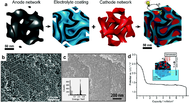
Figure 21. (a) Sequential assembly of a 3D gyroidal nano-battery using a double gyroidal mesoporous carbon monoliths derived from PIO-b-PS-b-PEO and oligomeric phenol-formaldehyde resols. Black: carbon (anode); blue: PPO (polymer electrolyte and separator); red: sulfur blended with poly(3,4-ethylenedioxythiophene) (cathode). SEM images of (b) a gyroidal carbon network and (c) an assembled 3D nano-battery. (Inset of (c)) EDS spectrum of the shown region. (d) The potential-capacity profile of the gyroid nanohybrid upon lithiation using an external lithium source (current density: 0.125 mA cm−2). Reproduced from [157] with permission of The Royal Society of Chemistry.
Download figure:
Standard image High-resolution image3.3.3. Block copolymer solid-state electrolytes.
In the last decade, we have witnessed steady improvements in energy density and output voltage of batteries, thanks to the development of new electrodes and diverse batteries (e.g. Li-S [146], Li-air [145], Na-ion batteries [148]). However, safety becomes an increasingly concern as the energy density continues to increase. In case of overcharging or poor thermal management, the highly flammable liquid electrolytes could ignite and cause battery combustion and even explosion. Chemically stable, non-flammable and solid-state electrolytes are highly desirable to improve the safety and minimize electrolyte leaking.
The mutual exclusiveness of high ionic conductivity and structural robustness is a long-lasting challenge for conventional PEO-based solid-state electrolytes. The ion transport in PEO relies on the chain flexibility in the amorphous regions [165–167]. The crystalline regions, however, have a melting point (Tm) of ~65 °C which greatly reduces the room-temperature ion conductivity to the magnitude of ~10−5 S cm−1 (see table 1 of [165]). The conductivity increases at temperatures above Tm but at the cost of reduced structural integrity. Additionally, because salts elevate the glass transition temperature (Tg) of PEO, the ionic conductivity of PEO at room temperature decreases appreciably as the salt concentration increases [31].
PEO-containing block copolymers circumvent the drawbacks of pure PEO by decoupling ionic conductivity and mechanical strength. The PEO block solvates with lithium salts, such as lithium bis(trifluoromethanesulfonyl)imide (LiTFSI) and lithium triflate (LiSO3CF3), and are responsible for ion conduction. The rest blocks provide structural robustness [168–183]. The structure-supporting blocks are typically made of Jeffamine (a comb polymer containing polyether chains) [184], poly[2-(2-(2-methoxyethoxy)ethoxy)ethyl glycidyl ether] [185], and poly(1-((2-acryloyloxy)ethyl)-3-butylimidazolium bis(trifluoromethanesulfonyl)imide) [186].
In addition to the copolymerization with mechanically strong blocks, the use of guest particles is another strategy to reinforce the structure integrity of electrolytes. In addition, the guest particles hinder the crystallization of PEO and improve its ionic conductivity. Example particles include titanium dioxide (TiO2) [187] and poly(styrene trifluoromethanesulphonylimide of lithium)-grafted polyhedral oligomeric silsesquioxane (POSS) [188].
Block copolymers can also function as a group of unique solid-state electrolytes termed 'single-ion electrolytes'. In single-ion electrolytes, either cations or anions are mobile, while both cations and anions are movable in dual-ion electrolytes. For example, in PEO-based dual-ion electrolytes, metal cations (e.g. Li+) coordinate strongly with the EO units but anions only interact weakly with them [189]. The different interaction strengths result in an impeded Li+ conduction but a dominating anion conduction, that is, ~80% of the total charges are carried by the anions under an external bias [190]. In dual-ion PEO-based electrolytes, the different ion flow rates induce an anion concentration gradient in the electrolytes, lower the battery capacity, and cause the formation of Li dendrites. In contrast, in Li+-conducting single-ion electrolytes, anions are covalently tethered to the polymer chains, and thus their long-range motion is prohibited. The immobilized anions diminish the concentration polarization and improve the battery performance [191].
Single-ion block copolymer electrolytes typically contain blocks with negatively charged functional groups, which are linked with structure-reinforcing blocks [192, 193]. These negatively charged polymer blocks are often based on imide [42, 59, 190, 194, 195], carboxylate [58, 172, 173, 196], borate [192, 193], and sulfonate [181, 194, 197].
For example, in a linear P(STFSILi)-b-PEO-b-P(STFSILi) tri-block copolymer, where P(STFSILi) is poly(styrene trifluoromethanesulphonylimide of lithium [190], the central PEO block served as the Li+ conduction channel, and the peripheral P(STFSILi) blocks contained the immobile anions of negatively charged sulphonylimide groups (figure 22(a)). Regardless of the weight percentages of STFSILi, the ionic conductivities of the electrolytes increased from 45 °C to 90 °C (figure 22(b)). The electrolyte that contained 20 wt% P(STFSILi), corresponding to an EO/Li+ molar ratio of ~30, achieved the highest ionic conductivity of 1.3 × 10⁻⁵ S cm−1 at 60 °C (figure 22(b) inset). This conductivity was about an order of magnitude higher than that of the pure PEO electrolyte with similar EO/Li+ ratios. The tensile strength of the P(STFSILi)-b-PEO-b-P(STFSILi) single-ion electrolyte was substantially higher than that of PS-b-PEO-b-PS (SEO) dual-ion electrolytes (figure 22(c)). The improved mechanical strength was ascribed to the ionic coupling between the negatively charged P(STFSILi) blocks and the Li+-impregnated PEO central block. Electrochemically, the single-ion electrolyte exhibited a stable potential window of 5 V (figure 22(d)), which was much larger than the nominal ~4 V window of most Li-ion batteries. The electrolyte also showed better rate capability at 80 °C than a previously reported ZrO2-PEO composite electrolyte [198] (figure 22(e)).
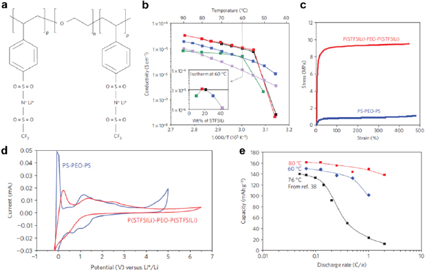
Figure 22. (a) The chemical structure of a single-ion triblock copolymer P(STFSILi)-b-PEO-b-P(STFSILi) as solid-state electrolyte. (b) Arrhenius plots of ionic conductivity with temperature. (Inset) Ionic conductivities of P(STFSILi)-b-PEO-b-P(STFSILi) with various weight percentages of STFSILi at 60 °C. Each color corresponds to a weight percentage of STFSILi. (c) Tensile curves of P(STFSILi)-b-PEO-b-P(STFSILi) and PS-b-PEO-b-PS. (d) CVs at 1 mV s−1 for a model battery composed of a lithium metal anode, a carbon-coated lithium iron phosphate (LiFePO4) cathode, and P(STFSILi)-b-PEO-b-P(STFSILi) electrolyte (31 wt% P(STFSILi), red curve) at 80 °C. Compared to the PS-b-PEO-b-PS electrolyte (30 wt% PS, blue curve), P(STFSILi)-b-PEO-b-P(STFSILi) (red curve) exhibited a broader electrochemically stable potential window. (e) The model Li-metal battery capacity as a function of the discharge rate at temperatures of 60, 76 and 80 °C. The data at 76 °C are based on a ZrO2-PEO composite solid-state electrolyte and adapted from [198]. Reproduced with permission from [190]. © 2013 Macmillan Publishers Limited. All rights reserved.
Download figure:
Standard image High-resolution image3.3.4. Block copolymer binders.
In batteries, binders bundle powder and particulate electrode materials and firmly fix them onto current collectors. The binders are also crucial for stabilizing the electrode materials that undergo large volumetric changes (e.g. Si, Sn, and S). Conventional polyvinylidene fluoride (PVdF) binder has the shortcomings of inelasticity and gradual volume swell in organic electrolytes, which shorten battery lifetime. In addition, PVdF is prone to self-aggregation that induces a substantial interfacial resistance.
The drawbacks of PVDF have stimulated the design and synthesis of block copolymer-based alternatives. Most block copolymer binders have a common ionically conductive PEO block impregnated with salts [199–202]. The other block(s) can be diverse. Mechanically strong polyimide [202–204], polydopamine [200], polybutylene [205], and PS [206] provide binders with ultrahigh strength and excellent flexibility, which are required to maintain battery durability. Electrically conductive poly(3-hexylthiophene) (P3HT) offers electrical conductivity and eliminates the need for conductive carbon black to serve as conductive additives. For example, P3HT-b-PEO could disperse much more uniformly in V2O5 nanosheets than a P3HT/PEO polymer blend [199]. Because PEO adhered more strongly to V2O5 than P3HT, PEO was well mixed with V2O5 but P3HT aggregated locally if the two polymers were simply blended together. The aggregated P3HT could not efficiently transport electrons and hence severely limited the performance. On the contrary, the use of P3HT-b-PEO binder mitigated the aggregation problem of P3HT, because the covalent link between P3HT and PEO forced the uniform dispersion of P3HT along with PEO. As a result, the block copolymer bound V2O5 electrode showed a much higher capacity than that of the polymer blend bound V2O5 or the neat V2O5 nanosheets without any binders (figure 23).
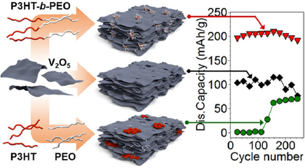
Figure 23. P3HT-b-PEO used as a binder for V2O5 nanosheets in Li-ion battery cathodes. The electrode with the di-block copolymer binder (top) shows higher capacities and stability than the binder-free electrode (middle) and the electrode with homopolymer blend binder (bottom). Reproduced with permission from [199]. Copyright © 2016 American Chemical Society.
Download figure:
Standard image High-resolution image3.3.5. Block copolymer separators.
Separators are important to prevent electric short circuits between the cathode and anode, especially in contemporary miniaturized batteries whose electrodes are extremely close to each other. To allow for fast ion diffusion, the separators must have low ionic resistances. Most separators contain a large number of macropores and mesopores that facilitate ion conduction, except for Li-air batteries, whose separators must be void-free to prevent air permeation [207]).
With the capability of self-assembling into porous structures, block copolymers are attractive materials for battery separators. An excellent example is a hierarchical porous Li-ion battery separator derived from PS-b-P4VP [208]. This separator was prepared by grafting 3-glycidoxypropyl-trimethylsilane (GPTMS) groups onto P4VP to increase the segregation strength between PS and P4VP (figure 24(a)). The GPTMS modified PS-b-P4VP was solution-cast into thin films and submerged in ethanol. The poor solubility of the block copolymer in ethanol resulted in non-solvent-induced phase separation which produced macropores. Meanwhile, the microphase separation of the two blocks created mesopores (figure 24(b)), leading to a hierarchical porous structure with P4VP on the surface (figure 24(c)). The hierarchical porous structure was beneficial for fast ion conduction, which reduced the battery internal resistance and minimized the separator-induced concentration polarization between the electrodes. The discharge capacity of a battery equipped with the PS-b-P4VP based separator outperformed that of a similar battery with a conventional polyolefin-based separator (figure 24(d)). The non-solvent-induced phase separation was also useful for the synthesis of porous poly(styrene-b-butadiene-b-styrene) membranes. The membranes were highly stretchable (~270% strain) and functioned as separators in flexible Li-ion batteries [209].

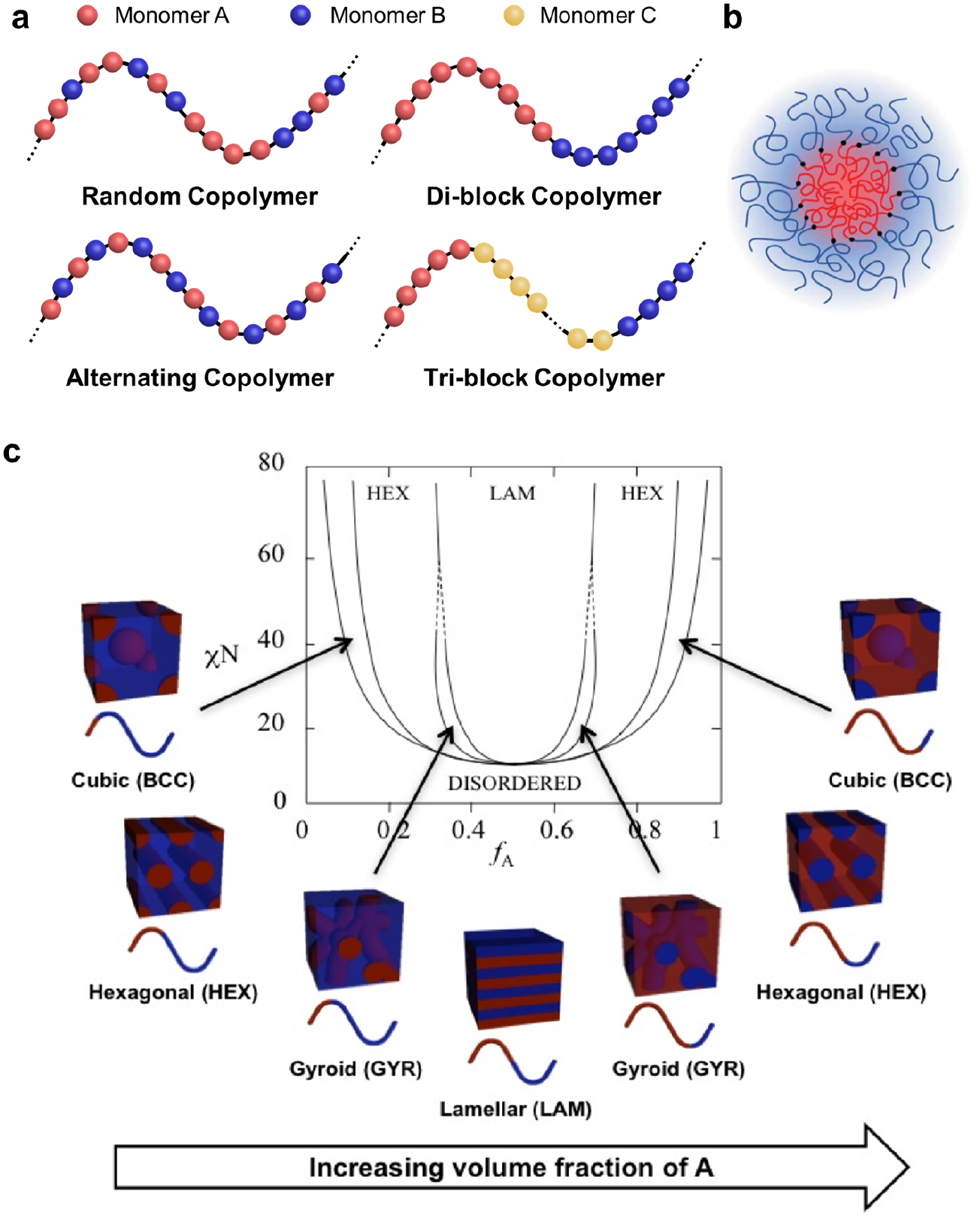
Figure 24. (a) The synthesis of crosslinked PS-b-G-P4VP web as a battery separator. GPTMS: 3-glycidoxypropyl-trimethylsilane. (b) A photograph of a piece of twisted PS-b-G-P4VP separator. The schematics present its hierarchical porous micro-structure. (c) A SEM image of the non-solvent-induced hierarchical porous architecture after self-assembly. (d) The cycling stability of hierarchical porous PS-b-G-P4VP separator (HMH-BCP) in comparison with a conventional polyolefin separator (PP/PE/PP) in Li-ion batteries. Reproduced with permission from [208]. CC BY 4.0. Copyright © 2015, The Author.
Download figure:
Standard image High-resolution image
Block copolymers are also used as ion exchange membranes in flow batteries. Flow batteries are a family of rechargeable batteries whose two electrodes are liquid ionized reactants [210]. The power output of a flow battery depends on the reactant concentration difference in the anode and cathode chambers. Any cross-mixing of the reactants is detrimental and must be strictly prohibited. Therefore, ion-exchange separators must physically segregate the ionized reactants but allow inert ions (e.g. protons) to flow through. So far, the preparation of block copolymer-based ion-exchange separators is similar to that of conventional porous membranes, except that it involves an additional step of anchoring functional groups onto the pore inner walls to impart ion-exchange capability. Example functional groups are sulfone [211, 212] for cation exchange and quaternary nitrogen [213, 214] for anion exchange.
4. Summary and outlook
In this topical review, we summarize the fundamental understandings of the block copolymer composition, morphology, and thermodynamics, as well as their effects on the pore size and ionic conductivity. Additionally, we present the state of the art of block copolymers in three types of energy storage devices: supercapacitors, dielectric capacitors, and batteries. To inspire future studies, we highlight the potential opportunities and pertaining challenges as follows.
In general, it is of crucial importance to synergistically integrate block copolymers into the energy storage field. As elaborated in section 2, previous studies have extensively examined the interplays among the block copolymer microphase-separation, pore size, and ionic conductivity. These studies will be beneficial if they are extended to the performance metrics of energy-storage devices, such as capacitance, capacity, rate capability, power density, and energy density.
The diverse and tunable morphologies of block copolymers provide a versatile platform for fundamental studies on the correlations between polymer structures and energy-storage performances. For example, ordered and tunable mesopores derived from block copolymer hexagonal structures are suitable for unveiling how the mesopore size affects the capacitance, rate capability, power density, and energy density. Nanostructures with bicontinuous networks are useful to reveal the influences of the pore tortuosity and interconnectivity on the rate capability and power density.
In addition, block copolymers have great potential to miniaturize the energy storage devices. The sizes of the conventional macroscale electrode/separator/electrode can be significantly reduced by block copolymers. An encouraging example is the nanobattery assembled from a gyroid triblock copolymer (figure 21) [157]. Due to the large surface area and ultra-small ion diffusion distance, block copolymer-based energy storage devices could potentially surpass their macroscale counterparts in terms of energy density, rate capability and power density. However, the fabrication of miniaturized energy storage devices is not trivial, and numerous challenges still remain. First, scalable synthesis of block copolymers with well-defined morphologies is challenging. To date, block copolymer-based energy storage devices focus on the gyroid phase, which has a small window in the block copolymer phase diagram and thus is not easy to target. Alternative structures are strongly desired. Second, the fabrication process must be handled meticulously to prevent electric short circuits. Third, upon addition of salt, the block copolymer phase behavior deviates from the neat block copolymers [215–219]. The deviated morphologies and their properties must be further understood.
The recent advancement in manufacturing techniques (e.g. 3D printing) has provided new avenues for applying block copolymers in energy storage. 3D printing has emerged as a powerful tool to build supercapacitor electrodes with ordered macropores [220] or to directly construct Li-ion batteries with interdigitated electrodes [221–224]. The 3D-printed arrays of macropores and the interdigitated structures facilitate the ion diffusion and markedly boost the rate capability [220]. Additionally, combining block copolymer with 3D printing allows for the design of hierarchical porous electrodes that possess uniformly distributed and highly interconnected pores at multiple length scales. These electrodes are expected to embrace ultrahigh surface areas and non-tortuous ion/electron transport channels, which bestow outstanding charge-storage performances. Besides 3D printing, in situ or operando probing techniques have been recently adopted in fundamental studies of energy storage [225, 226], which provide unprecedented opportunities to study the external bias-induced ion partition kinetics and the morphology evolution of block copolymer electrolytes. The synergistically integrated block copolymers in the field of energy storage are expected to offer significant breakthroughs in the foreseeable future.
Acknowledgments
This material is based upon work supported by the Air Force Office of Scientific Research under award number FA9550-17-1-0112, the National Science Foundation under Grant No. DMR-1752611, and the American Chemical Society Petroleum Research Foundation Doctoral New Investigator Award.