

Abstract
The generation of dynamic high energy density plasmas in the pico- to nano-second time domain at high-energy laser facilities affords unprecedented nuclear science research possibilities. At the National Ignition Facility (NIF), the primary goal of inertial confinement fusion research has led to the synergistic development of a unique high brightness neutron source, sophisticated nuclear diagnostic instrumentation, and versatile experimental platforms. These novel experimental capabilities provide a new path to investigate nuclear processes and structural effects in the time, mass and energy density domains relevant to astrophysical phenomena in a unique terrestrial environment. Some immediate applications include neutron capture cross-section evaluation, fission fragment production, and ion energy loss measurement in electron-degenerate plasmas. More generally, the NIF conditions provide a singular environment to investigate the interplay of atomic and nuclear processes such as plasma screening effects upon thermonuclear reactivity. Achieving enhanced understanding of many of these effects will also significantly advance fusion energy research and challenge existing theoretical models.
Export citation and abstract BibTeX RIS
Corrections were made to this article on 19 September 2019. In the review article the author list has been amended to include David Fittinghoff. Dr. Fittinghoff is a senior member of the diagnostic team at the National Ignition Facility. He contributed significantly to the implementation of the neutron imaging system which he documented in this review article. The other authors regret this oversight.
Glossary
| AZURE | An R-matrix code for nuclear astrophysics |
| CCD | Charge coupled device |
| CH | Carbon hydride (polystyrene) |
| COULEX | Coulomb excitation |
| CR-39 | Columbia Resin #39 (plastic polymer) |
| CVD | Carbon vapor deposition |
| DIM | Diagnostic instruments manipulator |
| DSR | Down scattered ratio (neutrons) |
| ELI | European Laser Institute |
| ENDF | Evaluated nuclear data file |
| ENDL | Evaluated nuclear data library |
| FAIR | Facility for AntiProton and Ion Research |
| FEL | Free electron laser |
| (F)NAD | (Flange) neutron activation diagnostic |
| FRIB | Facility for Radioactive Ion Beams |
| FWHM | Full width at half maximum |
| GCD | Gas Cherenkov detector |
| GEMS | Gamma-to-electron magnetic spectrometer |
| GRH | Gamma reaction history |
| HDC | High density carbon |
| HYDRA | ICF radiation-hydrodynamics code |
| ICF | Inertial confinement fusion |
| IRF | Instrument response function |
| LENS | Low energy neutron spectrometer |
| LLE | Laboratory for Laser Energetics |
| LOS | Line of sight |
| MagPTOF | Magnetic particle time of flight |
| MCNP | Monte-Carlo N-Particle Transport Code System |
| NACRE | Nuclear astrophysics compilation of reactions |
| NEEC | Nuclear excitation by electron capture |
| (N) HEDP | (Nuclear) high energy density plasma |
| NIF | National Ignition Facility |
| NIS | Neutron imaging system |
| NPI | Nuclear–plasma interactions |
| nTOF | neutron time of flight |
| OMEGA | (ICF laser system at LLE) |
| PD | Photo-diode |
| PMT | Photo-multiplier tube |
| RAGS | Radiochemical Analysis of Gaseous Species |
| RC | Radio chemistry |
| REC | Radiative electron capture |
| SED | Single event detector |
| SEF | Stellar enhancement factor |
| SRC | Solid radiochemistry collector |
| TANDM | Target and diagnostic manipulator |
| TCC | Target Chamber Center |
| WRF | Wedge range filter |
1. Overview of the NIF nuclear HEDP environment
1.1. Nuclear processes in dynamic HEDP
A novel laser based ICF facility, the NIF at Lawrence Livermore National Laboratory, is currently operational with the goal of achieving ignition and controlled thermonuclear burn in a laboratory environment [1].
The approach to ignition being pursued at NIF involves an indirect drive configuration where a series of a high-energy (>MJ), ns-long laser pulses are used to heat the interior surface of a cylindrical 'hohlraum' enclosure to temperatures more than 3.5 million K. The resulting intense flux of x-ray (Eγ ≤ 300 eV) photons ablates the surface of a mm-sized spherical fusion target in the center of the hohlraum. The target interior contains a solid cryogenic deuterium–tritium (DT) fuel layer surrounding a central low-density gaseous zone. The reaction force resulting from the ablation of the exterior of the capsule compresses the remaining capsule and DT fuel by a factor of 20–40, thereby heating the central hot spot to densities more than 10 g cm−3 (with the DT 'cold' fuel assembly at densities in excess of 1000 g cm−3), temperatures from 10 to 100 million K (kT ≈ 1–10 keV), and Gbar pressures. At peak compression, a portion of the DT fuel undergoes the D(T, n) α thermonuclear reaction, producing up to 1016 neutrons over a burn time of about 100 ps. In addition to these high-radial convergence cryogenic systems, NIF can field 'exploding pusher' capsules where a concentric shock-wave produces a hotter (kT ≈ 10–20 keV) lower density plasma with a lower overall neutron yield (1012–14) and extremely well characterized plasma conditions.
The resulting NHEDP environment is unique on earth, with fluxes of neutrons, photons and charged particles exceeding 1026, 1032 and 1036 cm−2 s−1 respectively during peak burn. The NIF NHEDP allows the study of the nuclear reactions responsible for the formation of the elements in astrophysical plasmas for the first time. The achievable plasma conditions are summarized in figure 1.

Figure 1. Schematic of the plasma conditions present in a compressed NIF capsule.
Download figure:
Standard image High-resolution imageThe relevance to astrophysical research arises in part from the fact that nuclei are small (and have small cross sections) and that nuclear states are narrow (1 fs ≈ 1 eV) and long-lived isomeric transitions are even narrower leading to only a very small portion of the plasma quanta (photons and electrons) in the plasma having the correct energy to interact with the nucleus. Thermonuclear and neutron-induced reaction rates and nuclear processes have been explored traditionally by means of conventional accelerator experiments, which are difficult to execute at conditions relevant to stellar nucleo-synthesis (SN) and big-bang nucleo-synthesis (BBN). Furthermore, even when accelerator-based measurements at relevant energies are possible, thermonuclear reaction rates in stars and BBN are inherently different from those in accelerator experiments. In accelerator experiments the fusing nuclei are surrounded by bound electrons, whereas electrons occupy mainly continuum states (degenerated) in a stellar environment and in HED plasmas leading to screening enhancements that need to be corrected for [2]. Developing an HED platform that uses new as well as the existing diagnostic capabilities discussed in this paper advances the frontiers of laboratory nuclear astrophysics into a new realm. Similarly, neutron-induced reactions in plasmas can potentially differ from those measured in an accelerator laboratory due to the potential thermal population of low-lying excited states, which have a different propensity to emit neutrons due to angular momentum differences. Of course, it should be emphasized that conducting nuclear astrophysics-relevant experiments at a facility like the NIF requires a careful assessment of the achievable accuracy and evaluation whether they can be done more efficiently elsewhere.
Astrophysical nucleo-synthesis reactions can broadly be divided into two categories: charged-particle induced and neutron-capture induced. In the case of charged particle reactions, the low energies (temperatures), over which these reactions take place lead to extremely low rates, which are difficult to reproduce at present accelerator facilities with an experiment of reasonable duration. The latter restriction is due to the Coulomb barrier that introduces an exponential sensitivity to the atomic number of the reactants:

where σ(E) is the energy-dependent reaction cross section, E is the energy, S(E) is the astrophysical factor, Z1 and Z2 are the charges of the two reactants, and e is the elementary charge.
In accelerator-based experiments using charged particle beams the reaction rate is then given by the product of this cross section, the beam current, and the areal density of the target:

In practice this rate is limited by the short range of the charged-particle beam due to electronic stopping. In contrast, the high compression of both the 'target' and the 'beam' reactants in a NIF capsule leads to a dramatic increase in the effective target areal density for both, resulting in a reaction rate 'boost' for a binary reaction rate of the reciprocal of the fourth power of the radial convergence, e.g., nearly 106 for a factor of 30 compression. Accelerator-based measurements of nucleo-synthesis charged particle reaction rates, taking place in solid matter or neutral gaseous targets, are affected by atomic screening. This can lead to a significant modification of the reaction rate relative to what it would be in a stellar plasma where reactants are completely or highly ionized. The plasma screening that these reactions experience due to the free electron cloud in a NIF capsule is far more like the conditions found in the astrophysical sites, where they take place. The theoretical treatment of screening conditions relies on assuming the applicability of the Debye–Hückel formalism, which has not been tested experimentally [3]. NIF provides a unique opportunity to perform such tests in a wide range of plasma conditions.
The very nature of the NIF implosion requires an accurate diagnosis and analysis of the time-dependent plasma conditions (e.g. temperatures, densities, anisotropies, and gradients). This requirement stems from the exponential sensitivity of charged particle reaction cross sections to the temperature arising from the Coulomb barriers between the reactants in the equation above. Less-convergent exploding pusher capsule designs minimize anisotropies, but result in lower overall reaction rates due to reduced areal densities. It is crucial to carefully evaluate (e.g. through simulations) the target configuration. It should be noted that if a specific reaction rate (i.e. its S(E)-factor) is well known, charged-particle reactions can be used to provide a sensitive diagnosis for the plasma parameters such as the ion temperature, thereby offering the possibility of performing more accurate measurements of reaction rate ratios.
As a practical matter, astrophysical neutron capture nucleo-synthesis experiments at NIF can potentially co-exist with neutron-producing ignition experiments. Various neutron producing reactions and scattering determine the neutron energy flux spectra as summarized in table 1. In addition, since neutron-induced reactions have no Coulomb barrier, they have a significantly decreased sensitivity on any spatial anisotropy in the temperature and density of the NHEDP. Lastly, the high neutron fluence in even a single NIF shot (≥1020 neutrons cm−2) is much higher than the integrated fluence current that can be achieved with accelerator-driven neutron sources.
Table 1. Neutron producing reactions in DD, TT and DT fusion reactions.
| Primary DT neutrons: | D + T → α (3.5 MeV) + n (14.1 MeV) + γ (16.8 MeV, γ/n ≈ 3 × 10⁻⁵) |
| Secondary neutrons from 14.1 MeV neutrons scattered elastically in the fuel: | n + D → n' (1.6–14.1 MeV) + D' (0–12.5 MeV) |
| n + T → n' (3.5–14.1 MeV) + T' (0–10.6 MeV) | |
| Tertiary, in-flight fusion reaction: | D' (0–12.5 MeV) + T → α + n'' (12–30.1 MeV) |
| T' (0–10.6 MeV) + D → α + n'' (9.2–28.2 MeV) | |
| (The yield of tertiary neutrons is proportional to ρR2) | |
| Additional reactions with primary and residual ions: | D + D → 3He + n(2.45 MeV), |
| D + D → p + T (1.01 MeV) | |
| D + T → 4He + n (11.8–17.1) | |
| D + 3He → α + 14.1 MeV p (+g) | |
| T + T → 4He + 2n | |
| Additional reactions with primary and residual ions: | α + D → α' + D'' (>14 MeV) |
| α + T → α' + T'' (>14 MeV) | |
| D'' + T'' → α + n'' (15–20 MeV) | |
Only reactors have similar run-integrated neutron fluences (≥1019 neutrons cm−2 per day) and the overwhelming majority of these neutrons tend to be at room-thermal (meV) rather than stellar-thermal (keV) energies.
The neutrons produced in a high yield NIF shot arise predominantly from the T (D, n) α reaction and are born with an initial energy of 14.1 MeV, which is dramatically different from the 10's of keV neutron spectrum found in the interiors of massive stars where heavy elements are formed through (n, γ) reactions [4]. These NIF neutrons need to be moderated to stellar thermal energies for them to be of value for a NIF-based nucleosynthesis experiment. Moderation requires multiple scattering off the low-mass DT fuel, which in turn requires that the assembled fuel maintains a high areal density (ρR)fuel for several 100 ps. Fortunately, a requirement for ignition is that the assembled DT fuel achieves a (ρR)fuel > 1 g cm−2 in order to ensure that the 3.54 MeV α-particle produced deposits its energy in the assembled fuel, and (ρR)fuel > 1 g cm−2 are now being regularly achieved in the indirectly driven capsules [5]. Advanced hydrodynamic simulations of capsule implosions resulting in these high peak (ρR)fuel values show that a significant portion of the primary neutrons are indeed scattered down to astrophysical-like energies, resulting in neutron capture rates similar to those for neutron-driven SN (see figure 2).
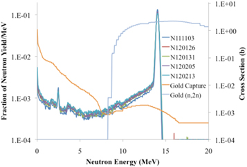
Figure 2. Shows post-shot simulated neutron spectra for DT ICF shots at the NIF. The simulations are produced using a HYDRA code package together with the 197Au (n, γ) and the 197Au(n, 2n) cross sections from ENDL. Approximately 30% of the primary 14.1 MeV neutrons scatter off DT fuel to leading to 75% of the corresponding neutron captures being attributable to neutrons with energies below 1 MeV.
Download figure:
Standard image High-resolution imageRecent results from NIF [6, 7] bear this prediction out. The measured relative yields of radioactive 196Au and 198Au isotopes formed in the 197Au (n, 2n) and 197Au(n, γ) reactions on the gold hohlraum surrounding the capsule show a monotonic increase with the (ρR)fuel [8]. Furthermore, it was found that for targets near the high flux neutron source, contributions from 'room return' low energy (≪1 keV) neutrons are insignificant. These results indicate that activation measurements using the 'NIF thermal' neutrons could be performed by placing material on or near the NIF hohlraum. The measurements would be complementary to time-differential accelerator-based neutron capture experiments, such as those performed at the Karlsruhe/Frankfurt (FRANZ), and Los Alamos (LANCE) neutron facilities [9].
However, one of the most compelling reasons for performing neutron capture measurements on massive nuclei at NIF is the possibility that the NHEDP environment could potentially be altered by the population of excited nuclear states through NPI. NPI-induced excitation of low-lying nuclear states can cause a change in the spin (J) and parity (π) of the target nucleus, in turn leading to a (n, γ) cross section (σNHEDP) different from reactions taking place on the nuclear ground states (σGS). This difference, referred to as the SEF, can currently only be obtained using statistical reaction modeling and is expected to have significant uncertainties:

where σi represents the neutron capture cross section from an excited nuclear level i.
Accelerator-based neutron capture cross section measurements cannot include these thermal population effects since they do not take place in neutron-rich HEDP.
The SEF plays a similar role in (n, γ) reactions as the difference between the atomic and plasma screening factors does in charged particle reactions.
In massive nuclei, another potential NPI-driven synergy could play an important role in astrophysical settings. Neutron capture reactions are assumed to couple a thermal distribution of low-lying excited states in the target and product nuclei. In reality, the (n, γ) reactions take place through the formation of an intermediate compound nuclear (CN) state at excitation energies on the order of several MeV. These CN states are short-lived (≈10−14–10−15 s) and have a distribution of spins like the low-lying state of the target nucleus. The extremely high electron and photon fluence in both NIF and astrophysical NHEDPs lead to the possibility that these high-lying CN states could interact with the NHEDP prior to γ-ray emission. If such an interaction takes place it is possible that the resulting change in the energy, spin and parity of the CN could lead to an alteration in the probability of the nucleus retaining the captured neutron. These effects could profoundly alter neutron capture nucleon-synthesis rates in astrophysical scenarios, and they can only be studied in the sort of NHEDP in existence at the NIF.
For fissionable nuclei, plasma effects on fission from variations of excited state population and second order processes are unknown and an advanced radiochemistry based experimental platform at NIF could provide unprecedented new insight through dedicated fission studies utilizing the NIF high neutron flux and NHEDF.
The effort of using HED plasmas for measurements of neutron and charged particle spectra and rates from light–ion reactions is in progress with experiments at OMEGA and at the NIF. The vastly expanded capabilities at the NIF have triggered a new scope of nuclear science in HED environments and possibilities have been discussed at several workshops and within the nuclear science community [10–12]. First experimental results such as neutron-induced fission and light–ion fusion reactions have been demonstrated to be feasible and are detailed in the following sections.
Upcoming experiments at the NIF will extend the measurements to lower, more astro-physically relevant Gamow-peak energies. This extension is enabled by the larger ICF-type plasmas and higher laser energies with appropriate target capsules that can be utilized at the NIF. These experiments will fully exploit the state-of-the-art nuclear diagnostics suite, discussed below, for simultaneous measurements of reaction product yields and energy spectra. This suite includes: the NAD for neutron activation measurements, the nTOF detectors for neutron spectrum measurements and yields, the magnetic recoil spectrometer (MRS) for neutron and charged particle spectrum measurements, the WRF proton spectrometers and MagPTOF detector for charged particle spectrum measurements and yields, and a planned upgraded super gas Cherenkov detector (super GCD) for γ-ray yield measurements. Results from the experiments will be used to benchmark new models and theory [13, 14] to understand details of the underlying physics of light-ion reactions.
The long-term goals of these efforts are to explore thermonuclear reaction rates and relevant basic nuclear physics in hot, dense plasma environments. This includes comparison to results from more traditional accelerator-based experiments, and provides unique insight into the astrophysical environments where most nuclear reactions take place. While we do not explicitly address experiments at other emerging high intensity lasers (e.g, FELs, ELI, BELLA I, etc) and advanced accelerators (e.g. FAIR, FRIB), we hope that some of the addressed research and as well as concepts presented in this paper will motivate complementary research at these high energy density (HED) nuclear facilities. The operational CRYRING facility at FAIR, with low-energy stable or radioactive ion beams is well suited for research complementary to NIF.
1.2. Current experimental configuration
1.2.1. Laser capabilities and the ICF research platform
The NIF is presently the largest operating high-energy laser system for research of laser based ICF and HED science. The NIF laser facility and the basic concept of laser driven ICF is described in [15–22], and references quoted therein; a review of the National Ignition Champaign (NIC) 2009–2012 is given in [23]. Through the ICF research a key platform for nuclear science research in HED environments has been established.
1.2.1.1. The laser [15–18]
NIF's laser system features 192 high-power laser-beams capable of producing up to 1.8 MJ total laser energy in the near-ultraviolet at 351 nm wavelength with a temporally shaped pulse that has a peak power of up to 0.5 peta-Watt for 3 ns.
Each NIF laser beam begins with a nano-J energy pulse from a master oscillator. This pulse is split into 48 different paths, each of which is fed into an electro-optical modulator for temporal pulse shaping. Each pulse shape is fed into a preamplifier module (PAM) where it is amplified and the spatial beam profile is adjusted to pre-compensate for spatial gain variations in the main laser amplifiers. The PAM first amplifies the pulse to a mJ and then boosts the pulse to a maximum of 22 J by passing the beam four times through a flash-lamp pumped amplifier. There are 48 PAMs on NIF, each feeding a 'quad' of four laser-beams.
At the output of the PAM, the laser beam is split and injected into four beam lines of the main laser system. The beams propagate through two large amplifier units—the power amplifier and the main amplifier. The amplifiers are arranged with 11 neodymium-doped phosphate glass slabs in the main amplifier section and 5 slabs in the power amplifier section. Each beam is amplified with a single pass through the main amplifier, four passes through the power amplifier, and a second and final pass through the main amplifier. Together these amplifiers provide 99.9% of the laser energy with up to approximately 20 kJ of 1 ω laser energy in each of the 192 laser beams.
The 48 quads of four beam lines are redirected from the parallel bundle arrays in the main laser to the target chamber (TC) in the two switchyards. Here large mirrors redirect and point the beams to the specific angles on the TC corresponding to the beam ports.
The NIF target area houses the 10 m diameter high-vacuum (5 × 10⁻⁶ Torr) TC. The TC features the laser beam ports as well as over 100 ports for diagnostic instrumentation and target insertion. Each laser beam port allows a quad of four laser beams to be focused to the center of the TC through a final optics assembly (FOA).
The FOA is a precision optical assembly, containing optics for beam smoothing (polarization rotator and continuous phase plates), KDP (potassium dihydrogen phosphate) and deuterated KDP plates for second- and third-harmonic generation to convert the infrared laser light into the ultraviolet, the final focus lens, and debris shields for each beam. The NIF TC and final focusing system has been designed with maximum flexibility for experimental users.
NIF is configured to operate in the 'indirect-drive' configuration. The 192 laser beams are focused with nearly 10 kJ of 3 ω laser energy to the target in a cylindrically symmetric pattern. The beams are pointed through 4 mm hohlraum entrance holes onto the inner walls of a cryogenic hohlraum containing the fusion target assembly (pointing accuracy + <50 μm and synchronized within 30 ps rms).
1.2.1.2. ICF research [23]
To produce thermo-nuclear fusion energy, a fuel plasma must be heated to thermo-nuclear temperatures and confined long enough to produce more fusion energy than required for the heating and the inertial confinement. The requirement is formulated by the Lawson criterion as the product of fuel density n and fusion fuel containment time τ to be nτ ≈ 1014 s cm−3 (at 10 keV plasma temperature) for D–T fusion reactions. In the laser-based ICF scheme, a small (1 mm radius R) D–T fuel pellet is compressed to a final radius of 30–35 μm using a high-contrast 10–20 ns pulse to very high densities and temperatures to ignite fusion reactions (burn). If the density is sufficiently high, the rapid onset of the burn will release sufficient fusion energy in ∼100 ps before the compressed fuel assembly disassembles.
At NIF, the 192 laser beams are focused onto the walls of a small cylindrical 'hohlraum' (0.5 cm radius,1 cm length). The laser energy ablates and heats the gold wall material, which then re-emits the energy as soft x-rays. This gold plasma provides a near-black body radiation environment with an effective 300 eV temperature that illuminates the fusion target capsule containing a DT-ice layer. The outer surface of the capsule is ablated by the soft x-rays, and the equal and opposite reaction results in convergent shocks being propagated inwards into the capsule. The capsule implodes and the fuel mixture is compressed to a high pressure and density greater than 1000 g/cc where fusion reactions occur. The ignited core plasma produces the nuclear fusion reaction products according to D + T → n(14.1 MeV) + γ (16.8 MeV; n/γ 4 × 10⁻⁵) + α (3.5 MeV). The sufficient production of nuclear reaction products before an explosive disassembly, provides energy for an outward propagating burn (ignition would produce a thermo-nuclear run-away).
Although this phase of ongoing research has not been experimentally achieved yet, high yields of fusion neutrons are routinely produced, providing a valuable experimental research platform for nuclear physics.
To date, the highest achieved 14 MeV fusion neutron yield of 9.0 × 10¹⁵ neutrons makes the NIF the brightest existing 14 MeV neutron laboratory source with a 134 ps pulse width and 30 μm radius (flux: 1026 neutrons cm−2 s−1). This highest yield was achieved with a three-shock laser drive pulse, known as the 'high foot' laser drive [24]. The radiation drive from the 'high foot' laser pulse produces a high fuel adiabat, with high plasma temperature (5.5 keV) but reduced compression (lower fuel areal density (0.85 g cm−2)) compared to the NIC four-shock drive. The total laser energy for the reported experiment was 1.88 MJ with a peak power of 450 TW. The yield and temperature, from the compressed, ignited and burning fuel were determined from the nTOF diagnostic.
1.2.2. Platforms for nuclear and HEDP science research
NIF experimental capabilities are available to a broader scientific community via calls for proposals for NIF experiments under the Discovery Science Program [25]. NIF experiments are typically executed by already established or new experimental 'platforms' for ICF and HED research. Most of these platforms have been developed as a result of HED and ICF research in areas including main-line programmatic materials properties, radiation transport, and ICF. A NIF experimental platform typically consists of an integrated laser and target configuration, and diagnostic suite capable of providing well-characterized pressure, temperature, implosion, or other environments.
A variety of experiments to study matter at the extremes, including studies of material properties, hydrodynamics, and the interaction of intense radiation fields with matter have been conducted as well and provided new platforms.
Particular samples are then varied and studied with a characterized drive and diagnostic suite. Table 2 shows 8 primary platform categories. Each platform represents a range of different experimental configurations that are grouped based on general characteristics of the selected configuration. Each category is linked to information on the current platform designs and experimental results. To the left are additional links to historic specific platform information that is undergoing revisions [25].
Table 2. Major platforms.
| Platform | Typical laser characteristics | Typical target characteristics | Typical diagnostic suite |
|---|---|---|---|
| Indirect drive implosions [26] | 192 beams with a high-contrast shaped laser pulse designed to control the adiabat of the implosion | Approx. 10 mm long and 6 mm diameter Au hohlraum target with a capsule at the center, may be cryogenically cooled | X-ray imaging and bang-time measurements, neutron imaging, nuclear yield and spectrum |
| Direct drive implosions [27] | 192 beams with a shaped laser pulse designed to control the adiabat of the implosion | 1–2 mm diameter free-standing capsule with gas-fill | X-ray imaging and bang-time measurements, neutron imaging, nuclear yield and spectrum |
| Shock timing and EOS [28, 29] | Varied configurations with up to 192 beams with square or shaped laser pulse | Varied configurations:
|
VISAR with x-ray imaging as secondary |
| Horizontal axis radiography [30, 31] | Varied configurations with up to 192 beams with square or shaped laser pulse | Varied configurations:
|
X-ray imaging with 2D gated or time-integrated static imager or 1D streaked imager |
| Vertical axis radiography [32] | Up to 96 beam with square or shaped laser pulse | Halfraum or directly driven planar package | X-ray imaging with 2D gated or time-integrated static imager or 1D streaked imager |
| Vertical axis imaging [32] | Varied configurations including 96–192 beams | Varied targets, including halfraum, hohlraum, direct drive foil or capsule | X-ray imaging with 2D gated or time-integrated static imager or 1D streaked imager |
| X-ray conversion [33, 34] | Varied configurations: typically with 128–192 beams and square or shaped pulses | Foam target, metal cylinder, gas pipe, or planar foil | 2D gated x-ray imager with super-snout or 1D streaked x-ray imager with NIF x-ray spectrometer snout (NXS). |
| Laser–plasma interactions [35] | Varied configurations including single beams with square pulses up to 192 beams with ignition pulse shapes | Gas-filled hohlraum or gas-tube target | Optical backscatter, Dante x-ray drive, soft x-ray imaging |
Fundamental science at NIF should leverage these platforms whenever possible to minimize the level of effort to acquire physics data. While novel configurations may be used, new configurations may require significant development and evaluation.
An example where an existing platform that may be employed for nuclear physics measurements is the indirect-drive ignition platform that provides a repeatable high-brightness 14 MeV DT fusion neutron source. This enables high-fluence 14 MeV neutron exposures of activation targets of interest to LLNL programs. The neutron energy flux spectrum is characteristic for this source; it is possible to moderate the neutrons and utilize the lower energy neutrons for target exposure. The neutron source (14 MeV, 100 ps) is used to measure neutron induced cross sections relevant to LLNL programs as well as cross sections for astro-physics utilizing lower energy neutrons (e.g. for s-process studies).
1.2.3. Target configurations
The following provides a short overview of the complexity of the ignition target manufacturing for the NIF. An ignition target consists of many individual precision-manufactured components, as specified by a particular target physics campaign. The targets are both complex and precise due to the requirements for their mission; they are truly engineering marvels in tiny packages. Their production requires an interplay among target designers, materials scientists, and precision engineers. The targets must be designed, fabricated, and assembled with extreme precision, so that they will perform as required by the experiment (usually at high temperature and pressures). An overview of different target types is given table 3. Components must be machined to within an accuracy of 1 μm and material structures and features require a smoothness tolerance approaching 1 nm. The most complicated targets are the indirect-drive cryogenic ignition targets. At the center of these targets is a ∼2 mm diameter capsule that is filled with hydrogen fuel—in most cases, a solid (ice) layer of a 50:50 equimolar mixture of deuterium and tritium in equilibrium with its vapor at 1.3–1.5 K below the triple point at shot time. The capsule and the fuel are concentric and centered inside a high-Z hohlraum. An example of an ignition target is displayed in figure 3.
Table 3. Examples of a variety of target types for indirect drive ICF research are listed in the following.
| Target type | Capsule types | Fuel | Fielding temperature | Purpose | Ion temperature | Primary neutron yield |
|---|---|---|---|---|---|---|
| Ignition target cryogenic w/layered DT | CH, HDC, Be | equimolar DT, THD (low D) | 18 K | High yield, high areal density | 4–5 keV | 8.00 × 10¹⁵ |
| Direct drive exploding pusher | SiO2, CH | equimolar DT, D2, D2 and 3He | 300 K | High yield, low areal density | 5–11 keV | 7.50 × 10¹⁴ |
| Indirect drive exploding pusher | CH, HDC | equimolar DT, D2 | 24 K | High yield, low areal density | 3–4.2 keV | 1.00 × 10¹⁵ |
| Symmetry capsule | CH, HDC, BE | equimolar DT, D2, D2 and 3He, Propane | 24 K, 300 K | Measure symmetry of the 'hot spot' during peak x-ray emission | 2.5–3 keV | 7.00 × 10¹⁴ |
| Convergent ablator | CH, HDC, Be | D2, D2 and 3He | 24 K | Measure velocity of the implosion and capsule shape at moderate convergence | 2.8–3.3 keV | 2.00 × 10¹² |
| 'Keyhole' | CH, HDC, Be | D2 | 13 K | Measure shock timing through the capsule | NA | Low |
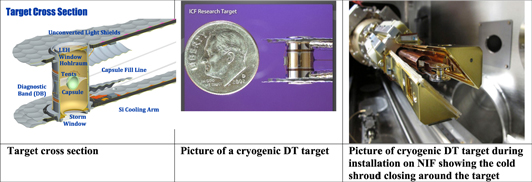
Figure 3. ICF target configuration at the NIF.
Download figure:
Standard image High-resolution imagePrecision engineering design and applied materials research has enabled the target manufacturing team to meet the stringent ICF requirements for capsule surface finish and positioning, performance at cryogenic temperatures, and robustness during assembly and fielding. Assembly stations, tooling and procedures are available to meet target-positioning requirements, and component design changes are implemented to improve assembly yield and throughput [36]. The target technology research and development is continuous by necessity to maintain the ability to respond dynamically as new targets or new diagnostics are required. The ignition target consists of an ablator capsule and fill tube, hohlraum, laser entrance hole (LEH) inserts, thin polymer membranes ('tents'), and the thermal mechanical package (TMP). A silicon cooling arm, thermal shell, diagnostic band, windows, heaters and sensors, tamping gas line, and wiring harness comprise the TMP. Production of the capsule starts with a very smooth, very spherical plastic mandrel, the form on which the silicon-doped plastic (CH) is deposited as the mandrel is rolled or rotated. Following deposition, the capsules are polished. Because the mandrel is plastic, it can be removed by carefully heating the shell to pyrolyze the plastic, resulting in gases that can escape via permeation through the capsule. HDC [37–39] and beryllium capsules [40–42] are also used and manufactured by similar methods. A five-to-ten micron fill hole is then laser-drilled. A precisely drawn and finished tube of glass is used to make the five-to-ten-micron fill tube that is attached to the capsule for DT gas delivery.
The ignition hohlraum is a gold or gold-coated (originally proposed to prevent oxidation) uranium cylinder designed to couple as much laser energy to the capsule as possible. The layers are sputter-deposited on a precision-machined mandrel, which is etched away after deposition and machining are complete. A flange at the waist of the hohlraum supplies an attachment surface for the thin Formvar 'tent' that positions the capsule.
The LEH inserts are machined as separate parts to allow for various LEH diameters, and the LEH windows are aluminum-coated 500 nm thick polyimide film. The diagnostic band joins and aligns the sub-assembled target halves and provides ports for characterization access. The TMP precisely positions the hohlraum, manages the thermal environment of the hohlraum and capsule, and provides a modular platform for various diagnostic configurations without changes to the remaining components. The TMP consists of two precision-fabricated aluminum shells joined by a precision-fabricated band with cutouts to accommodate various diagnostics requirements. Two silicon cooling arms attached to either end of the TMP assembly conduct heat away from the hohlraum to maintain the required temperature. These are lithographically etched to create a precise heat transfer path that ensures temperature uniformity in the target. Heaters located on the TMP shells are then used to produce a nearly spherical isotherm around the capsule. Tamping gas lines deliver helium gas (or other gasses) to the hohlraum to mitigate the interaction between ablated material from the hohlraum walls, as this interaction can steer and scatter the laser light entering the hohlraum.
Components (hohlraum, capsule, etc) for the various platforms are produced largely by General Atomics Corporation. The time to the target use is critical regarding the quantified gas composition (e.g. due to tritium decay). The formation of frozen DT layers is described in [43–45].
We note that it also possible to attach small amounts of target material (thin foils) to the hohlraum or as a thin layer doped into the capsule shell to study for example neutron induced nuclear reactions utilizing radiochemistry methods (see 2.1.9).
2. Experimental platform characterization
2.1. Nuclear diagnostic
The development of long pulse high energy (MJ, ns) laser systems like the NIF and proposed short pulsed laser (kJ, fs) facilities like ELI open entirely new domains for experimental research in HED science. In these domains, relatively large amounts of matter can be heated to high temperature and compressed to high densities. The atomic constituents of that hot, compressed matter can undergo nuclear processes, and the product of these processes, neturons, gamma rays, and high energy particles, are likely the only unambiguous signals with which to diagnose the environment itself as well as the effect of that environment on the nuclear processes. The applications for applied and basic research at these facilities lie in extreme matter research, astro-physics in general and nuclear astro-physics in particular. Research scenarios where a long-pulsed laser drive provides adiabatically compressed high density matter and where a short-pulse laser drive provides MeV/u particle beams for diagnostic and nuclear reaction studies in HED environments are possible. The development of adequate diagnostic instrumentation for accurate and precise measurements in the short time and high density domains is being intensively pursued at the NIF. It should be noted that these developments are not restricted to high energy laser systems; upcoming new sophisticated relativistic particle beam facilities will benefit from these developments as well. Several of these developments are described below along with their performance and potential applications [46].
A total of 65 diagnostics units are established at the NIF (figure 4), and are essential to monitor laser performance and implosion characteristics. The non-nuclear (for a review see [47, 48]) and nuclear diagnostics [47, 49] have been developed predominantly as part of the ICF program, but these diagnostics have expanded into a general HED program, where the nuclear diagnostic experimental suite provides the essential tools for projects focused on nuclear science. It should be emphasized that the nuclear diagnostics using spectral analysis, activation products, and gamma-ray detection take advantage of the inherent nuclear reaction product insensitivity to distorting fields and low energy charged particle background.
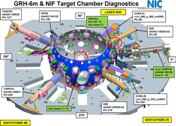
Figure 4. Over 65 diagnostic instruments are located at the NIF. Eleven of them are dedicated nuclear diagnostic instruments, which view the target center from different directions.
Download figure:
Standard image High-resolution imageA comprehensive characterization of the gas, fuel and typical hydrocarbon ablator assembly is essential in the analysis of ICF implosion experiments as well as for the performance and analysis of HED experiments [47]. Attaining laboratory-scale ignition relies crucially upon symmetric convergence of a sufficiently dense fuel assembly. Although there are many implosion diagnostics currently fielded at the NIF [49], these diagnostics generally rely upon x-ray emission to probe the hot core conditions thus providing only indirect information, usually derived from opacity variations, about the much colder fuel and remaining ablator assembly. Diagnostic approaches that rely upon nuclear processes are more amenable to this analysis, especially neutron scattering phenomena, since non-burning or non-emitting material can be probed. For example, the inelastic collisions of the fusion-produced neutrons with the compressed fuel and ablator induces an energy loss in the escaping neutrons that is cleanly monitored in the 10–12 MeV spectral range by the nTOF detectors [48]. This process is dominated by the scattering from the dense DT layer and is thus much less sensitive to the remaining hydrocarbon ablator. A 3D image of these scattered neutrons in the 6–12 MeV range is routinely available for implosions producing greater than 5 × 10¹³ neutron yield.
The development of the GRH diagnostic [49] complements these approaches and provides a direct experimental determination of the areal density associated with the hydrocarbon or high-density carbon ablator. Although the primary function of the GRH measurements is to provide a time history of the core fusion process by monitoring DT-emission, it is possible to extract the bright 12C(n; n'γ) γ emission at 4.4 MeV from the total gamma-ray emission. This gamma-ray signal is unaffected by any of the competing D or T scattering processes that complicate the interpretation of the nTOF-derived neutron spectra and neutron images so that the calibrated time-integrated emission directly measures the spatially integrated carbon areal density from the ablator. Also, the nTOF spectra depend upon spatial variations in the shell density distribution along the LOS between the burning core and the detector. Since the gamma-ray emission is almost spatially isotropic, a single measurement inherently produces a shell-averaged areal density.
The significance of these data in characterizing implosion performance arises primarily from its implications for mixing of ablator mass into the dense DT fuel layer region. More specifically, if the remaining ablator mass is approximately constant in a series of nearly identical implosion experiments then an increase in the measured ablator areal density implies entrainment of ablator material into the denser DT fuel layer. Since hydrodynamic instabilities are a dominant failure mechanism [48], trends in the ablator areal density might supply important information about the growth of these instabilities particularly at the DT fuel-ablator interface.
An analysis of the recent series of high-yield implosion experiments conducted at the NIF provides an example of the utility of this approach [50]. With neutron yields greater than 1 × 10¹⁵ signal detection in the GRH becomes statistically robust. In the following section, the GRH experimental apparatus is described and in the third section, details of a simple model are provided, supplying a coherent framework in which to view the data.
2.1.1. Neutron activation diagnostics (NAD)
The NAD is based on measuring neutron-induced activation in different materials [51–53]. The neutrons are produced in fusion reactions of DD, DT and THD surrogate shots (see p 3, table 1). For example, the 115In(n, n)115 min reaction measures the D(D, n) neutron yield; both 90Zr(n, 2n)89Zr and 63Cu(n, 2n)62Cu measure the D(T, n) primary (13–15 MeV) (figure 5) yield. Tertiary (>15 MeV) neutron yields from energetically up-scattered and reaction-in-flight neutrons are measured utilizing the 209Bi(n, 4n) and169Tm(n, 3n) reactions [54]. Indium and zirconium activation are used together to determine the DSR along many lines of sight [55]. These calibrated diagnostics provide the absolute yield measurements for the principal D (T, n) α reaction at the NIF independent of any other diagnostic system; in particular, yield measurements from NTOF diagnostics are calibrated to the activation yield.
The primary neutron yield, YDT, is calculated from the activity measurement of the sample by YDT = A0/(prx · εirr), where A0 is the initial activity product nuclei at t = 0; prx is the reaction probability for activation foil per neutron; and εirr is the irradiation efficiency (neutron fraction at emission center at subtended solid angle at activation target). The reaction probability per primary neutron, prs is calculated as prs = Ntarget/4πR2ʃdn/dE σ(E)dE, where Ntarget is the number of target nuclei; R is the radius of the target from target center; and n is the number of neutrons emitted at target center.
The specific thin disks of activation material, Zr for activation with 14 MeV neutrons from DT in 90Zr(n, 2n)89Zr reactions, are located in insertion devices at specific locations both within the chamber and are also distributed at specific locations on the outside of NIF chamber flanges (FNAD) (figure 6) [56, 57]. The distribution of measured neutron yields monitors the absolute fuel ρR and its angular distribution in high yield shots since a larger ρR means less activation in the direction of the corresponding activation target due to greater scattering of the fusion neutrons out of that line-of-sight. An accuracy of better than 5% (absolute) and 1%–2% (relative) for shot-to-shot measurements is required and achieved. Substantial experimental effort is dedicated to determining the symmetry and shape of the burning core in ignition experiments. Anisotropy of the cold fuel in the stagnated assembly is believed to be a primary cause of performance degradations since shell asymmetries suggest inefficient compression. This energy deficit appears in radiation-hydrodynamic simulation studies which highlighted the role of insufficient kinetic energy coupling to the hot core. This limited coupling has observable anisotropic nuclear diagnostic signatures, hence spatially resolved areal density diagnostics are essential to diagnosing and optimizing implosion performance.
The neutron spectrum, dn/dE (θ, ϕ), seen at a particular FNAD location, is the burning core neutron production integrated along the attenuation path r through a medium with variable density. The material properties of the medium are also a function of radial path, consisting of burning DT gas, cold compressed DT fuel, and ablator material. Although the ablator mass distribution during the shell implosion phase is measured in surrogate experiments, core emission from a high compression implosion limits the minimum radius at which backlit shell radiography is useful in determining the shape and density of the cold fuel. Path integrals from the hot spot to TC wall can be substantially different between FNAD lines of sight, depending strongly on the shape of the cold fuel. Thus the FNAD signatures offer valuable insight into the important stagnation regime. As an adjunct to the FNAD assembled fuel signatures, a line-of-sight (equatorial) view of both the hot core shape and the cold DT fuel are directly measured by neutron imaging (NI). While artifacts of cold fuel geometry may be seen in the down-scattered neutron image, metrology of two three-dimensional objects (burning fuel and shell) by means of a single line-of-sight 2D image projection, results in an unconstrained family of solutions. In particular, the kinematically unfavorable large angle neutron scattering makes any cold fuel regions at large angles and distances from the NI LOS virtually invisible. Thus the FNAD diagnostic complements and augments the neutron image analysis of the stagnated assembly.

Figure 5. Typical NIF DT Neutron spectrum with primary measurement reaction cross sections.
Download figure:
Standard image High-resolution image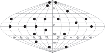
Figure 6. NIF Flange-NAD deployment. Zirconium activation samples are placed on exterior blind flanges around the NIF target chamber, removed post-shot, and analyzed for 89Zr induced activity.
Download figure:
Standard image High-resolution imageAny one of the specific FNAD locations samples all source neutrons emitted in its direction by the burning core. Those neutrons are attenuated by interstitial cold fuel density integrated along the neutron path length. The solid angular area sampled is then the ratio of the area of emitted neutron beam to the spherical area encompassed at the radius of scattering. In terms of the geometry illustrated in figure 7, assuming circular profiles in the perpendicular dimension, the emitted beam area (π/4)  divided by the spherical scattering area
  gives a sampled solid angle of l2/16r2 when li ≥ 2ri and thus the object casts an umbral neutron shadow on the TC wall. The umbral shadow results in a sharp angular gradient in the un-scattered neutron flux and thus proximate FNAD locations show large variations.
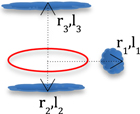
Figure 7. Path integrals from the hot spot to target chamber wall may be substantially different between FNAD lines of sight, depending strongly on the shape of the cold fuel and its distance from the hot spot.
Download figure:
Standard image High-resolution imageWhen li < 2ri the scattering mass no longer obscures the entire hot spot and as such casts only an antumbral shadow on the TC wall. In this case, FNADs over a wide area would see a similar small depression in source strength caused by the small obscuring object.
A bulk center-of-mass velocity of the burning core may also Doppler shift the neutron spectrum. This effect changes the spectrum-averaged activation cross section, as the velocity vector projection changes with observation position.
Studies on warm, gas-filled exploding pusher target implosions reported significant anisotropy attributed to target alignment [57], target mounting [58], capsule defects [59], and non-uniform illumination [60]. For example, the effect of dropping two of the 48 NIF laser quads leads to substantial asymmetry in density and implosion velocity without precise redistribution of the remaining laser energy.
The FNAD activation data and analysis can quantify the effects of bulk velocity within the hot core, especially with respect to the subsequent neutron yield anisotropy. An example of this analysis is presented in figure 8. The relative activation ratios at the different sites previously displayed in figure 6 are plotted with a superimposed low-order spherical harmonic fit to highlight the anisotropic activation distribution for shot N120217-001. Since this shot had inconsequential areal density by design, the observed asymmetries may be ascribed to bulk velocity gradients in the burning plasma. Both a low-order north–south feature and a large amount of high-mode structure are apparent.
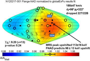
Figure 8. Direct drive exploding pusher shot N120217-001 FNAD measurement. The Doppler shift of the neutron spectrum is measured as a consistent 3-component velocity on the same number of DT source neutrons at all locations around the target chamber; the shift was induced by dropping two of the 48 laser quads hence creating a pronounced x-ray drive imbalance.
Download figure:
Standard image High-resolution imageAn analysis that assigns a coherent bulk neutron velocity of 100 km s−1 results in 3.16% additional induced activity in the direction of the velocity, 2.77% of which is due to the change in cross section over the energy shift. The remaining 0.39% is due to the increased number of neutrons emitted in the velocity direction in the lab frame. By detecting the coherent shift in activation around the TC, a single three-component velocity vector may be fit.
Removing the velocity effect on the reported activation ratios (both fluid flow and Doppler shift) leaves just the effect of scattering mass in each FNAD LOS.
An FNADs system based on a lanthanum bromide scintillators and compact gamma spectrometers installed in the target bay is being developed to provide immediate postshot readout of yield [58]. This system will have additional capability to measure multiple DT neutron reactions and other neutron source terms, such as TT and DD fusion reaction neutrons [59, 60].
2.1.2. Neutron time-of-flight diagnostic (nToF)
In ICF experiments with D2, DT or THD targets the nToF diagnostics measure the neutron yield as a function of neutron energy by recording detector signal strength over time using the known flight path length to deduce the neutron energy. There are several nToF detectors at different lines-of-sight on the NIF whose purpose is to measure different aspects of the neutron spectrum with high accuracy. All nToF detectors have their signals recorded with high bandwidth multi-channel digital oscilloscopes. It is important to note that in contrast to most beam target experiments these nToF detectors operate in current mode looking at the combined signal of many neutrons in a single flash. Most nToF detectors utilize scintillation detectors coupled to PMT and/or PD, however a few detectors use CVD diamonds. Those CVDs were chosen for use in measurements where sensitivity was of lower importance and a fast time response was needed. However, it has been discovered that the IRF of most CVDs in use is not stable; current efforts are therefore exclusively dedicated to the scintillation detectors. Two legacy nToF detectors are at 4.5 m from TCC, which are using fast scintillation detectors. Due to the short flight path those detectors can only be used for measuring the overall neutron yield; one of them is dedicated for low yield shots (107–1013 neutrons) while the other covers the yield region from 1013 to 1015 neutrons.
For measurements of spectral information such as ion temperature and the ratio of down scattered neutrons relative to the primary neutron yield down-scattered ratio (DSR), four especially developed detectors are being employed at a distance of about 20 m (the exact distance varies by detector) from TCC. Those detectors use an LLNL developed scintillator [61], which has an extremely low afterglow and is incorporated in a low mass housing to reduce background from neutron scattering. Figure 9 shows a schematic of the detector housing with its mounting and the scintillator inside. Due to the above-mentioned improvements, this detector allows the measurement of the down-scattered neutron spectrum with high accuracy.
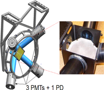
Figure 9. The nToF detector for spectral measurements; the insert shows the scintillation crystal.
Download figure:
Standard image High-resolution imageTo achieve the highest possible signal to noise ratio, each PMT/PD signal is split up and recorded on 4 scope channels with a different sensitivity. Two of these channels are stitched together to improve the dynamic range of the data acquisition needed for DSR measurement.
The detectors were designed to obtain spectral information on shots with neutron yields as low as 1010. This range is obtained by using PMTs with different gains with different light attenuators in front of them. The IRF of these detectors is 4.4 ns FWHM giving them a neutron energy resolution of about 300 keV for 14 MeV neutrons.
The neutron spectrum is characterized by a certain number of key quantities (figure 10(a)): for a DT shot those are the primary neutron yield, defined as the number of neutrons in the 13–15 MeV energy region and the second central moment of the primary neutron peak and the DSR defined as the ratio of neutron yields from 10 to 12 MeV relative to those from 13 to 15 MeV. If there are no motion effects (e.g. averaged velocity distributions in hot spot [62]) broadening the neutron peak then the second central moment is directly proportional to the neutron yield weighted average ion temperature of the plasma [63, 64]. The DSR provides valuable information about the fuel ρR achieved in the implosion. In addition, gated PMTs measure the peak of the DD neutrons emitted from the DT capsule (see figure 7(b)): using a model for the background under this peak the DD neutron yield and ion temperature can be determined.

Figure 10. Forward fits to the nToF spectra: (a) on the left the DT peak with the down-scatter region (b) the DD peak sitting on top of down-scattered neutron background. Note that the down-scatter part on the DD peak had to be fixed by a model relating it to the DSR on the DT peak since the shape of the background could easily incorporate it.
Download figure:
Standard image High-resolution imageNeutron yield measurements with nToF detectors are only relative; to obtain an absolute yield a calibration to an appropriate NAD is needed. The accuracy of all these measurements is as follows: 7% for the neutron yield coming from the NAD calibration, 300 eV for ion temperature and 10% for the DSR measurement. The nToF spectra are analyzed by using a forward fit of the data, which involves parameterizing the neutron spectrum with a model, taking into account the detector sensitivity and the beam line attenuation and convolving it with the IRF; an example fit to the data is shown in figure 10.
The fit function has the form

where I(E) denotes the model of the neutron spectrum, s(E) is the sensitivity of the detector to the given neutron energy, a(E) is the beam line attenuation factor, E(t) is the neutron energy as a function of time-of-flight, dE/dt converts the energy spectrum into time-of-flight space, R(t) is the instrument response. The neutron energy as a function of time-of-flight can be calculated as E(t) = mnc2(γ − 1) using γ = (1 − β2)−1/2 and β = t/tγ,with tγ being the time-of-flight of a photon and mn the mass of the neutron. This relationship determines the neutron energy change dE/dt = mnc2γ3β3/tγ. The determination of the instrument response R(t), the scintillator sensitivity s(E), the beam line attenuation a(E), as well as the models used for I(E) and their application in the data analysis are explained in [65].
The burn-weighted ion temperature of the fuel in ICF targets can be deduced from the neutron energy spectrum for DD yields >1010 and for DT yields of >1011 (if bulk fluid motions are negligible). It is should be noted that an extension of the flight pass (e.g. to 100 m) makes a correction of the energy spectrum (peak width) at the primary peak for the instrumental time resolution (IRF) negligible.
To convert nToF into neutron energy the time offsets for the signal must be known accurately. The time of the scope trace can be interpreted as a sum of several contributions: t = tE + tBang + tLPOM + tfidu + t0 where tE is the time-of-flight of the neutron from TCC to the detector due to its initial energy, tBang is the bang time, i.e. the time it takes from the beginning of the laser pulse to the nuclear burn of the fuel, tLPOM is the time between the 0 time of Laser Program Operations Management (LPOM) and the actual time when the laser beams hit the target, tfidu is the position of the timing fiducial on the scope trace and t0 is a time offset that has to be determined from a x-ray timing shot. Comparing the t0 for different timing shots the uncertainty of t0 has been established as σ ≈ 30 ps. An x-ray timing shot produces x-ray emission by illuminating a gold disk with an 88 ps laser pulse. Besides establishing detector timing these shots are also used for constructing the IRF of the nToF detectors. Since the width of 88 ps is negligibly small compared to the response of the instrument the signal recorded on a timing shot serves as the IRF for x-rays. To convert it to an IRF for neutrons the neutron transit time through the 2.5 cm thick scintillation crystal must be taken into account. This is done by using an MCNP simulation to determine the energy deposition of the neutrons over time and convolving it with the x-ray IRF. This procedure must be separately repeated for DD (2.45 MeV) neutrons and DT (14.05 MeV) neutrons since their transit time is significantly different.
In addition to neutron yield and ion temperature, the model described by Ballabio et al [64] relates the mean energy of the neutron peak to the ion temperature; this relationship thus identifies the offset of the peak position as a fluid velocity. This relationship holds independently for both the DD and the DT neutron emission peaks. The uncertainty in this velocity measurement is approximately 15 km s−1, but it is typically observed that the velocity obtained from the DD peak is systematically 10–25 km s−1 lower than the one from the DT peak. One interpretation of this observation is that the ion temperature deduced from the width of the peaks is too high since collective motion can also broaden the peak. Another difference is that the DD peak is much more strongly affected by down-scatter: on a shot with a DSR of 5% more than 50% of the DD neutrons scatter out of the peak region, the exact impact on how this affects the results of the data analysis is not yet understood [66].
The nToF diagnostic is complementary to other nuclear diagnostics (e.g. radiochemistry, NI, neutron activation and γ-ray reaction history) and some of the non-nuclear diagnostics thus providing some redundancy. No single diagnostic alone will provide unambiguous information which allows to infer progress on the ignition experiments. A correlated data analysis is needed to evaluate the ignition or failure conditions.
2.1.3. Magnetic recoil spectrometer (MRS)
Based on the magnet-based neutron spectrometer developed for Magnetic Confinement Fusion [67] and installed on the Joint European Torus in Oxford, UK [68], the MRS concept for ICF applications [69, 70] was first demonstrated in 2008 at the OMEGA laser facility. Another MRS system, described in detail in [71–74], was subsequently developed for the NIF (figure 11). This system provides time-integrated information about the neutron spectrum (in the range of 4–23 MeV) through measurements of recoil deuterons produced by neutrons incident on a deuterated polyethylene (CD) foil located 26 cm from the implosion. A small fraction of the recoil deuterons produced in the forward direction is selected by a 20 cm2 aperture positioned 570 cm from the foil. These recoil deuterons are momentum analyzed and focused by a magnet onto an array of CR-39 detectors positioned at the focal plane of the spectrometer. Both the magnet and detector are located on the outside of the NIF TC wall. From the measured recoil-deuteron spectrum, the neutron spectrum can be reconstructed. The detector array consists of nine single-use CR-39 detectors, which are processed post-shot in a dedicated etch- and scan laboratory. These types of detectors have the advantages of being 100% efficient for detecting the recoil deuterons and very insensitive to background neutrons, gamma rays and EMP, which allows for measurements with excellent signal-to-background (S/B).
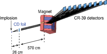
Figure 11. A schematic picture of MRS on the NIF. The CD foil is 26 cm from the implosion; the magnet is positioned outside the target chamber, 570 cm from the foil. For detection of the forward scattered recoil deuterons nine 6 × 5 cm2 CR-39 detectors are positioned at the focal plane of the system. The trajectories shown are for deuteron energies from ∼3.5 to 20 MeV. The length of the detector plane is 84 cm. Reprinted with permission from [75]. Copyright (2014), AIP Publishing LLC.
Download figure:
Standard image High-resolution imageMRS routinely measures the neutron spectrum from cryogenically layered DT target implosions [73], from which DT yield, areal density (ρR) and ion temperature are determined (ρR is inferred from the ratio of down-scattered neutrons (10–12 MeV) to primary neutrons (13–15 MeV)). MRS also measures directional flow velocities [74], neutron yields from the T + T reaction [76] and CH ablator areal density in symmetry-capsule implosions with low DT fuel-ρR [75]. MRS is ab initio calibrated and is one of only two independent ways of measuring absolute DT yields on the NIF; the other one is the NAD technique (described later in this section).
An optimal balance between detection efficiency and resolution for a set application can be obtained by varying the thickness and size of the CD foil. For lower yields, thicker foils are used to optimize signal statistics at the expense of resolution. At higher yields, thinner foils are used for better resolution and to avoid track overlap on the CR-39 at high signal levels [77]. As the main sources of background are due to unscattered neutrons and neutrons scattered off structures near the MRS CR-39 detector system, the signal to background is reduced when thinner foils are used.
To allow for high-fidelity analysis at low signal levels with high relative background, such as for the DSR measurements, a dedicated CR-39 processing technique, the so-called coincidence counting technique [78], has been developed. This involves processing the CR-39 detectors in two steps, eliminating background by only accepting as signal events that occur in the same location in the two layers, and allows up to ∼2 orders of magnitude improvement in S/B.
The systematic uncertainty in the measured absolute yield comes from the uncertainty in the MRS geometry and inaccuracy of the CD foil characterization. For some configurations, the systematic uncertainty is as low as 4%. The systematic uncertainty in the measured DSR is set only by the relative uncertainty in the n, D elastic cross section at 10–12 MeV and 13–15 MeV and is less than 5%.
MRS can also be operated in charged-particle mode to measure the energy spectra of protons (Ep ∼ 6–40 MeV) or deuterons (Ed ∼ 2.5–20 MeV) directly from the implosion with an energy resolution of ∼0.15 MeV. In this case, MRS is fielded without the CD foil, and has a detection efficiency of 4.3 × 10⁻⁶ set by the solid angle covered by the magnet aperture. The dynamic range for MRS in this mode depends on the shape of the probed spectrum; peaked spectra can be measured from ∼108 upwards with enough signal to pick out the tracks from the intrinsic CR-39 background noise and broad spectra covering several MeV could be measured up to at least 1011 without running into track overlap on the CR-39.
2.1.4. NIS Neutron Imaging Diagnostic
The NIF NIS was installed in 2010, commissioned in 2011 and is presently being used to provide data on the size and shape of the fusion hotspot and the surrounding cold fuel for ICF implosions [79]. This system is comprised of three basic pieces: an aperture array is used to form the neutron images, a detector system is used to measure the neutron flux passing through the pinhole array, and reconstruction algorithms have been developed to extract the neutron source distributions from the recorded images. The application of this technique to measure the underlying burning fuel distribution has been developed in the past decade and now implemented at NIF [80–84].
This detector system [85] can collect two images, which are fast gated and independently timed. Because the detector array is positioned 28 m from the neutron source, the neutron arrival time at the detector is correlated to the neutron energies, allowing measurement of the neutron source distributions from two energy ranges by gating the detectors at two different times. Typically, one detector is gated to view the 14 MeV neutrons (13–17 MeV), which are generated from DT fusion processes, while the second detector is gated to measure the source distribution of lower energy neutrons, typically in the range from 6 to 12 MeV. These lower energy neutrons are predominantly DT fusion neutrons that have scattered in the surrounding cold fuel and, therefore, provide information on the distribution of cold fuel surrounding the hotspot. By measuring these sources along the same LOS the images can be co-registered allowing the two images to be placed relative to each other.
Because of the long mean free path of neutrons within the aperture material, the NI system forms images using extended apertures or 'pinholes' in materials with short interaction lengths. The aperture array currently in use at NIF is composed of triangular pinholes and mini-penumbral apertures machined along the 20 cm length of wedged gold layers. Gold has an interaction length of ∼3 cm for 14 MeV neutrons. The pinholes have an equilateral, triangular cross-section and taper from a height of 0–210 μm in the direction of neutron propagation. Each tapered pinhole provides a field of view of approximately 200 μm at 26.5 cm from the entrance face of the aperture array. A total of 20 pinholes have been precision machined into four tapered gold layers, which are stacked to form the aperture array. The mini-penumbral apertures are double-tapered cylinders with a 273 μm input aperture diameter, a 300 μm waist diameter, and a 437 μm exit aperture diameter. Three apertures were formed by machining three half cylinders into each of two gold slabs and precision stacking the two layers to form the penumbral apertures. Each aperture has a field of view of 200 μm. At the present operating position, the field of view of the ensemble of pinholes to <0.7 mm horizontally and <0.5 mm vertically, as each pinhole now points at a slightly different location at the source.
The image recording system is located 28 m from TCC with two collimators placed along the neutron flight path providing a measurement environment with low neutron backgrounds.
Neutrons that form the images interact with a coherent scintillating fiber array. This fiber array is 160 mm square and is composed of BCF-99-55 scintillating fibers. The round fibers are 250 μm in diameter and 5 cm long. This light is transported within the fibers to the two ends of the fiber array. A turning mirror located at the upstream end of the fiber array directs the scintillation light into an optical lens, which forms an image on a 75 mm micro-channel plate (MCP). This MCP provides signal gain and the fast gating of the image collection system. The output image of the 75 mm channel plate is reduced to 37 mm with a fiber taper that couples to the fiber optic window of a SI-1000 CCD camera.
The light that exits the fiber on the downstream ends is collected into a fiber taper reducing the image from 160 to 75 mm into a second 75 mm MCP. The output of this MCP is collected with a 37 mm coherent fiber 'rope' and directed to a second SI-1000 CCD camera. The detector resolution at the scintillator plane of both image recording systems has been measured to be ∼1.2 mm FWHM, resulting in 15 μm resolution at the source plane after correcting for the magnification.
By injecting a pattern of neutrons into the scintillator and gating both imaging systems at the same time, the two NI systems have been spatially calibrated into the same coordinate system. This allows the primary neutron image to be overlaid on the down scattered neutron image to within ∼5 μm, allowing detailed analysis of the image data correlating neutron emission with the fuel assembly.
Because of the small neutron source sizes and the triangular shape of the neutron pinholes, significant effort has been devoted to the development of analysis procedures to remove imaging distortions. Figure 12 shows a primary and down scattered neutron image from all the pinholes for shot N140304, the highest yielding NIF ICF implosion to date, which generated nearly 1016 neutrons and figure 13 shows the five pinholes with the field of view overlapping the neutron source.
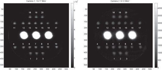
Figure 12. Left: 13–16 MeV neutron image from NIF shot N140304, the ICF implosion yielding nearly 1016 neutrons. Right: 6–12 MeV neutron image from the same shot.
Download figure:
Standard image High-resolution image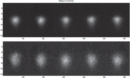
Figure 13. Composite image of the five best pointed pinholes for this shot. Top: primary neutron image and bottom: scattered neutron image. The residual shape of the neutron image forming pinhole. The distortion of this image is removed in analysis.
Download figure:
Standard image High-resolution imageSeveral maximum-likelihood estimate techniques have been employed to remove the distortions shown in figure 13. The distortions introduced by neutrons interacting with the aperture housing is calculated and characterized through a four-dimensional matrix. This four-dimensional matrix maps the attenuation properties from each position at the source plane to each position at the detector plane. The two-dimensional source plane position is then mapped into the two-dimensions of the image plane, and these transport properties are characterized within this four-dimensional matrix.
With this formulation, the reconstruction process can be characterized as the inversion of this matrix formula. This is a notoriously difficult problem as this ill-posed inversion is under-constrained. Maximum-likelihood techniques have been formulated for this inversion process [86]. An algorithm which assumes Gaussian noise and employs an adaptive step size has been shown to be the most robust for reconstructions of the underlying sources. Because multiple pinholes each provide an image from a NIF implosion, four-dimensional matrices are calculated for the detailed pointing solution for each pinhole. The maximum-likelihood techniques are used to reconstruct the underlying source that is consistent with each pinhole image. This technique provides significant enhancement over single pinhole techniques as any systematic errors introduced by each pinhole are partially corrected when simultaneously used in an ensemble reconstruction.
Figures 14 and 15 show the reconstructed results of the data shown in figure 13, showing the underlying reconstructed source as well as the 17% contour, which has been fit to Legendre polynomials. The 17% contour is typically reported for NIF experiments, as this contour level should closely agree with the 17% high-energy x-ray contour.
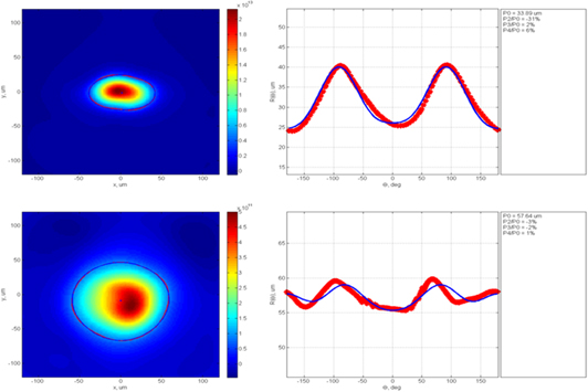
Figure 14. Reconstructed hot-spot (13–17 MeV neutrons) and cold fuel (6–12 MeV neutrons). The 17% contour was identified and fit to Legendre polynomials to characterize the outer extent of the hot-spot and cold fuel.
Download figure:
Standard image High-resolution image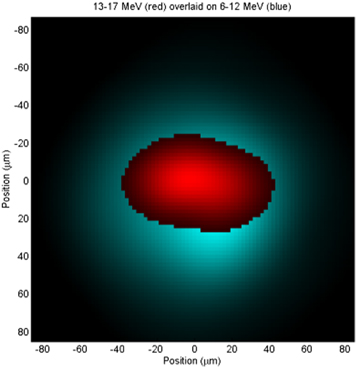
Figure 15. The hot spot image is overlaid on the cold fuel image with relative position alignment of 5 μm.
Download figure:
Standard image High-resolution imageThe NI system at NIF has been installed and commissioned and is providing hotspot and cold-fuel shape information to the National Ignition Campaign for tuning the implosion of the ignition capsules. The large amount of data that has been collected since early 2011 has provided substantial gains in system characterization, data analysis and source reconstruction algorithms. This data continues to be analyzed to further improve system performance and the development of analysis algorithms.
This technique has proven so powerful [87, 88] that an effort is underway to install a second and third NI LOS along the polar and another equatorial LOS at NIF. The combination of this data would provide information on the three-dimensional nature of the implosion system at stagnation.
2.1.5. Integrated neutron imaging
In the idealized picture of a compressed DT capsule at stagnation, a spherical shell of remaining ablator surrounds a spherical shell of the remaining cold fuel that in turn surrounds a sphere of burning DT fuel. Reality, however, imposes itself during compression in the form of asymmetric drive, native roughness of the capsule, the fill tube, the tents that hold the capsule, and instabilities. These features and effects can cause distortions and mixing and produce asymmetries in the compressed ablator and DT fuel and in the burning hot spot. Since these realities can also limit the yield, understanding the spatial features of the hotspot, cold fuel and ablator throughout the compression and burn is crucial.
While radiography and imaging of self-emission x-rays are the primary methods for observing the symmetry of the capsule during compression [89–91], current radiography methods go blind due to the high capsule density prior to stagnation, and the x-ray images are strongly influenced by the emitting materials and opacity near stagnation. To understand the shape of the burn volume, whether the fuel is burning where it is emitting x-rays, or how the remaining ablator or cold fuel are distributed around the burning core, the 14.1 MeV neutrons that are produced by the burning fuel provide a useful probe.
Direct NI provides an immediate picture of the burning DT source since only a small fraction of the neutrons interacts before escaping the compressed capsule. The fraction of neutrons that does interact with the compressed capsule before exiting is also useful. Neutrons that down scatter from the cold DT fuel and lose energy can be separated from the 14.1 MeV neutrons by time of flight and imaged to obtain information on the density of the remaining cold fuel. Other neutrons can interact with the carbon in plastic ablators and scatter, producing a 4.43 MeV γ-ray through the reaction:

Imaging those γ-rays then provides information on the density of the remaining ablator.
The existing NIS on the 90–315 LOS [92], which is described above, provides direct images of the fusion hot spot by imaging the 14.1 MeV neutrons and images of the cold fuel by imaging of the down-scattered neutrons. By sacrificing one of these images and gating one arm of the NIS system on the photon arrival, this system has also demonstrated imaging of γ-rays from the remaining ablator. Due to the inherently three-dimensional nature of the implosion, single views of the 14.1 MeV neutrons, the down-scattered neutrons, or the γ-rays are insufficient to understand the source volumes. For imaging the burn volume, simulations have shown that two views (figure 16)—one equatorial and one polar—reduce the assumptions required for 3D reconstruction and that three near-orthogonal views eliminate the need for symmetry assumptions and eliminate most reconstruction artifacts. Reconstructions from γ-ray images should perform similarly. For the down-scattered images, where the kinematics of the scattering cause images to sample strongly in the direction of the LOS, one would expect six views to be required along three near-orthogonal axes.
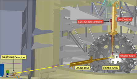
Figure 16. The polar and equatorial lines of site for the n-imagers at the NIF chamber.
Download figure:
Standard image High-resolution imageMoving beyond a single view with two images will require additional lines of sight, each of which has integrated measurements of the 14.1 MeV neutron, down-scattered neutron and γ-ray images, preferably with x-ray imaging on the same or nearby lines of sight.
As part of the move to multiple lines of sight, the NIF has installed an energy-integrated neutron imager on the 5.25–225 LOS. This imager uses a detector stack of four pair of 2 mm polyethylene sheets followed by image plates. The detector relies on (n, p) reactions in the high-density polyethylene to produce protons that interact with the image plate to record an image [93]. While it has lower efficiency than the 50 mm thick BCF-99-55 scintillating fiber array used on 90–315, this imaging stack has excellent resolution (∼650 μm FWHM point spread function versus 1.1 mm for the BCF-99-55 fiber array) and allows imaging on an 8.2 m LOS. Adding energy resolution or γ-ray imaging on this LOS will require improved scintillators. An additional equatorial LOS is also planned to allow the required set of near orthogonal measurements.
2.1.6. Temporal gamma-ray reaction history (GRH) diagnostic
In ICF experiments nuclear reaction products are produced over the burn time in the region of the burning fuel. The MeV neutrons and gamma rays produced probe the burning fuel uniquely since they escape from the capsule-centered burn region relatively undistorted. The nuclear bang time—the time interval from onset of the laser pulse to the maximum of neutron and fusion gamma emission—is measured accurately via the time resolved detection of neutrons and gamma rays. The x-ray signals provide a bang time as well but are subject to opacity issues and competing signals from other pre-burn sources such as supra-thermal electron Bremsstrahlung produced by the hohlraum plasma. The time history of the nuclear DT fusion reaction (burn), the evolution of the ignition to peak burn and beyond, is most promptly determined by monitoring the DT fusion gammas that have primary peak energy at 16.7 MeV with high time resolution. The gammas have no time-of-flight dispersion along their flight path; the dynamic range, however, is yield limited because of the 4 × 10⁻⁵ branching ratio of DT fusion gammas to the 14.1 MeV neutron emission [94].
The GRH diagnostic employs Cherenkov counters running in current mode in four separate gas cells with variable pressures to adjust the Cherenkov threshold on Compton-scattered electrons in the active detector volume [95]. The chosen thresholds typically correspond to γ-ray energies of 10, 8, 4.5 and 2.9 MeV. The 10 and 8 MeV thresholds measure the fusion γ-rays at 16.7 MeV. Gamma rays produced from neutron interactions with materials surrounding the target dominate the 4.5 MeV threshold detector, while the 2.9 MeV signal divides about evenly between 12C (n; n'γ4.4) and the neutron-induced γ-ray background.
In the GRH itself, gammas are converted into relativistic electrons, primarily by Compton scattering in a low-Z convertor plate. The electrons then produce 'Cherenkov light' in the GRH gas medium at a given index of refraction (1/nR ∼ v/c) which is dependent upon the gas pressure. Different conditions, such as gas pressures of 200–40 psi for CO2 or SF6, chosen for the GRH medium, result in different energy thresholds for the gamma rays. The blue Cherenkov light is transported via a mirror system to a photomultiplier tube (or possibly streaked system in the future) that includes a Mach–Zender interferometer transmission system to transfer the signal to a fast oscilloscope. The multiple cell GRH system at the TC wall measures the energy-selected gammas (3–20 MeV) with a time resolution of approximately 50 ps. The DT gammas can be effectively measured over a neutron-yield range from 1014 to 1019.
Estimates of the detector signal voltage follow from the various conversion factors and detector efficiencies. For example, a relatively low yield of 1014 neutrons implies production of 4.0 × 10⁹ DT-fusion gamma rays using the measured branching ratio of 4.0 × 10⁻⁵; the collection solid angle of 3 × 10⁻⁵ steradians thus captures approximately 105 gamma rays. These captured photons undergo Compton conversion at the 0.1% level; the resulting 102 Compton electrons produce 10 Cherenkov photons per electron, or approximately 103 total Cherenkov photons. Amplification of 105 by the PMT produces 108 signal electrons within 100 ps for a current of 1018 electrons s−1 or 0.1 Amps; the measured 50 Ω resistance ensures a 5 V signal. Obviously, the measurement becomes increasingly accurate at higher neutron yields.
For low yield shots, with alternate gas fills such as THD, D3He, or HT, a GCD, using a Cassegrain mirror system in a re-entrant tube extending into the TC 4 m from the target is being developed by LANL. The ability to insert the GCD into the evacuated TC on a DIM or TANDM mount is also being pursued to extend the lower neutron yield limit to 1011. A time resolution of less than 30 ps for the bang time, burn width and reaction history measurement is anticipated. Additionally, an accuracy of 20%–25% (absolute) and 5%–10% from shot-to-shot variation at a SNR of about 30 is desirable. Tests and calibrations performed at the HIGS FEL facility at Duke University have demonstrated that these requirements are achievable.
As a more speculative goal, gamma ray emission caused by inelastic (n, n'γ) reactions with different elements present in the ablator shell or hohlraum material might be used as an additional reaction history diagnostic. In the case of a plastic (hydrocarbon) capsule, simulations show intense 4.4 MeV 12C gamma rays and 6.2 MeV gamma rays from oxygen contamination, as displayed in figure 17(a). The cross sections are large for down-scattered (1–12 MeV) and thermalized (<1 MeV) neutrons. Sufficiently short time resolution may enable direct detection of time-shifted emission from hohlraum material. For hard x-ray emission, arising from self-emission during burn, simulations predict a time delay with respect to the fusion gamma emission; this time shift provides a measure of the ion temperature thermal equilibration process.
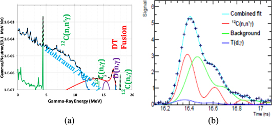
Figure 17. (a) Calculated gamma spectrum. Reprinted with permission from [96], copyright (2012), AIP Publishing LLC. (b) GRH data for a 2.9 MeV threshold from a high-foot implosion. Shown is a fast oscilloscope trace of the detector's signal over the burn duration. The fit curves result from convolving functions of gamma-ray production with the impulse response function of the detector; a Gaussian source is assumed for the carbon signal (signal ringing arises from the PMT used in the detector). Adapted with permission from [97], copyright (2012), AIP Publishing LLC.
Download figure:
Standard image High-resolution imageAs an example of typical data reduction, GRH spectra in figure 17(b) displays a least squares data fit, which decomposes the 2.9 MeV channel data into a 12C(n, n'γ4.4) signal and two backgrounds. Constraints are placed on each background contribution. Calibration with an exploding pusher target with negligible ablator and DT areal densities and the high-foot target holder determine the neutron-induced background for a given neutron yield. A contribution of less than 5% background from the T(D, γ) reaction is also taken into account. The T(D, γ) yield, extracted from the two highest thresholds, combined with its γ-ray spectrum and the detector response, determines the 2.9 MeV background. Calibration of the detector for 12C(n, n'γ4.4) has been performed in situ with an DT exploding pusher and a thin (1 cm) graphite disk. A conversion factor that transforms the time-integrated γ-ray signal from 2.9 MeV data into a total number of 12C(n, n'γ4.4) reactions was thus determined from this calibration.
The 12C gamma-ray measurements are used to deduce the areal density of the remaining hydrocarbon ablator in the stagnated fuel assembly [98]. The 12C (n, n'γ4.4) yield on a specific shot is determined by integrating the fitted signal and multiplying the result with the measured conversion factor. The ablator areal density measurement depends on the ratio of 4.4 MeV rays to neutrons. While a calibration has been performed with a known 12C areal density, the ablator areal density accuracy depends on neutron spectral analysis between the calibration shot and the measurement in question. For high compression implosions, the DT areal density modifies the birth neutron spectrum by inelastic scattering processes; this component requires a correction to the 12C (n, n'γ4.4) reactions at energies less than 14 MeV. Folding the down-scattered spectrum with the 12C (n, n'γ4.4) cross section establishes a correction of approximately 20% to the measured carbon ρR. Uncertainties from the down-scatter correction and detector calibration limit the accuracy of the ρR measurements to ±20%.
Another interesting diagnostic signature may be accessed for lower yield shots such as TH (10% D)-filled targets with neutron yields at 1012. In this case, 20 MeV γ-rays from up-scattered protons in t + p fusion reactions can be observed. These gamma rays give a clean, essentially background free signal and provide a sensitive ρR fuel diagnostic proportional to (ρR)2. This γ-ray diagnostic is complementary to some of the radiochemistry diagnostics (see comment in section 3.2.6).
Extending this general approach to energy resolved γ-ray spectroscopy in the picosecond time domain of fusion reactions or of excited nuclei in HED environments is desirable but difficult. The γ-rays with energies less than 1.5 MeV can be analyzed with high-energy resolution by means of crystal spectrometers combined with fast scintillator based detector arrays; this requires high γ-ray fluxes. For γ-rays with energies up to about 20 MeV large fast single event scintillator-based detector arrays are a possible solution. A gamma spectrum emitted from the NIF target capsule can be energy-resolved by utilizing a one-event, macro 'pixelated', detector. Such a single event detector array must be located at a large distance (e.g. 100 m) from the NIF TC; this deployment would be technically challenging.
The current GRH diagnostic is limited in both time response and energy discrimination by its large stand-off distance (6 m) to the TCC, Qualification of the LPI x-ray and prompt hohlraum-gamma background for a new GCD (GCD-3) at the Omega facility has been completed. This assembly will be mounted in a shielded well at 3.9 m, thus reducing the stand-off distance. The relative configurations of the GRH and the well-mounted GCD are displayed in figure 18. An expanded view of the well-mounted diagnostic is also provided in figure 18. An immediate improvement in the measured gamma-ray temporal response will be achieved by using a photodiode detector, lowering the present 100 ps GRH time resolution to 60 ps. In the next deployment phase, pulse dilation technology will be introduced to further shorten the temporal resolution to 10 ps for neutron yields above 1015. A third phase in the deployment of a GCD ('super GCD') has been proposed to extend the effective neutron yield range to include very low yield (1011) implosions by moving the detector to 20 cm from TCC. Substantially greater insight into ICF implosion dynamics will be obtained with these improvements. Outstanding issues such as residual kinetic energy in the fuel assembly, thermonuclear burn truncation due to material mixing, and the quantification of alpha-particle heating can be directly addressed.
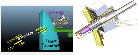
Figure 18. Schematic drawing of the existing GRH at 6 m from TCC and the recently fielded GCD-3 in a target chamber well. The proposed Super GCD position is also indicated. Right hand figure reprinted with permission from [99], copyright 2016 AIP Publishing LLC.
Download figure:
Standard image High-resolution image2.1.7. Proton Wedge Range Filter (WRF) spectrometer
Spectra of protons emitted by inertial fusion implosions are measured with WRF proton spectrometers [100–103] on both OMEGA and the NIF. The protons are incident upon a wedged aluminum filter, with thickness varying from ∼150 μm to ∼2 mm. Transmitted protons are detected with CR-39. Within a certain energy range, CR-39 can accurately measure proton energies via the track size, and by accounting for the known thickness of aluminum transited the incident proton energy is inferred [104, 105]. A spectrum is a histogram of all tracks detected on the CR-39. The WRF can measure the proton spectrum between ∼4 and 20 MeV, and for yields ≥10 on NIF.
In fusion research, 'surrogate' CH-shell implosions filled with D3He gas are used as 'mirror reaction' in place of the cryogenic DT ignition targets for measurements of symmetry, implosion velocity, and other studies. In these implosions, the D + 3He fusion reaction generates an energetic proton at 14.7 MeV. Spectroscopy of protons produced at the shock-bang time, while the dense shell is still imploding, has been used to study the implosion shock dynamics [104] and in-flight symmetry [105].
For fundamental science, the WRFs can measure proton spectra from reactions relevant to stellar nucleosynthesis and few-body nuclear physics [106]. The 3He + 3He fusion reaction, the final step of the solar proton-proton I chain, produces protons up to 10.8 MeV, which can be measured using the WRF. The T + 3He reaction, a complementary 6-nucleon system, produces protons with energies up to 12.1 MeV. The spectral shape for these reactions can be used to constrain phenomenological and ab initio nuclear theory of few-body charged-particle reactions, a topic of current research.
2.1.8. Particle time of flight (PTOF) and MagPTOF diagnostics
The time of peak nuclear production (nuclear-bang time) provides a valuable comparison between ICF implosions and simulations. The PTOF diagnostic was implemented to measure nuclear-bang times in NIF implosions using DT, D2, D3He, and T2 fuel [107].
The active element of the PTOF detector is a 200 μm thick, 10 mm diameter circular CVD-diamond wafer with gold electrodes deposited on either side. This wafer is held in a brass housing, positioned approximately 50 cm from TCC by the same hardware that positions the WRFs on the DIM (at chamber location 90, 78), and the rear surface is biased at high voltage (typically −250 V). High energy neutrons and protons produced by fusion reactions in the implosion excite electron-hole pairs when they transit the wafer, which are then swept out by the bias field, producing a current impulse. These signals are recorded as a voltage impulse by a transient digitizer and one channel of a digitizer. The timing of the observed signal trace on both oscilloscopes is absolutely calibrated with respect to the NIF optical fiducial system on periodic x-ray impulse shots, allowing the precise inference of the nuclear-bang time for an observed particle signal. Signals are forward-fit with a particle source function, which is constructed using the observed particle spectrum Doppler-broadened and convolved with the IRF measured on x-ray impulse shots. The particle time-of-flight is subtracted from the signal detection time to obtain a precise bang-time. Analysis of the primary imaging data from DIM (90, 78) provides accurate knowledge of the detector distance from TCC; total uncertainty in the inferred bang times is generally less than ±100 ps.
Due to its proximity to TCC, PTOF is uniquely capable of recording accurate nuclear bang-times using several nuclear products and at very low yields: DT-neutrons (14.1 MeV) with yields above 1.5 × 10¹⁰, DD-neutrons (2.45 MeV) with yields above 3 × 10¹⁰, and D3He protons (initially 14.7 MeV) with yields above 1 × 10⁷. PTOF is the only diagnostic capable of measuring bang-time using DD-neutrons, which are produced in surrogate implosions with D2 or D3He fuel. Uncertainty of neutron bang times is dominated by uncertainty in the detector positioning, and is typically ±41 ps for DT-neutrons and ±62 ps for DD neutrons. Unlike neutrons, protons are substantially downshifted from their birth energy by ranging in the fuel, shell, and hohlraum, such that uncertainty of proton bang times is dominated by the proton mean energy as measured by the WRFs, and is typically ±90 ps. To date, PTOF has recorded accurate bang times on over 200 experiments at the NIF.
PTOF has demonstrated the simultaneous measurement of DD-neutrons produced at compression-bang time (near the time of peak fuel compression) and the D3He-protons produced at shock-bang time (0.5–1 ns prior to peak compression, near the time of peak implosion velocity; see 'WRF' section for more information) on several near-vacuum hohlraum (NVH) implosions with D3He-gas target fill; see figure 19. These simultaneous measurements of the shock- and compression-bang time differential in indirectly-driven implosions provide uniquely valuable information on the shock propagation and the deceleration phase. Comparison of these results to simulations indicates that the fuel assembly in these subscale, high-adiabat implosions is well-understood. In contrast, a comparison of the ρR at shock-bang to radiography data suggests that the shock-bang time is not well understood in full-scale D3He-gas filled implosions surrogate to cryogenic experiments [108]. Such full-scale gas-filled hohlraum implosions produce much larger x-ray backgrounds than the subscale NVH implosions, such that the x-ray filtering required for the PTOF detector is too thick for protons to reach the detector and PTOF is unable to measure the shock-bang time using D3He-protons directly.
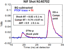
Figure 19. First measurement at the NIF of shock and compression bang times, measured by PTOF on a near vacuum, 2-shock, high-density-carbon implosion. Previous to these measurements, only compression bang times have been measured in NIF indirectly-driven implosions.
Download figure:
Standard image High-resolution imageThe MagPTOF upgrade to the PTOF diagnostic was implemented to measure the shock- and compression-bang time on full-scale implosions using the D3He-protons and DD-neutrons, respectively [104]. The design incorporates thick (1–4 cm) tungsten filtering between the PTOF detector and TCC to reduce the x-ray background by a factor of 1000x, and uses a fixed dipole magnet with peak field strength of 1 T to bend protons with energy between 6 and 16 MeV around the shielding and onto the PTOF detector. The MagPTOF has been implemented as a ride-along diagnostic on DIM (90, 78), utilizing the same detectors, cables, and recording systems as the PTOF.
The MagPTOF system incorporates a piece of CR-39 nuclear track detector surrounding the PTOF detector, allowing it to be fielded as a charged particle spectrometer. When the magnet is fielded with a slit aperture, incident charged particles are deflected onto the CR-39 with their final recorded position a function of the particle energy. The system can record protons in the energy range 2–4 MeV with a resolution of ±100 keV.
This unique capability will be valuable for spectroscopic measurements of 3.0 MeV protons from the DD-fusion reaction for both low-ρR implosions and laboratory astrophysics experiments, such as collisionless counter-streaming plasma experiments to study the Weibel instability [109].
2.1.9. Radiochemical diagnostics (RC)
The NIF RC diagnostics are based on nuclear reactions of neutrons or charged particles with detector nuclei that are present in either the target capsule or the surrounding hohlraum assembly.
Following a NIF target shot, the resultant debris products, either gaseous or solid, are collected from the chamber and analyzed via radiation detection or mass spectrometry to determine the concentration of reaction products that were produced in the capsule and hohlraum. The number of reaction products is related to the particle flux produced during the capsule implosion and is used either as a diagnostic of the capsule performance, or as a way to measure reaction cross sections.
Gaseous products are collected via the RAGS system (figure 20) [6]. The gas load from the TC is diverted through a series of turbo pumps to the first stage of RAGS where the gas is filtered to remove unwanted species and reactive gases. This procedure leaves primarily a noble gas fraction for further purification and collection. The system can be set to collect xenon or both krypton and xenon by adjustment of the cryotrap temperature. Radioactive isotopes are first analyzed on the cryotrap via in situ gamma-ray spectroscopy using a HPGe gamma-ray detector positioned above it. The gases can be subsequently transferred and frozen into a removable sample bottle, which is then subsequently analyzed using high-efficiency HPGe gamma-ray detectors or noble gas mass spectrometry. In order to determine the total efficiency for collecting reaction products from the NIF chamber, a small amount of either stable or radioactive tracer gas is injected into the chamber immediately following the shot and pumped with the gaseous products into the RAGS system. The total collection efficiency is determined by comparing the number of tracer atoms in the final gas fraction to the number injected during the shot. This efficiency is then used to extract the total number of radioactive gas atoms that were produced during the shot.
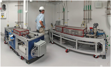
Figure 20. The 'Radiochemical Analysis of Gaseous Species' (RAGS) apparatus. The gas-load from the NIF chamber is pumped to RAGS following a shot where it is filtered to remove unwanted species (right cart) before the noble gases are cryogenically frozen and analyzed (left cart) to quantify the number of nuclear reactions that occurred during a shot. Reprinted with permission from [6]. Copyright (2012), AIP Publishing LLC.
Download figure:
Standard image High-resolution imageCollection of solid debris is performed with the solid radiochemistry (SRC) diagnostic (figure 21) [110]. The SRC consists of 2 inch diameter discs of either pure metals (tantalum or vanadium) or carbon foils mounted in holders on several DIMs [111]. Up to four discs can be fielded at 50 cm from TCC on each of three DIMs—two on the equator at coordinates 90–78 and 90–315 and one on the north pole at 0–0. Each disc has an active surface area that covers 4 × 10⁻⁴ of the 4π solid angle. In addition, a large area detector (vast area detector for experimental radiochemistry, VADER) covering about six times more solid angle than the 2 inch discs can be fielded on DIM 90–78 for increased collection efficiency [112]. Following a NIF shot, the DIMs are retracted from the NIF TC, and the SRC discs or large area detector are removed and transferred for radiation counting via high-efficiency gamma-ray spectroscopy. Depending on the reaction of interest, SRC samples may be first chemically processed to separate the material of interest from other interfering background products. Non-radioactive species are determined via mass spectrometry. Collection efficiency is determined relative to the total number of 196Au atoms collected from the gold hohlraum.
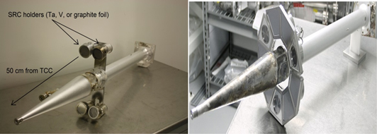
Figure 21. Solid radiochemistry (SRC) diagnostic. The standard SRC configuration (left) consists of four, 2 inch diameter collectors mounted on the end of a boom at a distance of 50 cm from the Target Chamber Center (TCC). The larger area vast area detector for experimental radiochemistry (VADER) (right) has a total surface area roughly six times larger than the four standard SRC foils combined. Left figure reprinted with permission from [113]. Copyright (2014), AIP Publishing LLC. Right figure reproduced with permission from [111]. Copyright 2015 Society of Photo Optical Instrumentation Engineers.
Download figure:
Standard image High-resolution imageNuclear reactions occur on materials that are either incorporated into the NIF capsule shell as detector atoms or materials present as part of the surrounding hohlraum assembly. After the lasers are fired, both neutrons and charged particles (protons, deuterons, tritons and alpha particles) are produced in the capsule fuel, which then interact with the surrounding detector material to produce radioactive products. These products are then collected and evaluated using either RAGS or SRC. The number of reaction products produced on any given target material depends on the location of the detector atoms with respect to the source of the particles, the distribution (density gradient) throughout the capsule shell or hohlraum, the energy flux of the particles, and the corresponding reaction cross sections. The DT fuel areal density (ρR) determines the number of primary (14 MeV) and scattered neutrons as well as charged particles (e.g., d, p, α) that induce the reactions that create the radioactive product isotopes. A large fuel ρR results in a higher probability of neutrons being scattered off of the D and T atoms to lower energies. An estimate of the ρR, therefore, can be extracted by measuring the number of radioactive products produced at lower energies in comparison to the 14 MeV neutron yield. The gold in the hohlraum is exposed during a shot to the total neutron spectrum that is produced during the implosion. The activated gold debris is typically collected via SRC and analyzed for products that are created in the 197Au(n, γ)198Au and 197Au(n, 2n)196Au reactions. The ratio of the neutron capture products, which are produced with larger reaction cross sections at lower neutron energy, to the number of (n, 2n) products, which are sensitive to the 14 MeV neutrons, is correlated to the fraction of neutrons that have been scattered to energies in the 10–12 MeV range (the down scattered ratio, or DSR) [113]. Figure 22 shows the 198Au/196Au ratio determined for a series of DT shots at NIF. This ratio provides a diagnostic for the fuel compression since the DSR is directly related to the ρR.

Figure 22. Gold ratio data measured from SRC collectors on all DT shots fired at NIF as of April 2016. The gold ratio is a measure of the 197Au(n, γ)198Au to 197Au(n, 2n)196Au reaction as determined by gamma spectroscopy of the resultant debris collected with SRC; the NTOF DSR (abscissa) is the authorized value as reported by NIF.
Download figure:
Standard image High-resolution imageWhen detector atoms are loaded in the NIF capsule, as opposed to the hohlraum, the number of reactions that occur is sensitive to the location of the dopant atoms, whether they are located in a uniform layer or have a density gradient, the symmetry of the implosion, temperature, and mix between the capsule ablator and the fuel. In addition, the range of the incident particles is also a factor. Alpha particles and deuterons have much shorter ranges than neutrons. If tracer materials are loaded at the fuel-shell interface, the observation of charged-particle reactions could provide a useful diagnostic for quantifying the amount of ablator/fuel mix. For example, if 127I were loaded in the capsule ablator, the 127I(d, 2n)127Xe reaction produces a noble gas that can be collected and quantified using RAGS. If 124Xe was co-loaded with the 127I, the ratio of the (d, 2n) reactions on the iodine to the 124Xe(n, 2n)123Xe reaction would provide a symmetry and mix diagnostic where the xenon provides both yield normalization and a measure of collection efficiency. The ratio is integrated over the peak burn (width) while uncertainties in energy and space are eliminated.
The NIF chamber is intrinsically an explosive environment, which makes collection and interpretation of debris more difficult. To interpret the measured number of collected products from loaded materials as a corresponding ρR or mix diagnostic, independent measurements of reaction cross sections are required. In addition, the debris from the capsule and surrounding hohlraum assembly are not uniformly distributed on the SRC collection plates. Therefore, the effects of chemical condensation and fractionation (separation) of volatile species must also be considered in the quantification of reaction products [114]. For the collection of small numbers of atoms, alternative methods of high-efficiency debris collection may need to be considered. This may include development of charged collection plates, or aerosolized gas-jets. Collection prototypes can be developed at accelerator facilities before implementation at NIF.
Besides providing unique mix- and fuel ρR diagnostics, RC can also potentially be used to measure unknown reaction cross sections by introducing detector materials, including radioactive species, into capsule ablators for DT shots. The burn time of a typical NIF capsule is very short, which means that short-lived nuclear states are available as target nuclei for subsequent nuclear reactions. This makes NIF potentially a unique facility for cross section measurements. In a typical accelerator irradiation, the particle flux is too low to be able to create activated species from short-lived states. The number of target atoms required to perform a comparable experiment at NIF is on order of 1016, which means that even radioactive targets are possible. Another unique feature of NIF is that the contribution from lower-energy neutrons that scatter off of the surrounding chamber materials (so-called room-return neutrons) has been shown to be negligible within the NIF capsule and hohlraum [113]. This means that neutron capture reactions measured on detector materials loaded in NIF capsules will not require large corrections to account for contributions from chamber-scattered neutrons, which is not the case for most neutron facilities.
In order to perform measurements on extremely short-lived species (half-life ∼1 min) a rapid sample extraction system would be needed to remove solid debris samples from the NIF TC for immediate radiation counting following the shot. A proposed design for such a system, the rapid access collection for experimental radiochemistry (RACER), would field a solid debris collector on one of the DIMs at a distance of 50 cm from TCC. Immediately following the shot, the sample would be dropped into a vacuum tube where it would be transported from the TC directly into the basement of the NIF facility. The sample would then be placed on a high-purity germanium detector for gamma-ray spectroscopic measurements. Based on the initial design of the RACER apparatus, the time between collection and counting is on the order of 1 min [113]. This would allow for measurement of short-lived reaction products that would otherwise not be possible based on current sample retrieval times of >2 h post shot.
2.2. Measurement of electron temperature with using MCP based gated x-ray imager
The temperature and density of the imploded core are the most important metrics of fusion plasmas. The temperature of the ions (Ti) can be inferred from the Doppler broadening of the neutron spectra [63]. Here we describe a method to infer the time history of the electron temperature (Te) by analyzing the halo of the x-ray images of the hot spot recorded with x-ray framing cameras [115].
Figure 23 shows the expected x-ray spectra from the compressed fuel of DT implosions having different Te. The lower energy side of the spectrum is determined by the absorption of the x-rays in the ablator. The photon energy of the peak of the emission is determined by both the areal density of the ablator and the electron temperature of the core. At photon energies above 15 keV the ablator is effectively optically thin and the slope of the spectra is entirely determined by the electron temperature. To infer Te from the x-ray spectrum, it is crucial to measure the amount of x-ray emission around and well above 15 keV.
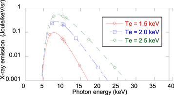
Figure 23. X-ray spectra assumed in the model.
Download figure:
Standard image High-resolution imageFigure 24 shows our experimental setup. A pinhole array of 186 pinholes, 10 μm in diameter, is located at about 100 mm from the implosion core. The nominal thickness of the pinhole substrate is 75 mm of tantalum. To protect the diagnostics from target debris, we reinforce the mechanical strength of the pinhole array by using two thick collimator plates with 150 mm diameter pinholes. Each pinhole casts an image of the core on the surface of an MCP based x-ray framing camera located at 1300 mm from the object.

Figure 24. Experimental setup of pinhole/penumbral imaging.
Download figure:
Standard image High-resolution imageIn addition, photons with x-ray energies above 30 keV penetrate the pinhole substrate and form penumbral images, a 'halo', through the 150 μm diameter collimators, around each pinhole image. Because the pinhole and the penumbral image have different spectral contents, it is possible to infer the x-ray spectrum above 15 keV from the contrast of pinhole and penumbral images. In other words, the contrast of the halo relative to the pinhole image provides the amount of x-ray emission from the core on the high energy side of the spectra shown in figure 23.

Figure 25. Lineout of x-ray image near the time of core peak emission.
Download figure:
Standard image High-resolution imageFigure 25 shows the lineout of one of the x-ray images, obtained with the MCP based framing camera, near the peak emission time of the core. The observed intensity of the halo image is about 6% of the peak of the pinhole image. Our analysis program searches for Te which produce an x-ray spectrum consistent with the observed contrast in the pinhole and the penumbral images.
Figure 26 shows a comparison between the time resolved electron temperatures, Te, inferred using this technique, represented by the squares (red), and plotted against the ion temperature, Ti, measured from the neutron Doppler broadening, using the nTOF diagnostic, on the horizontal axis.
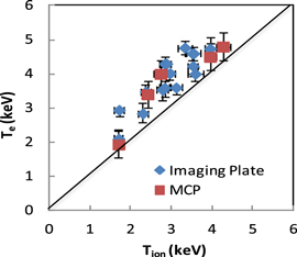
Figure 26. Comparison of Te inferred from the 'halo' of the x-ray images, red squares, and from Ross pair filters, blue diamonds, with the Ti from the neutron spectroscopy.
Download figure:
Standard image High-resolution imageThe time integrated electron temperatures, diamonds (blue), inferred from the intensity of x-ray images recorded through Ross pair filters on imaging plates are also shown [115]. The electron temperatures obtained with these two methods show good correlation with the ion temperatures measured from neutron spectroscopy. However, the inferred electron temperatures are 0.5–1.0 keV higher than the ion temperature. The difference could be due to the insufficient modeling of the spectral sensitivity of the x-ray detectors. We believe an absolutely calibrated time resolved x-ray spectroscopy can help to understand the reason of the observed difference.
2.3. Experiment design and modeling of the plasma environment
The development of nuclear diagnostic capabilities for ICF research at the NIF as described in the section below provides an essential experimental basis for basic science in general and more specifically, nuclear science research. Monitoring the nuclear DT fusion reactions requires evaluation of the neutron yield, fuel areal density, ion temperature and burn time; these diagnostic signatures quantify progress in ICF research. A wealth of shot data, and its interpretation on the basis of extensive simulations, demonstrates the maturity of the nuclear diagnostic experimental suite. The data evaluation and associated simulations guide subsequent experimental steps to improve the performance of ignition experiments [116].
The same ICF diagnostic suite can be used to acquire nuclear data. Nuclear data are of course central to developing basic nuclear science research programs in the HEDP environment. This information includes the nuclear reactions used to monitor ICF data (e.g. alpha induced reactions for alpha heating studies) relevant to fusion, and also neutron-mediated reactions of shell tracer materials, which provide diagnostic information about the DT fuel areal density. This approach to nuclear reaction studies has been validated on the basis of extensive simulations for the design of proposed experiments [117, 118]. Nuclear reaction products are collected using the radiochemical (RC) diagnostic system that enables the efficient activation analysis of solid and gaseous reaction products. Radiochemical analysis offers valuable information complementary to the neutron and gamma ray diagnostics. For example, either the naturally occurring impurities in the ablation shell or the intentional introduction of a low atomic fraction of tracer materials can provide activated materials that produce a snapshot of the average imploding fuel areal density and ion temperature. A simulation-based assessment of the approach to diagnose ignition failures on point-design cryogenic targets utilizing radiochemistry has established the feasibility of the method [118]. Using currently available nuclear reaction cross section data, modest uniform doping of the innermost ablator region provides clearly observable reaction product differences that are directly linked to implosion performance.
Under the implosion conditions relevant to ICF research, prompt nuclear reactions, such as high-energy threshold (n, 2n) reactions, are limited to the time of peak burn and thus provide an inherently timed implosion signal without recourse to an external time fiducial. On the other hand, neutron capture products accumulate long after peak burn thus sampling the late-time behavior of the implosion. Similarly, uniform tracer material in the ablation shell could provide angular information without fielding experiments along multiple lines of sight to the target since asymmetric burn conditions would be inherently imprinted along different angles. In fact, the routinely fielded FNAD (see above) already provides valuable information about anisotropy in the stagnated shell using zirconium foils mounted on the NIF chamber wall without recourse to additional dopants. Anisotropic activation within the fuel assembly yields information complementary to the FNAD detection of outer shell non-uniformity. Physical phenomena critical to burn conditions, such as charged particle deposition lengths, will have distinctive nuclear reaction signatures and provide data difficult to obtain otherwise.
The experimental design studies for ICF research also include the identification of a potential mix diagnostic since ablator mix into either the hot core or the cold DT fuel layer is a likely failure mechanism. In simulations, realistic high mode surface imperfections were imposed upon the exterior of the ablation shell that were large enough to introduce some material mixing into the fuel but did not prevent robust burn. For example, 1016 atoms of 124Xe and 136Xe could be loaded at separate radial locations in the ablator. The relative activation of the (n, 2n) products may then be directly related to the amount of ablator material mixed into the DT fuel layer. In contrast, the well-known technique of plasma x-ray spectroscopy to quantify mix fails in the DT fuel layer since the relevant tracers are too cold to emit x-rays [119]. Hence, nuclear-based mix diagnostics probe otherwise inaccessible portions of the stagnated fuel assembly.
Attempts to provide a covariant data analysis utilizing the nuclear diagnostic data to describe the dynamics of the hot spot conditions in ignition experiments demonstrated the limitations of the present nuclear and plasma spectroscopy diagnostic capabilities [117]. This approach had been validated with radiation-hydrodynamic code simulations. It seems however that a correlated analysis should be the path forward for future analysis algorithms utilizing the extensive simulation capabilities at the NIF and provided sufficient high quality experimental data can be obtained. In general, these highly developed simulation and design capabilities can be applied as well to nuclear reaction studies for basic and applied science, especially to characterize the burning core plasma conditions. A variety of nuclear science experiments utilizing established ICF platforms and simulation applications are described in section 3.
As an illustrative example, the synergy between ICF research-driven nuclear diagnostics and application to nuclear science research is most obvious for the radiochemical analysis of nuclear reaction products produced inside the target capsule: a sufficient amount of a tracer element, purposely located at the DT ice/ablator interface will provide an ablator/ice mix failure mode diagnostic by measuring the ratio of neutron to charged particle induced reactions including mix ranging close or into the gaseous hot spot. The accurate quantification of reaction products from tracer elements together with the measurement of the neutron flux will give reaction rates of interest (e.g. for nuclear astrophysics). The uncertainty of the RC analysis is largely determined by the errors for the collection efficiency of the reaction products, fractionation, counting efficiencies and background effects. In turn specific reactions (e.g. see alpha reactions in section 4) may serve as monitors for implosion performance. It should be noted that a major experimental issue is the quantification of contaminant tracers in the ablator shell material and materials surrounding the target which add background noise. Simulations were carried out to understand where a radiochemical technique would most effectively complement or, by itself, provide information for ignition failure.
The production of radioactive nuclei from a small number of tracer nuclei implanted in a NIF capsule is given by the convolution of the areal density, ρR, neutron flux, Φn, and cross section, σ,

where the integration is performed over a relevant capsule radius, rmax, energy range, Emax, and reaction time, δt.
Since higher energy neutrons move away from the capsule so quickly (5–100 ps), the time integral can be approximated by inserting areal density and flux averages near peak burn time

If two nuclei are co-loaded (in a chemical compound for example) and the same reaction on both nuclei is assumed then their spatial integral and ρR will be identical and the production number ratio can be evaluated

Thus the measured ratio of two separately detected products will provide information about the neutron flux; the accuracy will be largely controlled by errors in the assumed cross section. Conversely, if the neutron flux were known, then this ratio would provide experimental constraints upon the cross-section data.
A recent proposal (see section 4) to investigate plasma screening effects upon thermonuclear reaction rates provides another example of using established NIF implosion platforms for basic nuclear physics research. Specifically, the number of 7Be atoms from the thermonuclear reaction 10B(p, α)7Be would be determined by mass spectroscopy from capsule material collected on the existing SRC detectors. Two NIF platforms were identified as suitable candidates from previous shots for this study: an indirect drive exploding pusher (IDEP) and an HDC 'Symcap' Symmetry Capsule. The IDEP burning core conditions are quite hot, with peak temperatures exceeding 20 keV, but have small fuel areal density. HYDRA simulations (figure 27) of an IDEP filled with 10B-enriched di-borane indicated that sufficiently robust 7Be production would occur, thus providing an initial test of the collection and measurement capabilities. Note that the high peak ion temperature produces the desired 7Be signal during the initial part of the thermonuclear burn but most of the thermonuclear fusion neutron yield arises later in the burn when the hot core density has increased. Thus the neutron-based diagnostics will not represent the plasma conditions during maximum 7Be production. However, the full suite of implosion diagnostics will severely constrain the plasma conditions throughout the implosion so that the entire burn history can be accurately characterized.

Figure 27. Production rate simulation results for 10B(p, α)7Be production plotted as a function of time in an IDEP experiment (blue curve). Other thermonuclear fusion reactions are also plotted: the 7Be production occurs in a nearly uniform temperature and density plasma regime (25 keV and 0.40 g cm−3). Note that the nTOF Tion will no longer represent the conditions of maximum 7Be production.
Download figure:
Standard image High-resolution imageAnalogous simulations for an HDC Symcap were then used to determine 7Be production under lower core temperatures but substantially increased fuel areal density. Small amounts of deuterium and tritium were added to the di-borane gas fill to act as burning core temperature and density diagnostics. Under suitable conditions, 7Be production was estimated to be 105 atoms, which is a challenging, but feasible, experimental measurement. Although many experimental details remain to be demonstrated, this approach suggests yet another path to using established NIF implosion platforms and nuclear diagnostics to study nuclear processes in a hot, dense plasma environment.
3. Present research efforts: data analysis, evaluation and results
3.1. Data analysis and evaluation at the NIF
The NIF data and its analysis is organized around shots. Each shot design generates a set of specifications covering the laser, target, and diagnostic requirements. Pre-shot calculations may also use data from previous shots to optimize capsule performance, especially shots specifically designed to provide important input information. This approach also leads to the idea of experimental 'platforms'—that is, an archive of shot performance metrics that guides shot performance for newly proposed experiments.
The analysis of diagnostic data provides the information to perform post-shot analysis of the platforms to compare with the pre-shot calculations. The importance of the post-shot analysis is particularly acute when variations in laser and target performance approach the levels of the physics variations in the experiments.
An experimental campaign consists of several shots for which the shot-to-shot variations also become important. While laser performance is repeatable to better than 5%, the nature of the experiments may be sensitive to even smaller variability, especially comparing many shots. In addition, the targets are destroyed in each shot making them unavailable for post-shot examination.
Shot rate and shot types are also limited by operational considerations. Some sets of diagnostics are sensitive to high neutron doses and cannot be present during high yield operations. High power shots also affect the laser operational readiness that limits both the rate and the total number of shots available. For many nuclear experiments requiring high neutron yield the total number of shots possible is of order 1000, (one per week for the standard DOE facility lifetime of 20 years, the system performance to date is 16 DT yield shots per year). These limits put additional requirements upon nuclear experiments that are very different from traditional nuclear experimental facilities and require new approaches to data analysis.
The data analysis and evaluation environment at NIF is outlined in a series of articles [120–125]. Figure 28 shows the data analysis system block diagram. The Shot Data Analysis Engine performs initial analysis at varying levels of sophistication for the diagnostics deployed for a shot. All shot data and analysis results are stored in the NIF Data Archive and accessed by data analysts through the Data Visualization Tools which includes both a data visualizer as well as a set of utilities that allows automated access to the shot data and diagnostic calibrations for post shot analysis.
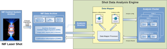
Figure 28. A block diagram of the NIF shot-data analysis system.
Download figure:
Standard image High-resolution imageIn addition to measuring the parameters of direct importance to nuclear experiments, there is the additional requirement of characterizing the plasma in which the nuclear reactions take place. The role of platform development for these experiments is to develop the various plasma diagnostics and undertake a set of calibration shots for the measurements.
The uncertainty quantification becomes more complex since it is essential to identify not only statistical and systematic uncertainties, but also to differentiate between shot independent and shot-to-shot uncertainties. Further model uncertainties may become an important aspect of the characterization of the results, especially where models are required for calculating the plasma conditions, extending the results of supporting shots, and models of particle propagation through the target and into the detectors.
The paucity of shot opportunities stresses the importance of maximizing the physics content of each shot; part of this can be accomplished by experimental design that includes strategies for mitigating these uncertainties. An example is provided in the following section of the trends in ICF capsule performance for the parameter traditionally identified as the ion temperature, Tion, defined as the variance of the neutron kinetic energy spectrum. The estimated uncertainty of this measured quantity includes both systematic and statistical uncertainties. A detailed, sophisticated analysis of the nToF spectrometers resulted in both the redesign of the spectrometer system (to improve performance) and the ability to separate the various components of the measurement uncertainties. The comparison of the Tion derived from the spectrum of DT neutrons compared to the DD neutrons excludes the hypothesis that these are the same, a conclusion that is not supported without the refined uncertainty analysis. The combination of high neutron yields, precise and accurate diagnostics, and analysis which includes uncertainties helped reveal aspects of the implosion not otherwise accessible.
Another strategy that has been used in large nuclear physics experiments (and in high energy physics) integrates the analysis of the entire diagnostic suite. The resulting analysis software framework would incorporate all the information required to extract physics, including all supporting shot data (which could be from other shots) as well as the results of simulations and calculations. The utility of a fully integrated analysis makes use of the correlations among the various diagnostics and constrains the underlying physics models. However, the complexity of the physical information generated by each high yield shot, which currently produces of order 1016 neutrons (and a huge number of associated quanta) will require simulation techniques that can provide a high-fidelity prediction of the numerous diagnostics and a methodology for handling the huge output stream of the calculations.
3.1.1. ICF specific data analysis and simulations
NIF experimental data are currently limited by inadequate sampling of important spatial and temporal aspects of the critical stagnation phase. Consequently, the existing data must be augmented by simple physical models and more realistic radiation-hydrodynamic simulations to guide post-shot analysis and optimization. Interpretation of a particular observable, or better yet, a collection of observables, requires context provided by physics models of varying sophistication. Due to the complexity and cost of any individual implosion experiment, it is critical to the success of the ICF effort to have reliable, validated models. The most highly developed NIF simulation model to date is that provided by the radiation-hydrodynamic code HYDRA. Its application to experimental analysis will be highlighted below [126, 127].
Before an experiment, pre-shot simulations of the nominal experimental conditions are performed to set our expectations for observations—x-ray brightness, neutron yields, spectral widths, etc. To do this, we simulate not only the implosion physics, but also the detailed output from diagnostics. Our principal numerical diagnostics include synthetic neutron spectra, neutron yield histories, neutron images, and spectrally and time resolved x-ray images, all along multiple lines of sight. Such predicted pre-shot observations are accurate enough to set instrument settings that capture high quality data to avoid mistiming of streak diagnostics or saturation of image and yield diagnostics.
However, no experiment has initial conditions that correspond exactly to the specified pre-shot conditions, and real experimental data almost always diverges from pre-shot predictions to some extent. Target and laser performance can vary within allowed tolerances, and the x-ray drive is difficult to control and monitor. Hence, it is essential to capture the effects of these irreproducible variations. Our detailed metrology of targets and laser delivery give us the necessary measurements to correct our pre-shot simulations for the as-delivered fluctuations encountered during the experiment. These corrected simulations, called post-shot simulations, close a portion of the gap between pre-shot expectations and experimental observations. Yet, differences remain. The simulations are not perfect models of the experiments, and their shortcomings provide us with clues to essential physics that is not captured or is captured incorrectly in our code tools.
Post-shot designers work to tune post-shot observables to the experimental truth. While we know well the time history of laser light delivered to the hohlraum, multiple physics processes alter the temporal and spatial distribution of this energy. Laser light may be scattered by laser–plasma interactions, absorbed laser light is re-emitted as x-rays, and the x-ray drive couples through ablation to capsule hydrodynamics. Anywhere in this conversion chain uncertainties and inadequacies in our models may lead simulations to produce stagnated hot spot conditions that differ from experiments. Designers then make ad hoc adjustments to the driving radiation source to bring the simulated stagnation conditions and associated synthetic diagnostics into consistency with experiments. These adjustments are not intended to provide the physical reasoning for how the laser-hohlraum-capsule coupling ended up the way it did, but rather to highlight the timing and magnitude of driving discrepancies for which we must seek physical explanations and hypotheses. In other words, the specific type and magnitude of the applied corrections are a measure of how well we match certain experimental details and a guide to further model improvement.
This process of tuning post-shot simulations is difficult, and requires expert judgement and scientific intuition. Post-shot designers have at their disposal many adjustable parameters. These parameters include laser powers at several epochs in the laser pulse, typically 5, and on two independent laser cones. Varying these parameters entails at least a ten-dimensional parameter space to find a better match to data throughout the implosion. The process requires large investments of human time, is often inefficient, and represents a sort of iteratively greedy search for a detailed simulation match to the data.
We choose to take a complementary approach. Rather than invest large amounts of human time guiding the search for imploded plasma conditions that match experimental diagnostics, we can invest computer time to scour parameter space more thoroughly. To do this, we cover the chosen parameter space with thousands of simulations. If this sampling is sufficient, we will find the simulation that most closely matches the experiment, within the variation allowed by the chosen parameters. In addition, we find the family of simulations that forms a neighborhood around the experimental data. Whereas a single post-shot simulation provides a single set of sufficient conditions to match experiment, the ensemble approach provides a notion of sensitivity by capturing the breadth of variations that might also give near matches to experiments.
The ensemble technique provides additional advantages. While our experimental data is very sparse—about 85 cryogenic experiments over 6 years, the ensemble data captures predicted trends over a wide range of parameter space. We capture this variation using a sophisticated fit, or surrogate, that returns an observable value at all points throughout parameter space. This surrogate, then, gives us insight into the sensitivities and topography of observable response as we move through parameter space.
An important example of the utility of this approach arises in the analysis of the achieved thermodynamic conditions in the stagnated assembly. The nTOF diagnostics report a signal width variance that is directly related to the burn-averaged core temperature. Simple analytical models suggest that this burn-averaged temperature cannot exceed approximately 4.2 keV if ignition is not achieved. This limit marks the transition temperature at which alpha-particle energy deposition overcomes radiative loss leading to ignition. On several occasions, the nTOF diagnostics have reported large variances suggesting that this thermodynamic temperature has been exceed in the burning core. Given this important discrepancy, large simulation ensembles were employed to determine the fidelity of the analytical model results.
NIF cryogenic layered implosions have sufficiently high yields to make a comparison of the measured apparent ion temperatures for both DT and DD fusion possible. Naive expectation, and 1D Hydra simulations indicate that the ion temperatures should be the same within the known reactivity temperature variation. The observation is that as the ion temperatures increase, the DT temperature increases more rapidly than the DD temperature.
Simple models indicate that unphysically large velocity variance is required to match observed thermal ion temperature excursion.
The results of a large set of HYDRA-2D simulations including the range of capsule performance congruent with the conditions of the experiments results in features with a DT and DD ion temperature dependence similar to the experimental observations. The inclusion of the experiments' systematic errors shows a statistical agreement between the model and the data (figure 29). This agreement demonstrates that the inclusion of realistic temperature gradients, temperature time dependence and fuel flow velocities can be essential in providing a physical interpretation of the apparently confounding observations.

Figure 29. Comparison of HYDRA-2D simulations and experimental data.
Download figure:
Standard image High-resolution image3.1.2. Nuclear background simulations inside the NIF target bay
The NIF diagnostics must be able to operate properly during several types of shots with varying neutron yields. Components like CCD cameras and several electronic devices are sensitive to the neutron and gamma backgrounds experienced during shots. Fusion neutrons generated by fuel burn and secondary neutrons resulting from the fusion neutrons interaction with structures present inside and outside the TC contribute to the neutron background. Inside the TC, neutrons interact with the Cryogenic Target Positioner, the warm Target Positioner, and three DIMs. Neutrons also interact with the stainless steel first wall panels, aluminum TC, gunite shield, port covers, and the FOAs. In the meantime, gamma-rays induced by neutron interactions with different structures inside and outside the TC contribute to the gamma background. To simulate the expected backgrounds at different locations, a detailed MCNP [128] model has been developed for the NIF facility. The model includes most of the major components inside the TC and the major diagnostics and structures inside the Target Bay. The detailed Target Bay model is shown in figure 30(a).

Figure 30. (a). MCNP model of the Target Bay. (b). Two-dimensional view of the MCNP model at the Target Chamber Center.
Download figure:
Standard image High-resolution imageThe Target Bay model has been utilized in the simulation of expected neutron and gamma fluence throughout the Target Bay. The analysis utilized a D–T neutron source spectrum that is expected from a successful ignition target. The neutron source is modeled as a volumetric source filling the hohlraum. The neutron cross-section data were taken from the ENDF/B-VII cross-section data library [129]. Neutron and gamma fluence maps are created for each of the Target Bay floors. A Cartesian mesh size of 30 cm × 30 cm × 30 cm is used to create the maps. To reduce the statistical error associated with the simulation, particle splitting and Russian roulette are used throughout the geometry. The typical statistical error associated with the calculated neutron flux inside the Target Bay was <10%. In addition; radiation damage to electronic devices in terms of dose to silicon has also been calculated for large number of locations inside the Target Bay. These data are being used to provide options for shielding of critical diagnostics and electronics devices to ensure that high precision measurements of neutrons and gammas will be possible up to a 20 MJ yield (7.1 × 10¹⁸ neutrons/shot). During a shot the highest level of radiation is expected near the TC's waist at 7.01 m (23'0'') above ground level. The TCC is accessible through the 5.33 m (17'6'') floor level. Diagnostics and other sensitive components located outside the TC at this floor level experiences the highest level of radiation exposure due to neutrons streaming out of the TC through the large number of diagnostics ports located near the chamber's waist. Figure 30(b) shows a two-dimensional view of the Target Bay's MCNP model at the waist. In this view all the positioners and DIMs are inserted inside the chamber during the shot.
The simulated fluence and dose maps are continually used to predict the background signals as a function of the neutron yield at different locations inside the TB. Figure 31(a) shows the expected neutron fluence values during a 20 MJ shot. The neutron fluence shown in the figure represent contribution from all neutron with energies >100 keV. Contribution from neutrons with energies <100 keV was ignored since, at this low energy, neutron contribution to energy deposition and radiation damage to electronics is minimal. As shown in the figure, very high neutron fluence >1013 neutrons cm−2 is expected inside the TC during a 20 MJ shot. The fluence outside the chamber ports and in line-of-sight with the TCC is ∼1012 neutrons cm−2. Fluences at locations shadowed by the chamber's gunite shield are lower by an order of magnitude. It is also important to note that when target positioners and the DIMs are inserted inside the chamber during a shot, they provide self-shielding to components located outside the chamber.
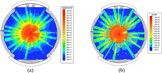
Figure 31. (a) Neutron fluence during a 20 MJ shot near the Target Chamber Center. (b) Neutron dose during a 20 MJ shot near the Target Chamber Center.
Download figure:
Standard image High-resolution imageTo identify the risk to sensitive electronics, another set of maps showing the expected dose to electronics in term of Gy (Si) were also created. Figure 31(b), shows the expected neutron dose values during a shot near the TCC. A high dose of 104–105 Gy is expected near the target (near TCC). The dose drops to 10–20 Gy outside the TC (in the line-of-sight) and to ∼1–2 Gy behind the chamber's gunite shield. Similarly, two more additional sets of maps were created for the simulated gamma fluence and gamma dose throughout the Target Bay. Figures 32 and 33 show the maps generated near the TCC.

Figure 32. Gamma fluence during a 20 MJ shot near the Target Chamber Center.
Download figure:
Standard image High-resolution image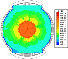
Figure 33. Gamma dose during a 20 MJ shot near the Target Chamber Center.
Download figure:
Standard image High-resolution imageAs shown on the figures, neutrons interacting with the gunite generate a large number of gammas outside the chamber. Even though the levels of fluence and dose generated by gamma exposure is somewhat similar to neutron exposure, the impact of each on damage to electronics is quite different. Dose due to neutrons with energy greater than 4 MeV is the major source for expected permanent damage to electronics. However, gamma dose could be an important background contributor to specific diagnostics. Figure 34 shows the calculated dose per unit fluence as a function of neutrons energy and for a 1 MeV gamma source.
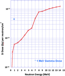
Figure 34. Dose to Si as function of neutron energy.
Download figure:
Standard image High-resolution imageThe simulated fluence and dose maps are used to identify radiation susceptible components based on their known radiation hardness. Such components are tested to a fluence greater than that a component would experience during operation. The testing consisted of component irradiation using a 60Co gamma source and accelerator-based irradiation using a 14 MeV neutron source. The Edwards Accelerator Facility located at the Ohio University was used for component testing [130]. Testing of Multiple CCD and CMOS cameras, x-ray generator controllers and digital oscilloscopes indicated that most digital components will suffer from upsets and loss of data at a 14 MeV fluence of 1–5 × 10⁸ neutrons cm−2 or a dose of 1–5 mGy. The tested components started to fail at a fluence of 1–5 × 10⁹ neutrons cm−2 or a dose of 10–50 mGy. These results indicated the need for shielding some of the vulnerable components during high yield shots or limiting their use to a lower neutron yield. Predictions for the survivability of tested components are derived from the simulated dose maps and component tests results.
3.2. Research results and status
3.2.1. The neutron flux energy spectrum from DD and DT fusion reactions
The neutron diagnostics (nTOF, MRS, NIS, NAD) provide the data for the understanding of the overall neutron energy spectrum and the dynamics of the fusion reaction volume in the ICF DT fusion reactions [73]. The nTOF diagnostic fielded at different lines of sights and complementary NI provide key diagnostic information of the symmetry and shape of the fusion burn volume. The data acquired from these instruments allow quantifying the yield and peak shape and burn volume dimensions in comparison with 3D simulations. This also characterizes the NIF as a unique high brightness neutron source for studies of neutron induced nuclear processes and cross section measurements in a HEDP. The understanding of the neutron spectra and consistent simulation of the plasma conditions are key to neutron induced reaction studies. This enhanced understanding in turn will also guide the design of experiments utilizing hot (keV), high density plasmas for non neutron producing nuclear reaction and cross section studies. The evaluation of neutron induced cross section measurements requires a quantitative understanding of the background from room return. First measurements show that the NIF conditions provide for target configurations at TCC in an environment almost free from room return. In the following, key observations from neutron spectrum measurements are discussed.
An ICF DT implosion experiment produces primary neutrons, down-scattered neutrons as well as neutrons from various secondary and tertiary scattering processes within the hot-spot and remaining cold fuel. A typical neutron spectrum is composed of a primary DT peak at 14.1 MeV, a clean down-scattered spectrum between 10 and 12 MeV, a DD neutron peak at 2.45 MeV, and high energy (15–30 MeV) neutrons produced from up-scattered D and T undergoing in flight fusion reactions. The reactions contributing to neutron production are listed in table 1 in the introduction.
The position and shape of the DT and DD neutron production peaks give insight into the temperature and velocity distributions of the hot-spot [131]. Measurements of the tertiary neutron spectrum above 15 MeV, which is on the order of 10−6 relative to the primary DT fusion neutrons, is challenging due to their low intensity and interference from background γ-rays being produced by 14.1 MeV neutrons along their flight path. The spectrum of those tertiaries provide can provide additional information about areal density and stopping power models, which is crucial for understanding contributions of alpha heating to the overall yield of the shot. Activation materials (Tm, Bi) with thresholds above 15 MeV for (n, xn) reactions, are used to verify the tertiary neutron yield.
The DT and DD fusion neutron peaks are simultaneously observable with the nTOF detectors; the continuous TT neutron spectrum (0–9 MeV) is dominated by the down-scattered neutrons from the primary DT fusion neutrons (figure 35).
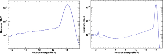
Figure 35. Neutron energy spectrum around the DT peak for NIF shot N150420-001 as measured by an nToF detector (left) compared with a Hydra simulation (right). Note that the 'wiggles' in the energy region below 13.5 MeV are de-convolution artifacts rather than actual variations in the flux.
Download figure:
Standard image High-resolution imageThe nTOF diagnostics measures the peak width of the DT and DD fusion neutron peaks, which relate to temperature and flows in the plasma. It also allows determination of the ratio of down-scattered neutrons relative to the un-scattered flux, which is directly related to the areal density of the cold fuel. Measured shifts in mean peak energies determine the magnitude of bulk motion of the burning fuel [74]. The NAD diagnostics serve to calibrate the neutron yield of the nTOF detectors. Additionally, they provide an activation profile using multiple locations around the TC allowing inferring a combination of ρR distributions and bulk motion. On average, measured yield, ion temperature and down-scatter fraction from the independent MRS, NAD and nTOF diagnostics show agreement [73]. The availability of measurements in several lines-of-sight provides quantitative information for implosion symmetry studies on single shots [132, 133].
The neutron energy in the lab system is obtained from the reaction kinematics as:

The equation describes the observed energy of a neutron resulting from a single DT fusion reaction. The first term is the neutron energy in the center of mass system (CM) expressed as a function of the kinetic energy K available in the CM system and the resulting Q value of the D + T → α + n reaction and the masses of the particles. The second term accounts for the neutron energy change from CM system into the lab system, with pn being the neutron momentum vector in the CM system and vcm the velocity vector of the CM system relative to the lab system; the reaction kinematics is depicted in figure 36. The energy obtained from the relative kinetic energy K is distributed along the Gamow peak of the reaction, with the most likely reaction energy K being ∼5 kT for a 3 keV temperature. The position of the DT peak depends thus on drift velocity and thermal motion of the hot-spot. The center of mass drift velocity of the reaction (burn) volume, the relative kinetic energy of the fusion reactants and the scattering of neutrons in the peak and outside the peak region by the compressed fuel, affect the neutron peak in the spectrum [131].
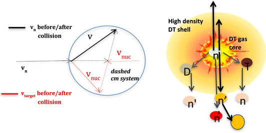
Figure 36. Reaction and scattering kinematics.
Download figure:
Standard image High-resolution imageThe DT peak is a superposition of 14.1 MeV neutrons from the fusion reaction in the reaction volume in the hot spot and neutrons scattered in the dense DT fuel (see figure 36). Fits to the data from reaction volume include the ρR induced down-scattered neutrons to correct for their effect on the width of the peak. Since the energy, K, is similar for both DD and DT reactions, the neutron energy shifts for DD and DT are likewise similar but the fractional increase is 6 times more for DD; this difference implies that the shift in the energy peak due to temperature is much smaller for DT than it is for DD. The actual width of the observed neutron peak depends thereby on a combination of plasma temperature and flows.
A simple model for the analysis of NIF shot data assumes a single temperature of the burn volume and a single overall motion. In this case, the width of the peak depends only the temperature but the peak position depends on a combination of temperature and motion of the hot spot. A more realistic assumption is that there are multiple burning regions which all have different temperatures and velocities. In this case the superposition of plasma flows and temperatures affect both the width and shift of the neutron peak, which can be described as an observed 'temperature' with kTapp = kT + (mn + mα) [62] in which
  represents the variance of the plasma flow velocities, k is the Boltzmann constant and mn and mα are the masses of the neutron and alpha particle produced by the reaction.
Since mα is replaced with m3He in the DD fusion process, the velocity field broadens the DD peak differently than the DT peak. It is indeed observed that for many cryogenic shots the DT peak has a higher apparent temperature than the DD peak. The presence of a variance in the velocity field indicates that the burning plasma is not stagnant; however, attempting to use the DD and DT apparent temperatures to deduce a thermal kT gives an unrealistically low temperature [134], indicating that the difference in DD and DT temperature cannot be explained by velocity variance alone. There are several other factors contributing to a temperature difference in DD and DT reactions: given a temperature distribution, one can only obtain a neutron yield weighted average temperature. Since the DD and DT reaction rates have different temperature dependence the weighting in the average is different. Also, D and T ions may be at different temperatures and the down-scatter losses are different for DD neutrons compared to DT neutrons.
In addition to the peak broadening due to the variance of the velocity field, the mean of the velocity field causes an energy shift of the neutron peak position. A model using the apparent temperature to calculate the mean energy of the fusion peak according to [135] allows the computation of hot spot plasma (HSP) bulk motion from the nTOF data. Each nTOF detector measures the projection of the velocity vector along its line-of-sight; using the data from at least three detectors a velocity vector can be reconstructed. The nTOF data from the high foot campaign allow to infer HSP (fluid) velocities from Doppler shifts between <30 and 60 km s−1 with half of them >60 km s−1. The HSP velocities inferred from x-ray framing cameras are consistent with the nTOF data. The cause for the HSP (bulk) velocities is not fully understood and it might be a combination of drive asymmetry, ice layer asymmetry, fill tube-jetting, localized oxygen concentration or asymmetric mix/flow of the ice layer fuel into the HSP. The nTOF data are supported by the activation asymmetries measured with the FNADs. Shots with intentional drive asymmetry (P1) showed HSP velocities of the expected magnitude. The FNADs show clear evidence for the strong drive directional dependence of high DT ρRs in agreement with simulations.
A more general description of the neutron spectrum uses the moments of the spectrum and their related cumulants [131] where the first cumulant (mean of the spectrum) relates to the position of the peak due to temperature and HSP bulk motion. The second cumulant, the variance of the spectrum, is designated as the apparent temperature above, which is a yield weighted average of different fluid elements having varying velocities and temperatures. The 3rd and 4th cumulant, skew and kurtosis respectively, give additional insights into the temperature and velocity distributions. This analysis should be done on the neutron momentum spectrum, since a single temperature is most Gaussian like in neutron momentum space, allowing skew and kurtosis to show the deviation from the single temperature case. A theoretical analysis of the neutron spectrum in the two-product thermonuclear (DT, DD) fusion, including effects from a distribution of fluid elements at different temperatures and velocities, is given in [131]. The spectrum shows a down-shift in energy of the centroid energy of the neutron peak for non-igniting NIF-implosions in which the burn occurs mostly during the implosion phase. The analysis furthermore concludes that kurtosis and skew should be universal features of neutron spectral peaks. Measuring the skew and kurtosis of the birth spectrum is complicated by the presence of the down-scattered neutrons and the need to know the IRF extremely well. Current efforts focus on improving the IRF. If skew and kurtosis are measurable, it will allow determining the effect of successive moments of fluid temperatures and velocities on the peak shape in the momentum spectrum. The peak shape features should be distinctively different for the ignition and non-ignition case [131].
3.2.2. The 3H(t, 2n) 4He reaction analysis
A new study of the neutron spectrum from low energy T(T, 2n)α reactions utilizing T-filled fusion targets at the NIF has been reported [136]. The spectrum provides information about interactions among final-state particles and the T(T, 2n)α yield, which is important in ICF experiments studying hydrodynamic mix [137]. The particle spectrum results from three-body decay and is sensitive to different breakup mechanisms. Large uncertainties have remained in the measured spectrum at low reaction energies (Ec.m. < 100 keV), due to a shortage of accelerators with tritium beams, and disparate accounts of its underlying breakup processes exist [138–141].
The spectrum from the T(T, 2n)α reaction has been described previously by statistical and/or sequential processes. Sequential decays proceed through intermediate states formed by n–α (5He) or n–n (correlated di-neutron) interactions. For transitions made through the 5He state, the neutrons emitted first are spread over the decay width of the intermediate state by energy-momentum conservation. Discussions in the literature of sequential decay through 5He have not included interference effects arising from a final state with identical fermions. As reported in [136], the sequential decay process was formulated within the R-matrix framework [142], where the necessary interferences could be incorporated. The modeled spectrum revealed a substantial change arising from anti-symmetrization.
Wong et al [143] determined from their measured neutron spectrum at Ec.m. = 250 keV that 70% of decays went by correlated di-neutron emission, with the remaining strength divided between the ground (20%) and first-excited (10%) states of 5He. As stipulated in their paper, the branching ratios were directly tied to an assumption of a strong di-neutron channel.
A previous work [141] has claimed to find no evidence of n–α interactions in the spectrum; the missing strength was explained by an energy dependence in those channels. To address this controversial issue, the ICF type DT implosion of a tritium-filled capsule was combined with the time-of-flight technique to show clearly a peak corresponding to the ground-state channel of 5He at low energies.
Using time-of-flight detectors, an yield-weighted ion temperature of kBT = 3.3(3) keV (or an effective energy of E = 16(1) keV) within the burn volume was extracted from thermal broadening of mono-energetic (14 MeV) neutrons produced by the T(D, n)α reaction. A neutron yield more than 1013 was produced over the ∼200 ps duration of the thermonuclear reactions, affording excellent statistics and timing. The neutron spectrum was recorded by two 10 cm × 5 cm xylene scintillators, positioned over 20 m from the TCC along separate lines of sight. Detectors were operated in current mode and their signals were digitized with 1 GHz oscilloscopes. Interpreting current mode data requires knowledge of the impulse response functions (IRF) from detectors. As the light decay time of the scintillator is rather insensitive to particle type, short pulses (100 ps) of x-rays have been used to measure the IRFs. Measurements have also been performed with capsules containing a 3:1 ratio of deuterium-to-tritium. These data serve to establish the neutron-induced background from residual deuterium in the capsules, and show a relatively flat baseline several decades below the preceding T(D, n)α peak (figure 37).
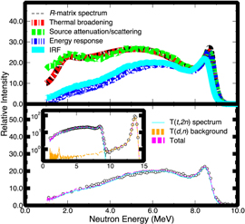
Figure 37. Comparison between the modeled spectrum (top) and data (bottom). As discussed in the text, the R-matrix spectrum must be corrected for the detector response before comparison with the data. Figure reprinted with permission from [136], copyright (2013) by the American Physical Society.
Download figure:
Standard image High-resolution imageIn the analysis, the modeled R-matrix spectrum was fitted to data from both detectors simultaneously. This method increases the neutron statistics while averaging over systematic differences between setups. Within the fitting algorithm a trial spectrum was first thermally broadened, then adjusted for source attenuation/scattering and light production. Next, for each detector, the modified spectrum was transformed from energy into time of flight and convolved with an IRF (figure 37 top spectrum) A χ2 minimization of the resulting spectrum to data determines free parameters with the MINUIT2 package [144].
Digitizer noise from scopes represented the main source of statistical uncertainty in the data. Fluctuations due to neutron statistics were much smaller, as ≈106 events were recorded within the region of interest. Systematic uncertainties have been investigated for ion temperature, source attenuation/scattering and light production. Separate analyses were undertaken for each systematic error at its 1σ deviation leading to a total error of 16%. Branching values for the 3/2− and 1/2− partial waves determined from the procedure were 29 ± 16% and 71 ± 16%, respectively. Note that the interference between partial waves is found to have little effect on the branching ratio. While differences between the fitted curve and data appear in several locations, the model describes the main features in the spectrum quite well, particularly in the region of the spectrum that is least susceptible to systematic errors, E ≤ 4.5 MeV.
New spectra from ICF experiments with enriched tritium targets have been measured using the NIF. These measurements provide conclusive evidence for n–α interactions in the 3H + 3H neutron spectrum produced by thermonuclear environments, through the first direct observation of a neutron peak from transitions via the ground state of 5He. A description of the data was obtained with an R-matrix model that accounts for the coherence between intermediate states and fermion symmetry. No previous group reporting the spectrum has considered these interferences, although as shown in a letter [136] their effects are substantial. Fits of our model to the spectrum have shown a large contribution from the 1/2− partial wave in 5He, as opposed to the dominant role assigned to either correlated di-neutron emission [143] or statistical decay. Future work is planned on understanding the neutron spectrum using new di-neutron calculations and/or sequential s-wave emission that take interference effects properly into account. We acknowledge the limitations of this analysis since it represents a two-body approximation to what is strictly a three-body problem, and hope these new data improve evaluations of fusion experiments and encourage further theoretical work.
3.2.3. The interpretation of three-body final states using R-matrix theory
The ICF environment supplies a unique opportunity to study the particle energy distributions of three-body final states, as the particles may emerge from the low-mass plasma with very little energy loss. In addition, the ICF facilities at NIF and OMEGA have the capability of working with tritium, an initial-state reactant in several interesting and important reactions yielding three-body final states.
For example, the neutron energy spectrum from the T(T, 2n) α reaction has recently been measured at NIF at an effective Ec.m. of 16 keV [136]. The experimental data show a narrow peak at En = 8.7 MeV corresponding to the 5He ground state and a broad continuum at lower energies resulting from the 5He first excited state and other mechanisms such as di-neutron emission.
We have developed an R-matrix model that includes interactions between all pairs of nuclei in the final state [13]. For the T + T case, this implies the nα interaction, including the unbound 3/2− ground and 1/2− first excited state of 5He, and the n–n interaction. The calculation also incorporates angular momentum conservation and fermion symmetry. The energy distribution of particles emitted by reactions proceeding to unbound states can be described using R-matrix methods [145], which describes the particle emissions as sequential two-body decays. Our approach also builds on the work of [146–149] and allows different reaction pathways and orders of emission to interfere coherently.
For the T + T case, we have assumed a J = 0+ initial state and considered four decay channels: the 1/2+ (l = 0) nα channel, the 1/2− (l = 1) nα channel, the 3/2− (l = 1) nα channel, and the l = 0 nn (di-neutron) channel. The interactions in the various two-body channels are well constrained by two-body scattering data. The resulting neutron energy distributions, where each channel is considered individually, are shown in figure 38. The primary (first neutron), secondary (second neutron), exchange (order-of-emission interference), and total contributions are shown. The experimental neutron energy spectrum [136] was then fitted assuming these four channels (and their interferences) were present. As described in [13], an excellent fit to the spectrum can be obtained. Our preferred fit is displayed in figure 39, as a Dalitz plot showing neutron–α energy correlations. The vertical band at En = 8.7 MeV and the diagonal band in the lower left part of the ellipse are due to the 5He ground state. The concentration of strength at the top of the ellipse, where Eα = 3.8 MeV, is due to the di-neutron.

Figure 38. The particle distribution as a function of neutron and α-particle energies.
Download figure:
Standard image High-resolution image
Figure 39. Neutron energy distributions for each channel considered separately. The primary, secondary, exchange, and total are given by the dotted, dashed, dotted–dashed, and solid curves, respectively; only the total is shown for the nn case.
Download figure:
Standard image High-resolution imageOur model can in principle describe any three-body final state, provided that the two-body scattering interactions (phase shifts) are known. The feedings of the various reaction channels are treated as free parameters. The reactions 3He(3He, 2p) α and T(3He, np)α, which are related by mirror or isospin symmetry to T(T, 2n)α, are also presently under study at ICF facilities. Using these symmetries, predictions can be generated using the feeding parameters determined from the T(T, 2n) α fitting. Such a prediction for the 3He + 3He proton spectrum is shown in figure 40.
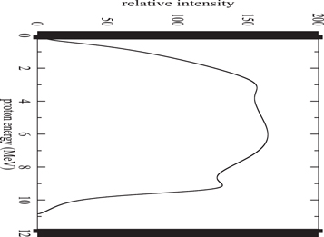
Figure 40. The predicted 3He + 3He proton spectrum for Ec.m. = 165 keV. Reprinted figure with permission from [13], copyright (2015) by the American Physical Society.
Download figure:
Standard image High-resolution imageIn the future, several issues could be clarified by improved experimental data. It would be very useful to extend the T + T neutron spectrum measurements to lower neutron energies to better constrain the fits and to possibly observe the double-humped structured predicted below 2 MeV neutron energy that is associated with the 5He ground state (see the 3/2− nα panel in figure 38).
A fully documented measurement of the α-particle spectrum from T + T would also be valuable, particularly if the spectrum could be measured up to the endpoint, where the di-neutron contribution is maximal. It would also be interesting to study the dependence of the spectrum on the energy in the entrance channel, as there is some indication the 5He ground state peak is more prominent at higher entrance channel energies [150]. On the theoretical side, it would be interesting and useful to extend our formalism to include the energy dependence in the initial state. We also expect that these methods can be applied to additional reactions or spectra with three-body final states, such as the 11B(p, 3α) reaction.
3.2.4. Energy loss
Experimental studies of charged-particle energy loss have a long history with accelerated ion beams and cold, neutral targets. A combination of Bethe's formula and empirical models are used to describe this experimental dataset [151]. More recently, accelerator-based measurements have been performed with plasma targets generated by discharge tubes and lasers ([152, 153] and references therein), which have covered electron densities of 1016–1020 cm−3 and temperatures (kBT) of 1–200 eV. Denser plasmas (1023 cm−3) have been investigated with 14.7 MeV protons produced by 3He(d, p)α reactions in ICF experiments [154, 155], either by passing the protons emitted from an implosion through a colder (32 eV), laser produced plasma [154] or by observing the energy downshift due to the hotter (0.5–4 keV), thermonuclear plasma [155]. Yet even denser plasmas (1024–1026 cm−3) have been studied with ICF experiments via neutrons from T(D, n)α reactions with energetic (E ≫ kBT) tritons or deuterons [54, 156]. Several energy loss models exist to treat the fully ionized hydrogen plasmas of ICF, e.g., see [156–160], but the measurements necessary to test their predictions are only now becoming accessible.
Stopping power investigations of the dense plasmas relevant to ICF experiments benefit from indirect approaches to measure energy loss, as the plasma dimensions often exceed the ranges of the charged particles emitted within the fuel. Neutrons avoid the range limitations as well as spectral distortions from remaining ablator and the strong electromagnetic fields that are due to laser–plasma interactions in the regions surrounding the compressed ICF capsule. Moreover, the neutrons serve as a relatively unperturbed diagnostic of the reacting particles' energies.
Indirect drive ICF experiments have used both gas-filled deuterium and cryogenically layered DT targets to study charged-particle stopping in plasmas, under conditions of weak to strong degeneracy (kBT/EF = 100–2) and coupling (Γ = 0.001–0.1). The weakly degenerate, weakly coupled plasmas of ICF hotspots can be studied with the gas-filled targets. Thermal D(D, p)T reactions within the hot core formed by imploding a deuterium-gas capsule create an isotropic and nearly monoenergetic source of 1 MeV tritons, and a small fraction (10−2) of these tritons initiate T(D, n)α reactions before either thermalizing or exiting the deuterium plasma. The secondary T(D, n)α neutron spectrum observed from an implosion reflects the velocities of interacting tritons in addition to the known neutron angular distribution and two-body kinematics of the reaction which transform these velocities into the spectrum. The stopping power acts on the velocities through their magnitudes, and affects the distribution of reaction energies, as the interaction probability changes with triton energy in proportion to the T(D, n)α cross section and inversely to the stopping power.
Radiation-hydrodynamic (HYDRA) simulations [150] are used to calculate the T (D, n)α neutron spectrum by simulating the time-dependent production and transport of tritons, from their origins in the hot core to their interaction points throughout the plasma. The standard prescription in HYDRA simulations treats charged-particle energy loss using Maynard and Deutsch's [156] version of the random-phase Born approximation for electron stopping and a binary collision description for ions [160]. Another model frequently used to calculate electron stopping power under these conditions, the Fokker–Planck formulation given by Li and Petrasso [157], was included for comparison.
Figure 41 presents the results of the neutron spectral analysis. By further reducing the energies of the tritons, the larger stopping power of Li and Petrasso's model increases the overlap between the energy distribution and the strong resonance in the cross section. The added reactions occur at lower triton energies, populating the neutron spectrum around 13–15 MeV, and makes the area normalized spectra for Li and Petrasso appear slightly narrower than Maynard and Deutsch in figures 41(c) and (d).
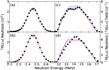
Figure 41. Extracted spectra (·) from D(D, n) 3He and T(D, n)α reactions are compared to simulations. Note that simulations are area normalized to measurements, and the normalization uncertainties of measurements are not included in the error bars. Data points are spaced in increments corresponding to the full width at half maximum of each detector's impulse response function, and contain statistical uncertainties from neutron interactions, photoelectrons, and digitizer noise (which can be smaller than the marker size). The D(D, n) 3He and T(D, n)α spectra are shown in the left and right columns, and the top and bottom rows correspond to detector along the (θ, φ) = (115°, 316°) and (161°, 56°), respectively. Results from the stopping models of Maynard and Deutsch [156] (red lines) and Li and Petrasso [157] (blue lines) are area normalized to the measurements, as described in the text, to emphasize differences in shapes.
Download figure:
Standard image High-resolution imageOrder-of-magnitude improvements in the neutron spectroscopy of secondary T(D, n)α reactions have been accomplished with the NIF. This advance now allows investigations of charged-particle energy loss using the neutron spectrum, and extends studies of stopping power to plasmas relevant to ICF, in which an understanding of α-particle heating is necessary to evaluate the performance of experiments and guide future designs. The general agreement found between the measured and simulated neutron spectra provides the first validation of several frequently used stopping power models for these plasmas.
3.2.5. Derivation of fuel areal density distributions from nuclear scattering signatures
The observed variations in FNAD activities, DSRs, and apparent yields measured along different LOS give information on the underlying capsule areal density distribution at bang-time. This distribution may be extracted from the data for each shot by fitting the nuclear measurements to a model comprised of a spherical shell whose size is determined by the NIS images and whose directionally dependent areal density is specified by the 9 coefficients of a spherical harmonic series summed to L = 2. The fit parameters are the 9 coefficients and the birth yield. The fitting function uses a Monte-Carlo to transport DT fusion neutrons from the hot-spot through the trial areal density distribution. Non-interacting primary neutrons and elastically scattered secondary neutrons are tracked to the detectors and counted; the results are used to predict values for the FNAD activities, the DSRs, and the apparent yield measurements. Nine additional Monte-Carlo runs, each with a single coefficient perturbed slightly from the trial value, are used to compute the derivatives of the predicted measurements with respect to each of the parameters. A modified Levenberg–Marquardt minimizer uses the predicted values and their derivatives to calculate a new set of areal density coefficients and birth yield attempting to minimize  (=sum of the squares of the differences between the predicted and measured FNAD activities, DSRs, and apparent yields over the squared errors). The new parameters are fed back to the Monte-Carlo for another step and the process is repeated until
  ceases to get smaller.
Figure 42 shows the results for N151007-001-999, an HDC layered shot whose FNAD activity distribution as well as the measured DSRs displayed a large north–south asymmetry. The best fit areal density, figure 42(a), indeed varies from 1.5 ± 0.1 gm cm−2 at the north pole to nearly zero in one spot on the equator. The other panels in figure 42 show the measured data (blue points) as a function of the cosine of the polar angle and the Monte-Carlo predictions (red points) using the best fit areal density. The fit had 35 measurements with 10 parameters and achieved a reduced  of 0.9.
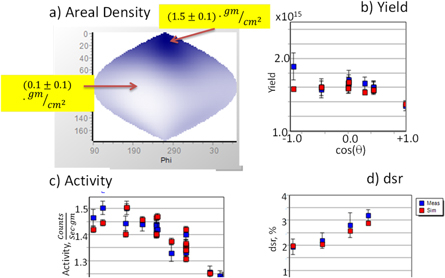
Figure 42. Areal density fit to the nuclear data of N151007-001-999; (a) best fit 9 parameter spherical harmonic areal density distribution; (b) measured (blue) and fit (red) yields as a function of polar angle from nToFs, MRS, and Zr and Cu NADs; (c) measured and fit FNAD specific activities; (d) measured and fit nToF and MRS dsrs. The fit values were calculated by Monte-Carlo using the areal density distribution in (a) after iterating to give the best fit to the data.
Download figure:
Standard image High-resolution imageIt is seen that this model fits the data very well showing that the measured activities, DSRs, and yields for this shot are consistent given the appropriate fuel areal density distribution.
This is true for most other layered DT shots which also obtain good fits using this method as seen from the  distribution of 26 shots shown in figure 43. The fact that the data fit this simple physical model tells us that the nuclear measurements are providing a consistent picture of the underlying areal density distribution. Current work is focused on how to use this method's best fit areal densities in more sophisticated HYDRA simulations.
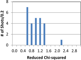
Figure 43. Reduced  distribution for 26 DT layered shots fit to the model described in the text. The model fits most shots giving us confidence in the consistency of the nuclear data.
Download figure:
Standard image High-resolution image3.2.6. GRH diagnostic for determination of ablator areal density in NIF implosion experiments
The CH shell ablator areal density in an ICF capsule can be diagnosed by measuring the γ-rays from inelastic neutron scattering of 12C [50, 161]. Experimental detection of the time-integrated γ-ray signal at 4.4 MeV using threshold detection from four gas Cerenkov cells provides a direct measurement of the 12C areal density near stagnation (see Herrmann article). Neutron spectrometers can in principle also probe the ablator areal density through measurements of neutrons that have lost energy through scattering in the CH ablator. However, for cryogenic DT shots, the down-scattered neutron signal is entirely dominated by down-scatter from the dense DT fuel layer. For surrogate implosions with the DT ice layer replaced with a thicker CH shell, comparisons can be made between GRH and neutron spectrum ablator areal density measurements, showing good general agreement between the two techniques [162].
GRH data collected from a recent high neutron yield campaign at the NIF reveals two general trends: less remaining ablator mass at stagnation and higher shell density with increasing laser drive. The findings are based on an analysis of experimental results from this recent high-yield campaign and the previous NIF Ignition Campaign (NIC), where Si-doped hydrocarbon ablators were used [163]. The laser drive was modified from the four pulses in the NIC to three with a higher energy first pulse ('high foot') in the high yield campaign. Physical estimates and radiation hydrodynamic simulations suggested that this choice of laser drive would suppress fuel ablator material mixing by reducing the compressibility of the DT fuel. The loss of compressibility with the 'high foot' pulse decreases the likelihood of ignition, but increases the overall stability of the implosion [164]. An increase in neutron yield by a factor of ten and very little ablator mix for the 'high foot' implosions was obtained compared with the best performing implosions during the NIC. For the 'high foot' pulse, the fuel areal density declined by 30%. In addition to the laser drive alteration, three different initial ablator outer radii were investigated: a thicker shell matching that used in the NIC with 195 μm, and thinner shells with 175 and 165 μm radii. The variation in hydrocarbon shell thickness was selected to systematically increase the maximum implosion velocity without further increase in the laser drive power. Since these implosions produced higher neutron yield, there is interest in quantifying the implosion characteristics in detail.
A validated three-dimensional static model used in earlier NIF campaigns was applied to the interpretation of the experimental data [117]. This model correlates the NIF implosion diagnostic information to deduce the thermodynamic properties of the burning core, the spatial density distribution of the DT fuel and the remaining hydrocarbon ablator to generate a self-consistent description of the time-averaged implosion conditions. A three-dimensional volume is derived from neutron images; assuming isobaric conditions at implosion stagnation, the hot core density and temperature variation are obtained; and the directional nuclear scattering and activation data is used to reconstruct the shell and ablator density distribution. The original DT fuel mass is conserved but the remaining hydrocarbon mass is variable.
Of special interest in the work described here is the use of the time-integrated 4.4 MeV 12C γ emission to fit the hydrocarbon areal density in the context of this model and thereby derive a better qualitative understanding of the stagnation conditions. Constraints for the ablator areal density arise from estimates of the remaining hydrocarbon ablator mass [165, 166] and the ablator mass mixed into the burning core [167]. In the case of the high-yield series of implosions [164], very little ablator mix was observed in the burning core, implying that the remaining ablator material is either located in a compressed shell around the DT fuel assembly or entrained in the fuel assembly, or both. The ablator mass at stagnation is typically estimated from so-called convergent ablator implosions, which rely upon x-ray back-lighting to measure capsule velocity and remaining mass. These companion implosions used the same laser drive conditions but replaced the DT ice layer with a comparable mass of ablator hydrocarbon. The selected cryogenic implosions varied the laser energy, power, hohlraum lining material and ablator thickness to increase the incoming shell velocity, which induced significant differences in the remaining mass and the GRH-derived ablator areal density.
Data fits described in [50] using the three-dimensional model to six of the high-yield implosions were performed for two of the thicker, two thinner and thinnest capsule configurations and one of the better performing NIC implosion experiments was included for comparison. The original static model was modified to replace the previous constant hydrocarbon ablator region with a quadratic exponentially decaying functional form [50]. As an example, density profiles in a fit are plotted in figure 44. An exponential form is physically reasonable since the hydrocarbon layer is releasing material without a boundary constraint after the shock passage that creates stagnation conditions while the quadratic decrease accounts for the spherical geometric contribution. Furthermore, the use of this simple fitting form provides some initial qualitative insight into the differences among the chosen implosions. The analysis assumes an implosion assembly consisting of the DT gas and DT fuel layer, with the remaining hydrocarbon ablator conformal with the exterior of the DT fuel layer. The DT regions are assumed to be uncontaminated by ablator material and the exterior ablator region is described by a linear exponential form decreasing quadratically beyond a radius r0 and matched to a Gaussian form that describes the DT fuel density

where r0 is the matching radius and α is the inverse decay length. The ablator density at r0 is required to match the compressed fuel Gaussian form which has a peak density of r0, with a full width at half-maximum b, and radius at peak density of ra. The Gaussian form is independently determined by fitting the x-ray and nuclear diagnostics, so the three parameters r0; b and ra, are known. The remaining two parameters, α and r0, are determined using the GRH measured hydrocarbon areal density, ρCH, and the estimate of the remaining ablator mass, mCH. The standard 'Heaviside' step function, Θ(s), is zero for s < 0 and one for s ≥ 0. The angle-averaged areal density constraint yields ρCH = 1/4π ∫dφ∫dθ sinθ ∫dr ρ(r) = ρDT (r0) r0(1 + αr0Ei(−αr0)) where Ei (x) is the exponential integral function. Application of the remaining mass constraint produces a simple relationship between the matching radius and inverse decay length

since mCH is known experimentally. Replacing α in above produces a nonlinear equation for the remaining fit parameter, r0. This nonlinear equation is readily solved by standard numerical techniques and a comparison of the selected implosion experiments is presented in [50], where the DT fuel layer parameters are assumed to be ra = 50 μm, b = 106 cm−2, and ρ0 = 500 g cm−3.

Figure 44. Representative radial lineouts of the density distribution in the shot N140511 using the decreasing quadratic and exponential decay functional fit to the remaining hydrocarbon ablator. The black, red and green curves refer to angles of 0, π/2 and π radians respectively. Reprinted with permission from [50], copyright (2016), AIP Publishing LLC.
Download figure:
Standard image High-resolution imageWithin the context of this over-simplified approach, conspicuous trends may be distinguished as a function of increasing implosion drive. For example, the lower x-ray drive implosions, and lower laser energy drive implosions, have qualitatively similar matching densities and radii, whereas the higher drive implosion shots display much higher matching densities and significantly reduced matching radii. The increased laser drive of these later shots, due to a combination of higher laser energy and the additional uranium hohlraum liner, compressed a smaller amount of ablator mass to an approximate three-fold increase in density at a 10% reduced radius.
There is a clear violation of this trend for the thinnest shell implosion. Since the remaining ablator mass is relatively large but with a small GRH-inferred areal density, the matching density is quite low at the large matching radius and the range, α−1, is large. These values suggest a significantly extended fuel and ablator assembly at stagnation.
In three-dimensional fits to the selected implosions, more realistic conditions are introduced into the model. The density and radius at which the exponential model for the remaining ablator material begins is now a function of radial distance and spherical angle; hydrocarbon material may be introduced into the DT gas and fuel assembly; and other experimental constraints such as the burning core volume and fuel areal density are imposed. Figures 45(a) and (b) [50] show results of the extended fitting procedure by comparing identical cross sectional views of the stagnated assembly in the equatorial plane for the analyzed implosion experiments. The better-performing low-adiabat implosion achieves the most favorable combination of high density mass distribution and relatively uniform assembly symmetry. The subsequent high-adiabat implosions do not attain this uniformly high density distribution. Second, all of the high-adiabat implosions appear to have cold fuel shape distortions and, in some cases, burning core asymmetries. Third, there are two implosions in which the peak hydro carbon ablator layer density is several times larger than the peak densities in the other high-foot implosions. An examination of either the spherical or three-dimensional matching densities or the associated ranges for these shots reveals substantially higher matching densities and much shorter ranges. According to this analysis, the ablator was thus conformally compressed with the DT fuel layer. In all the considered cases, though, the hydrocarbon ablator layer clearly remains outside the regions of highest DT fuel density corroborating the expected behavior of the high-adiabat design in this shot series.
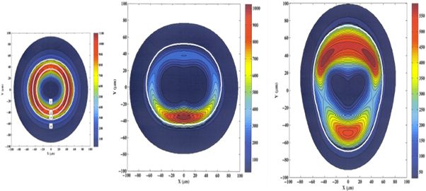
Figure 45. (a) The various fitting regions (1)–(4) demarcate volumes of DT gas (1), the inner solid DT fuel layer (2), the outer DT fuel layer (3), and the hydrocarbon layer (4). Regions 1–3 can have variable hydrocarbon mix depending upon the specific details of an individual implosion. (b) Equatorial view of the density distribution obtained in the fit thinnest shell. The highlighted white contour marks the matching radius at which the hydrocarbon layer begins. Reprinted with permission from [50], copyright (2016), AIP Publishing LLC.
Download figure:
Standard image High-resolution imageA straightforward comparison to the spherical results may be obtained by a simple average of the angular matching densities and radii [50]. Despite the large angular asymmetries in the shell density distributions obtained for many of the implosions, the spherical model captures the qualitative behavior of the compressed hydrocarbon ablator layer. For example, the matching radii are quite similar, except for uneven mass distributions. The trend of increasing matching density with increasing implosion velocity is reproduced in two high-foot series cases but fails for another later thin shell case.
Perhaps indicating the onset of shell disruption, the stagnation characteristics of the very thinnest shell implosion are quite degraded compared to the other high-adiabat implosions but this difference likewise appears in both the spherical and full three-dimensional models. The GRH results are thus in qualitative agreement with the expected experimental implosion design and provide a quantitative measure of the relative difference in stagnation performance. Within the context of these simplified fitting techniques, the GRH-inferred ablator areal densities usefully complement the other stagnation diagnostic signatures and permit an extension of the three-dimensional static model to describe the time-averaged hydrocarbon density distribution at stagnation. In contrast, very little ablator mix into the burning core is detected as measured by the standard x-ray yield diagnostic.
The analysis suggests that further valuable information about ignition-relevant implosions resides in the 4.4 MeV gamma-ray signal. Some of the most important outstanding issues in the approach to achieving ignition concern the amount of DT fuel-ablator mix occurring and the overall compressibility of the assembled DT fuel and remaining ablator. As noted above, these issues might be directly diagnosed using the time-integrated 4.4 MeV gamma-ray emission as captured by the GRH diagnostic.
Finally, we note, the 4.4 MeV GRH data complement the existing solid radiochemical collection (SRC) diagnostic fielded at the NIF. The SRC data measures the ablator hydrogen whereas the 4.4 MeV signal arises from the ablator 12C [161].
3.2.7. Solid debris analysis for nuclear reaction studies utilizing catcher foils
The study of nuclear reactions at the NIF, requires the collection and analysis of the reaction products, as well as the target matrix (e.g. target material inside a capsule or attached to the hohlraum) during ICF experiments. For solid materials, this is accomplished through the use of catcher foils (solid debris collectors) placed within the TC, as described in section 2.1.9 radiochemical diagnostics (RC). These collectors (typically vanadium, tantalum or graphite) intercept the exploding NIF target assembly during a shot. The target mass, now both atoms and particulates, is collected, removed from the chamber and analyzed using various techniques: photography, microscopy, spectroscopy and spectrometry.
The surfaces of these collectors, orthogonal to the TCC, are exposed to extremely harsh radiation and thermal environments during ICF experiments at NIF. As a result, the exposed area of the collector undergoes significant changes due to melting, impact and ablation processes from the irradiation, along with the dispersal of the target assembly mass [112]. Initial examination of the collector surfaces are typically performed with two nondestructive techniques: optical microscopy and scanning electron microscopy coupled to energy dispersive x-ray spectroscopy (SEM–EDX).
Optical photo-microscopy provides visual information regarding the macroscopic features of the debris distribution and collector surface deformation. For example, shrapnel debris is more commonly observed on the surface of collectors in the polar direction of the NIF chamber. Graphite collectors fielded on this line-of-sight show the cratering impacts and penetration of macroscopic ballistic debris, figure 46(A).
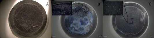
Figure 46. Micrographs of solid debris collectors fielded at 50 cm from the target assembly. The graphite collector was fielded on the polar DIM (A), the tantalum collectors, (B) and (C), on the equatorial DIMs, 90–315 and 90–78, respectively. The larger micrographs were captured with 5× magnification, while the inset micrographs were taken at 40×.
Download figure:
Standard image High-resolution imageFor metallic debris collectors, surface features such as melting and movement of surface mass are clearly visible in similar photomicrographs, figure 46(B). Further, splats of melted solid debris, observed even at 5× magnification, are more clearly displayed in the 40× micrograph, figure 46(C).
The superior magnification and imaging of the SEM/EDX coupled spectroscopy system allows more detailed examination of solid debris and the collector surface. The SEM, which produces an image of the surface through raster scanning with a focused beam of electrons, provides detailed surface topography and composition. Magnification of up to 10 000× can be utilized by this technique. The target debris field at NIF is heterogeneous, as evidenced by the diverse debris collected on a single collector, figures 47(A)–(D), which had a collection area of 12.6 cm2 at 50 cm from TCC (solid angle of only 4 × 10⁻⁴). Furthermore, extremely valuable information can be extracted from these spectroscopy images, such as evidence of geometric fractionation by two distinct splats of solid debris, figure 47(C). The EDX capability provides an analytical method for qualitatively assessing the composition of collected debris by measuring the emission of characteristic x-rays from regions of interest, figure 47(D). This nondestructive method allows the assessment of the distribution of solid debris, collector surface properties, structural features of the debris and qualitative element identification of the debris composition. The quantitative analysis of solid debris via nondestructive gamma spectrometry is performed routinely for the SRC nuclear diagnostic [113] and has also been utilized in a fractionation study of NIF target debris [168]. The major advantages of this method are that it allows high-resolution, direct counting of the debris collectors with high-purity germanium detectors after minimal sample preparation time. Thus, for an experiment where short-lived radionuclides are of interest to study a nuclear reaction at NIF, this method of prompt, nondestructive analysis is preferred. However, it also has certain disadvantages that make it unsuitable for analysis of many reaction products, as well as all stable/long-lived materials.
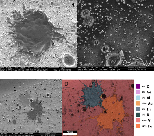
Figure 47. SEM images of diverse solid debris collected on the same vanadium collector in experiment N130710: splat of melted debris at 9200× magnification (A), low-Z crystalline material at 5900× (B) and splats of two distinct materials at 670× (C). The EDX map scan (D) of the previous image (C) for identification of the material matrix.
Download figure:
Standard image High-resolution imageThe reaction products produced at trace levels may be difficult or impossible to quantify with reasonable uncertainties through direct counting of the debris collectors due to: interferences from other reaction products with similar or higher-energy photon energies, and/or more commonly, low production rates for the reaction products of interest. Consequently, radiochemically pure samples will be necessary to increase the sensitivity of nuclear counting measurements by removing unwanted reactions products (including activation products in the collector material). Therefore, destructive methods have been developed for the recovery of solid debris from collectors, entailing subsequent radiochemical separation methods followed by analyses via nuclear counting and/or mass spectrometry.
The surface of the solid debris collectors can be leached using different combinations of mineral acids/bases. Provided that the solid debris is collected within the first few surface μm of the collector [112], the process typically recovers 95+% of the debris. The collection efficiency of the leaching process can be measured through a radioactive component of the collected debris. The leached solution can then be traced with other radionuclides of interest for further processing of the sample. These processes typically require development of new separation methods tailored toward a specific experiment/analyte of interest. For example, a procedure was developed for the recovery of lanthanides from vanadium collectors to address the debris distribution over the VADER collection system [169]. This new method required the separation of microgram amounts of lanthanides from grams of vanadium collector matrix [170]. Similarly, other radiochemical procedures have been developed to address experimental needs, such as the recovery of gold hohlraum debris from graphite collectors [171]. The final radiochemical pure fraction, containing the reaction products and/or stable elements of interest, produces a higher fidelity measurement by addressing the two major disadvantages of nondestructive gamma spectrometry given above. The subsequent instrumental techniques of gamma spectrometry and mass spectrometry (although not limited to these) can produce measurements with detection limits on the order of 105 atoms and 0.1 ppb or better, respectively (assuming normal background levels).
3.2.8. Ablator/fuel mix diagnostic for layered DT ICF shots from radiochemical analysis of Au isotope ratios
Based on the measurements of 198Au/196Au activation ratios collected from activated Au hohlraum material, a new method to determine fuel (DT) and hydrocarbon ablator (CH) areal densities has been developed. The Au ratio combined with the independently measured (nTOF) DSR uniquely determines the areal density of DT and CH in the context of a semi-static 1D capsule model.
The areal density, ρR, of the compressed fuel around the hot spot is typically inferred from the neutron down-scattered ratio DSR = Φ(10–12/13–15) [172]. However when ablator contributions become appreciable, attributable to more remaining ablator mass or entrainment of ablator material into the DT fuel layer, a more accurate method that uses both the DSR and the activated Au ratio for analysis is required. The DSR and Au ratio have different dependencies on ρR(DT) and ρR(CH) due to different cross sections and kinematics (DSR = 0.045ρR(DT) + 0.012ρR(CH)) and (Au ratio = 0.000 74 + 0.0015ρR(DT) + 0.0010ρR(CH) + O((ρR)2) where the ρR values are in g cm−2. The Au ratio is more sensitive to low energy neutrons since the 197Au(n, γ) cross section rapidly increases with decreasing energy. The nonlinear behavior of the Au ratio for large ρR values is due to multiple neutron scattering (trapping) in the capsule before the capsule disassembles. The proposed one-dimensional analysis uses the DSR and Au ratio values as constraints, along with several hot spot and cold fuel parameters, to iteratively to fit the unknown fuel and ablator ρR.
Approximately a dozen 'low-foot' ignition shots performed during the NIC in 2011–2013 [173] have been analyzed that show consistently large ρR(CH) values ∼0.7 g cm−2. A plausible explanation is mixing of the ablator at the interface with the cold fuel. A precise determination of the mix fraction is not possible with this model since the density profiles of fuel and ablator are unknown, as opposed to their measured areal densities.
The radiochemical method for estimating ρR(CH) is complementary to observing neutron induced 4.44 MeV gammas from 12C excitation [174]. The radiochemical signature is most sensitive to hydrogen scattering in the ablator whereas the 12C gamma ray signal is obviously produced by 12C-neutron scattering. Although the methods are complementary, the radiochemical analysis is more flexible since it could be used in cases with alternative ablators, e.g. Be, where no useful gammas are produced [175].
3.2.9. Neutron capture cross section measurement for 14 MeV neutrons on 197Au in a DT exploding pusher shot
The neutron capture cross section 197Au(n, γ)198Au at 14 MeV has been measured on the NIF with high accuracy (10%) and negligible room return by utilizing an exploding pusher platform [176]. This cross section is not well known with only a few separate measurements published [177–181]. The values separate into two clusters of data as shown in figure 48. The evaluated cross section (ENDF/B-VII.1) follows a weighted average of the data in that energy region.

Figure 48. ENDF/B-VII.1 evaluated and measured 197Au(n, γ) cross sections near E = 14 MeV. The 'NIF' data point is based on activation data from the exploding pusher shot N130503.
Download figure:
Standard image High-resolution imageAn exploding pusher DT gas-filled target with low convergence was used (N130503) to provide a nearly monoenergetic 14 MeV neutron source with small contributions from DD and TT reactions; the measured ρR ∼ 52 mg cm−2 was small at burn time minimizing neutron down scattering. The time-integrated escaped neutron spectrum was calculated using HYDRA. The static MCNP code with ENDF/B-VII cross sections and the detailed hohlraum geometry gave the expected Au activation ratio. The (n, γ) and (n, 2n) reactions in the Au components were computed by tallying the energy dependent neutron fluence weighted by the Au cross sections. The room-return contribution to the (n, γ) signal was negligible due to the proximity of the Au to the neutron source. The cumulative (n, γ) spectrum shows that 65% of the 14 MeV neutrons account for the capture with smaller but significant contributions from DD, TT and down scattered (Al, Au HR material) neutrons. The ratio of calculated (n, γ) to (n, 2n) reactions integrated over all Au material in the hohlraum yielded an Au ratio of = (1.11 ± 0.05) × 10−3, where the estimated error is due to the uncertain spatial origin of the collected Au debris. The measured Au ratio [182] was (9.1 ± 0.6) × 10−4 and was significantly smaller than the calculated value.
A reasonable procedure for bringing them into agreement is by adjusting the controversial 197Au (n, γ) value at En = 14 MeV, while keeping the ENDF/B-VII.1 cross section values at lower energies. The resulting cross section value σ(n, γ) (En = 14 MeV) = (0.95 ± 0.13) × 10−3 b (roughly 30% lower than in ENDF/B-VII.1) was used in a modified ENDF/B-VII.1 file for the analysis of layered DT ignition shots [183]. To our knowledge this is the first time an ICF neutron source was used for a neutron cross section measurement.
3.2.10. Gaseous debris analysis for nuclear reactions utilizing RAGS
Nuclear reaction detectors are chemical elements or enriched isotopes that undergo nuclear reactions and may be placed in several locations to provide diagnostic information or basic science data. Isotopes of the noble gases or the halogens (bromine or iodine) are quite versatile as detectors for neutron or charged-particle reactions and the gaseous products are collected with high efficiency in the RAGS system [6] (see 2.1.9).
A significant advantage of gas collection is the high collection efficiency, approximately 95% of the shot-produced gases from the NIF TC is collected in a 15 min sampling period. A second advantage is the ability to provide high precision values for the absolute number of product atoms by combining decay counting on calibrated detectors with isotope dilution mass spectrometry of stable isotope tracers released on each shot. A third is the lack of background contributions for radioactive noble gas species, which simplifies data analysis. To date, we have seen only 133Xe (t½ = 5.24 days) generated from the fission product 133I (t½ = 20.8 h) remaining in the TC after a DT shot containing depleted uranium (DU) in the hohlraum or target capsule. If RAGS collects a sample within 3–4 weeks of a shot that created fission products, a 133Xe background component will be present.
3.2.10.1. Detectors loaded into DT Fuel
In 2012, the RAGS commissioning test used an exploding pusher capsule with DT fuel loaded with 0.28 atom percent of an isotopically-enriched xenon gas mixture (124Xe, 126Xe, 128Xe with atom fractions of 0.52:0.44:0.04). The shot released radioxenon products of (n, 2n) and (n, γ) reactions (123Xe, 125Xe and 127Xe) into the TC, which were collected in RAGS and counted with an in situ LaBr3 detector, demonstrating the capability to collect and measure gaseous radioisotopes produced in a NIF shot. The gas was transferred to another lab for preparation of a counting aliquot that was analyzed on an HPGe detector in the low background NCF. We determined the relative (n, 2n) cross section ratios at 14.1 MeV by decay-correcting each nuclide to shot time and normalizing to the ingoing isotopic composition with the assumption that neutron capture contributions were small compared to the (n, 2n) products [6]. Subsequent addition to the NIF TC of an automated stable-isotope tracer injector loaded with a known amount of 129Xe allowed determination of the absolute number of tracer atoms recovered on each shot. If the tracer mixes completely with the nuclear reaction products in the TC, the same collection efficiency can be applied to the radioactive species of the same chemical element. The tracer reservoir can be exchanged so that different tracer mixes can be used; for example, in 2015 a mixture of 82Kr and 129Xe was installed. In 2014, a translatable HPGe detector replaced the LaBr3 on the collector cart in order to provide better energy resolution for peak identification and allow quantification of short-lived species after detector calibration [184]. The current capabilities permit relative neutron cross section measurements for detectors that can be loaded into the fuel and collected in RAGS; and absolute measurements for detectors that can be traced with a gaseous compound.
3.2.10.2. Detectors intrinsic to or loaded into the capsule ablator
Ablator-fuel mix or areal density measurements of the ablator may be probed by short-range, charged-particle reactions or by neutron-induced fission on uranium implanted in the ablator. RAGS's large collection fraction for gaseous products makes many of these measurements feasible. With plastic or HDC capsules, charged-particle reactions, primarily (d, n), on the intrinsic carbon nuclei within approximately 6 µm of the fuel/ablator interface, produce 13N (t1/2 = 9.97 min, positron emission), which is seen at 511 keV by the LaBr3 detectors on the first and second hot RAGS getters on the Filter cart. Mix estimates from model calculations require the absolute number of 13N produced. However, calibration of these getters to obtain this value is extremely difficult because of the complicated geometry of the getter and the temporal change in its chemical reactivity, which affects the amount of nitrogen fixed on the getter. Instead, it will be simpler to bypass the getters and capture 13N in the abort tank by modifying some RAGS hardware and the collection procedure. Calibrating the abort tank should also be easier due to its cylindrical geometry and the ability to use the (n, 2n) reaction on 14N to produce 13N during a NIF shot. Pieces of boron nitride (BN) glued to the outside of the target assembly should provide sufficient signal for calibration, with the caveat that the BN converts nitrogen to gaseous species that pass to the abort tank. Alternatively, longer half-life 18F (t1/2 = 2.09 h, positron emission) from irradiation of a fluorine-containing material could be used for the abort tank calibration.
Other charged particle mix detectors (i.e., bromine or iodine) could be added to the first 6 µm of the ablator behind the fuel interface where (d, 2n) reactions produce 79Kr or 127Xe. If specific sections of the capsule could be loaded with unique detectors, then mix from each section could be determined and compared to the overall mix measured by 13N to investigate whether differential mix occurs. An initial set of bromine-doped capsules was fabricated in 2014, but improvements in the capsule processing are needed before a suitable target can be fielded.
Neutron reactions may also be used to characterize ablator mix. Two xenon isotopes were successfully implanted at unique radii in a plastic capsule to test the change in activation due to mix. 124Xe was placed at 45 µm from the inner surface and 136Xe at 132 µm in the symmetry capsules. The capsule growth and ion implantation of the stable xenon isotopes, required several iterations. Mass spectrometer measurements on out-of-spec finished capsules showed that the implanted gases, each at the level of about 2 × 10¹⁴ atoms, were retained throughout capsule fabrication. Early in the process, it was found that the mandrel had to be removed prior to the implantations to prevent loss of implanted xenon. The full-sized, nominal thickness capsules are currently available for shot scheduling.
RAGS participated on two shots where DU was doped into the ablator. Gaseous fission products were collected to determine the number of fissions that occurred during each shot. When normalized by the 14 MeV neutron yield and the abundance of DU dopant, these measurements provide an estimate of the areal density of the dopant layer within the ablator at bang time. Ablator areal density estimates provide constraints on laser drive efficiency, hydrodynamic simulations, and potentially the presence of hydrodynamic instabilities (mix). Fission product measurements from DU dopant, like measurements of (n, 2n) and (n, γ) reaction products generated from Xe dopant layers (discussed above), could thus provide highly localized estimates of ablator areal density.
3.2.10.3. Detectors located external to the target assembly
Detectors placed external to the target assembly provide opportunities to measure cross sections, perform basic science experiments and characterize neutron scattering at mounting locations. DU in the hohlraum generates fission products from high energy neutron interactions. RAGS collected the gaseous products and independent fission yields for several xenon radio-isotopes have been determined (see Cassata et al below) [185]. Foils implanted with noble gases, or small rectangular pieces of rigid materials, called postage stamps, may be glued to the outside of the target holder at a fixed and well-known distance with respect to the target center. Neutron reactions on intrinsic or implanted components of these materials generate radioactive species which are released in gaseous or solid debris and collected by RAGS or solid debris catchers (SRC). Gases contained in a re-usable aluminum cell mounted on a DIM may be irradiated and then recovered intact for measurement at the NCF or split for detector calibration. The cell face is located at a radius of 46.5 cm from the NIF TCC. A cell can hold up to 42 cc STP gas, and each DIM can hold four cells. The cells were commissioned in late 2015 using three different xenon isotope mixes: atmospheric xenon; pure 134Xe; and a 4:1 mix of 124Xe:136Xe. Figure 49 shows a gamma spectrum from the third mix.
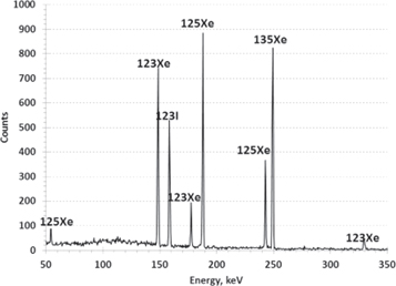
Figure 49. Nuclear Counting Facility HPGe gamma ray spectrum of products from (n, 2n) and (n, γ) reactions in a 124Xe:136Xe mixture that was loaded into a gas cell and irradiated on NIF shot N151105-001-999. The decay daughter, 123I, accumulates in the counting cell.
Download figure:
Standard image High-resolution image3.2.11. Short pulsed, high flux neutron induced fission in 238U
The RAGS system (see 2.1.9 [6]) is a diagnostic apparatus designed to collect, purify, and analyze gaseous reaction products. The system is very efficient at processing TC gases (>95% pumped through RAGS) and is equipped with on-site counting capabilities that enable measurements of nuclides with short half-lives (as short as 10 s). On shots wherein the target hohlraum is lined with DU, D–T fusion neutrons undergo fission reactions with the hohlraum producing xenon (Xe) and krypton (Kr) isotopes and their precursors (Sn, Sb, Te, I, Ge, As, Se, and Br), which subsequently undergo decay to isotope of Xe and Kr in the TC. Here we provide an overview of the gas collection, purification, and measurement procedure used to determine fission yields of Xe and Kr isotopes produced in the NIF TC.
The RAGS diagnostic is equipped with several scintillation detectors for measuring gamma ray emissions from gases trapped at different stages of the system (see 2.1.9). There are two lanthanum bromide detectors on the filter cart, one of which is located adjacent to the exhaust pipe from the water vapor trap, and one of which faces the stainless steel housing surrounding the first hot getter. There are also two high purity germanium (HPGe) detectors, one of which is located above the cryogenically cooled Cu collection foam where Xe is typically trapped, and one of which is flush against the upper wall of the shielded abort tank. The HPGe detector located above the collection foam is affixed to a translatable stage, such that its position can be optimized to reduce detector deadtime. All fission product yield measurements are conducted using the HPGe detectors above the abort tank and collection foam, with data acquisition performed in list mode (i.e., each registered event has an associated timestamp). In [6] a detailed description of the individual hardware components and their operation is given.
Figure 50 illustrates typical gamma ray spectra obtained using the HPGe detectors located above the collection foam and abort tank. Photo-peaks observed in the collection foam HPGe detector spectrum are associated with isotopes of Xe and its daughter products Cs and Ba, with the exception of the 511 keV photo-peak from 18F decay (t1/2 = 109.77 min) and photo-peaks from Kr decays 'in flight' as it is pumped to the abort tank. Photo-peaks observed in the abort tank HPGe detector spectrum are associated with isotopes of Kr and its daughters Rb and Sr, except for the 440 keV photo-peak from 23Ne decay (t1/2 = 37.2 s).
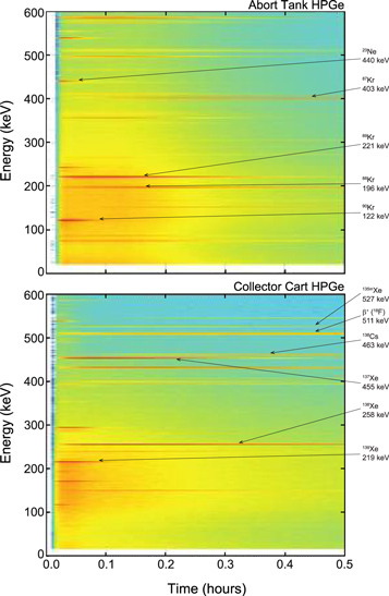
Figure 50. Gamma ray spectra obtained from the HPGe detectors located above the (a) abort tank and (b) Cu collection foam (Shot N150115). To improve the clarity of the figure, only gamma rays with energies of 0–600 keV are shown, from 0 to 0.5 h after shot time. Select high intensity photo-peaks are identified for reference.
Download figure:
Standard image High-resolution imageFor each nuclide identified, background subtracted time-resolved photo-peak intensities are calculated from the list mode data. Nuclides first appear at the collector cart approximately 20 s after shot time. Decay-corrected photo-peak intensities increase throughout the 15 min collection interval as the fission products are pumped from the TC to the RAGS system in the basement of NIF, and due to ingrowth of Xe and Kr from precursor nuclides that decay in the TC [185]. Because of this dynamic pumping process, the decay-corrected activity ratio of any two nuclides initially reflects the ratio of their independent yields, and generally subsequently approaches the ratio of their cumulative yields. In [185] a detailed description of extracting independent and cumulative fission yields from gas collections at the NIF is provided.
The nearly instantaneous, high-flux neutron source provided by the NIF, coupled with the rapid, on-site gas collection and counting capabilities, enables quantification of nuclides with half-lives as short as 10's of seconds. Thus far, 140Xe, 139Xe, 138Xe, 137Xe, 135Xe, 135mXe, 133Xe, 133mXe, 91Kr, 90Kr, 89Kr, 88Kr, 87Kr, and 85Kr have been measured. A summary of Xe fission yield determinations is given in [185], and calculations of Kr fission yields are in progress. The experiments conducted to date demonstrate the feasibility of fission product measurements at NIF, and efforts are underway to improve the operational protocol of the RAGS system. Future work using the RAGS system will focus on measurements of charged particle reaction products as implosion performance diagnostics.
4. Future facility development and proposed nuclear research
4.1. Compton radiography using NIF-ARC
ICF implosions can be severely degraded by asymmetries in the laser-induced x-ray drive and by hydrodynamic instabilities due to capsule imperfections. These asymmetries can be measured by time-resolved x-ray radiography of the dense cold fuel surrounding the hot spot.
Radiographs can be obtained using Compton scattering rather than traditional photo-absorption to cast a shadow of the imploding capsule [186]. Indeed, the optical depth of the fuel of an ICF target is dominated by the Compton cross section for photon energies above ∼30 keV and is largely independent of photon energy, between 40 and 200 keV. Therefore, the areal density of the fuel can be directly measured using a broadband (i.e. bremsstrahlung) emitting source with the energies of the x-ray photons producing the radiograph selected by a combination of a high-pass filter and the response function of a gated hard x-ray detector used to optimize signal to background.
Hard x-ray radiography allows filtering of the self-emission from the stagnating capsule, which is concentrated largely below ∼20 keV, thus producing radiographic images near peak compression. Moreover, since Compton scattering is sensitive to electron density, and not to the atomic number, as in the case of the photoelectric effect, it is ideal for probing the low-Z DT fuel in ICF implosions, thus avoiding opacity effects that depend upon the temperature and density of the material. Short-wavelength photons will also minimize the refraction of the probing x-ray beam as it traverses the shell and thus will keep the spatial resolution close to the backlighting source size.
Since Compton radiography can produce high resolution images of the fuel near bang time, it provides experimental data that complement nuclear measurements. Of particular interest will be the study of the correlations between Compton radiographs and images produced by the NIS, as well as the comparison of the areal density asymmetries derived from the radiographs with the measurements of DSR.
On the NIF, we plan to generate the stagnation phase radiographs using 5–25 μm-diameter Au wires in an end-on, point-projection geometry, irradiated with the short pulses from the NIF advanced radiographic capability (ARC) [187]. Currently ARC provides four beams which can be pointed independently and at different times to generate time-separated backlighting sources and therefore time-spaced snapshots of the cold fuel around the time of peak compression. These radiographs will be used to perform two-dimensional reconstructions of the fuel density and shape. The main concerns for successfully recording Compton radiographs of the fuel are related to the extreme background levels expected during the implosion. Consequently, a newly developed detector, the ARC x-ray Imaging System (AXIS), will be deployed on DIM (90, 78) [188]. The AXIS detector uses a chevron stacked MCP configuration to increase the quantum efficiency of the hard x-ray signal. Backgrounds are mitigated by the gated MCPs and by a combination of collimators arranged on both the hohlraum and the AXIS snout.
The accuracy of the fuel areal density measurements depends mainly on the signal-to-noise ratio (SNR) and on the contrast of the recorded radiograph. For the estimated background levels on NIF and the design described above, we expect 5%–10% accuracies for the measurements of limb-averaged ρR for implosions having ρR ∼ 1 g cm−2. If we limit ourselves to SNR and contrast, the accuracy in areal density measurement is given by  therefore an increase in areal density will allow better accuracy and vice versa.
As an example of the expected radiographs, figure 51 shows a simulated 10 μm/30 ps, spatial/temporal resolution, Compton radiograph of a THD implosion, with and without the expected noise background. Statistical analysis (50 realizations of the radiograph) along the limb contour shows peak fuel density an/a0 shape accuracy of 3% for n = 2 and 4, where an is the amplitude on the nth Legendre mode.

Figure 51. Simulated 10 μm/80 ps, spatial/temporal resolution. Compton radiograph of a THD implosion. Without noise (a) and with noise expected when using ARC beams to generate the back lighter.
Download figure:
Standard image High-resolution imageThe AXIS detector is equipped with a snout that hosts an array of pinholes to image the emission from the hot core onto an Imaging Plate [189]. Even though these images are time integrated, because the detector is not gated, they will be in line with the Compton radiographs and will allow to spatially register the position of the fuel radiographs with respect to the core and therefore have a direct comparison between the core and the fuel images. Moreover, once the position of the fuel radiograph has been related to the position of the core, it will be possible to correlate the fuel radiographs with the time-resolved, high resolution core images recorded by the time-resolved x-ray imagers, such as the dilation x-ray imager [190] or with the down-scattered neutron images.
4.2. Diagnostic systems
4.2.1. Extended flight-path (100 and 120 m) nTOFs
The current nToF spectrometer system is optimized for making precise, accurate measurements for neutron kinetic energies 2 MeV ≤ En ≤ 15 MeV. Neutrons with energy below and above this region offer the possibility of additional diagnostics for NIF implosions as well as opportunities for measuring nuclear cross sections.
A pair of low (<2 MeV) and high (>15 MeV) neutron energy detectors located at roughly 100 m from TCC would greatly enhance the quality of the neutron spectroscopic data currently obtained in NIF implosions (figure 54). The pair would consist of complementary detectors: a LENS to measure neutrons from 10 eV up to 100 keV, and a high energy NTOF (HENTOF) detector to measure up to 32 MeV. LENS extends the lower range of NTOF spectroscopy down to ∼eV scale. With such a spectroscopic tool, cold fuel temperature, confinement time, and low energy cross sections are measurable. The HENTOF detector will improve the resolution and precision of traditional neutron spectroscopy measurements (DD, TT, and DT Tion, DSR, yield), while providing additional high energy information. The HENTOF can improve measurements of the reactions in flight (RIF) neutron spectrum at much higher energy resolution than possible with existing NTOF spectrometers fielded at the NIF
Neutrons in the energy region 10 eV ≤ En ≤ 100 keV are sensitive to the cold fuel temperature, plasma confinement time and low energy cross sections [191]. For ignition capsule implosions, the LENS is determined by the 'leakage' of multiply-scattered neutrons confined in the fuel by the relatively large cold fuel ρR. These neutrons have a spectral shape determined by the cold fuel thermal temperature and a magnitude that is sensitive to the confinement time. Evidence for these neutrons has been seen in the SRC where the ratio of Au isotopes N(198m+gAu)/N(196gAu) is collected from hohlraum debris. The capture reaction is dominated by the low energy neutron component whereas the high energy fusion neutrons control the (n, 2n) production. Thus, this ratio provides a yield normalized measure of the spatially averaged cold fuel ρR [113]. The interpretation of this radiochemistry diagnostic currently depends on a realistic model of the low energy neutron flux and confinement conditions.
Measuring the low energy neutrons directly requires transport of those neutrons with high transmissivity while rejecting the photon background along the line-of-sight. The strategy of the LENS diagnostic is to use a highly-segmented detector capable of measuring the neutrons but blind to photons. The particle rate cannot exceed the bandwidth capabilities of the signal digitizers for recording single particles. A LENS comprised of 2 × 2 × 5 mm pixels of 10%-borated plastic scintillator would have high detection efficiency for neutrons in this energy range while being essentially blind to gamma rays [192]. The maximum neutron rate in a pixel is less than 1 event per 10 ns, suitable for single neutron counting. Providing a rough vacuum (about 10−4 Torr) along the line-of-sight from the TC port to the LENS will also be required.
Neutron energies in the range 15 MeV ≤ En ≤ 30 MeV are produced by RIF that provide information on ion energy loss and stopping power in the imploded capsule [193]. The HENTOF spectrometer consists of a large organic scintillator (e.g. bibenzyl which is used in the current 20 m NTOF spectrometers [194]) positioned 20 m downstream of the LENS. A 'cleanup' collimator reduces the background radiations produced by interactions in the LENS detector system. The improved energy resolution of the HENTOF over the 20 m NTOF system, 0.7% from 3.3%, isolates the RIF signal from the primary 14 MeV fusion neutron peak, reducing the background from these primary neutrons. The HENTOF will also provide a more accurate measurement of the primary neutron spectrum down to 1 MeV thus including the important DD-n peak at 2.45 MeV whose physical interpretation is currently challenging in DT-filled capsule implosions.
Inspection of simulated neutron spectra (figure 52) makes it clear that additional implosion physics can be measured with the appropriate new NTOF tools LENS and HENTOF. The left-hand figure shows that RIF neutrons populate the portion of the spectrum above about 15 MeV to roughly 30 MeV. The RIF measurement facilitates inference (coupled with simulations) about charged particle stopping power in partially degenerate plasmas (the cold fuel layer) and hence alpha heating. The right figure shows simulations that illustrate the neutron thermal peak (at around 10−4 MeV), plotted for different simulated confinement times. Notice that the effective temperature (peak location which is related to the cold fuel temperature) does not change depending on confinement time, but the magnitude changes appreciably.
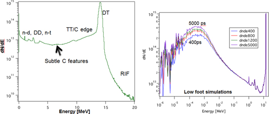
Figure 52. Simulated neutron spectra of NIF layered target implosion.
Download figure:
Standard image High-resolution imageThe present diagnostic challenges due to backgrounds that prevent measurement of RIFs and LENS can be greatly reduced by placing two unique (low and high energy) NTOF detectors at 100 m (figure 53). The left-hand figure shows that the late time signal in an NTOF detector is dominated by a nearly constant-in-time gamma ray background. This contribution arises since the detector is too large to effectively suppress gamma ray detection. Thus, the new LENS system should have small volume individual detectors or pixels to suppress gammas while effectively detecting low energy neutrons. As an example, 2 × 2 × 5 mm pixels of 10%-borated plastic scintillator would have a high detection efficiency for thermal neutrons while being essentially blind to gamma rays. Figure 53 (right) demonstrates that the portion of the NTOF signal in the RIF energy (time) region is contaminated by background gamma rays from 14 MeV neutron interactions upstream in the line-of-sight; the gamma ray time-of-flight is less than the nToF to the detector. This portion of the spectrum needs to be reduced by 10−5–10−6 (relative to the primary DT peak) to measure the RIF spectrum to ∼10% statistical relative uncertainty. By placing the detector far away from scattering sources at 20 m, the leading edge of the time-of-flight signal has substantially less background. A carefully designed beamline has been shown empirically to be clean down to the ∼10−5 level. Placing the detector farther away from the TCC would reduce the background to levels meeting the measurement requirements.
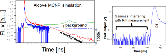
Figure 53. Backgrounds that interfere with measuring subtle neutron spectrum features (left) simulation of a NIF DT shot showing the neutron (red) and photon (blue) flux arriving at the detector. The time-transformed 6Li(n, α) cross section is plotted for reference with the 240 keV resonance clear between 3000 and 4000 ns. (Right) measured alcove NTOF signal from a direct drive exploding pusher shot, illustrating early-in-time gamma backgrounds on the NTOF signal.
Download figure:
Standard image High-resolution imageA high resolution, full spectrum NTOF spectrometer (figure 54) consists of two separate detectors at roughly 100 m from TCC. The beamline will consist of three upstream collimators: one at the TC, one at the TB wall, and one at the building wall. A rough vacuum line-of-sight tank will be required to minimize low energy neutron capture/attenuation in the roughly 70 m of air (air attenuation is only a minor concern for high energy neutrons). The first detector is a LENS situated 100 m from TCC on the equatorial plane of the NIF. The detector consists of highly segmented or crossed fiber boron-loaded scintillator arrays. The scintillators are readout by segmented PMTs and VME digitizers, and are expected to operate in pulse event-by-event mode. The HENTOF detector will consist of a roughly 50 cm diameter slab (or segments) of bibenzyl (like the ones currently used in the 20 m spectrometers [195]) or equivalent organic scintillator that is viewed by 8 PMTs producing excellent sensitivity down to 1 MeV, covering several orders of magnitude in neutron yield. This detector should be situated >20 m downstream of the LENS. Ideally there will be a small collimator between the LENS and the HENTOF to eliminate some of the scattered neutrons/gammas from neutron interactions on the LENS. The HENTOF will operate in current mode, in much the same way as the existing 20 m spectrometers at NIF do.
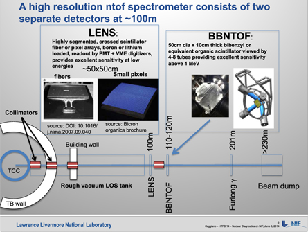
Figure 54. Schematic layout and detector concept.
Download figure:
Standard image High-resolution imageA LENS uses boron-loaded scintillators to detect low energy neutrons with high sensitivity. As an example, consider figure 55 which is a simulation for a 'High Foot' shot at 1016 total yield. The figure depicts the number of neutrons incident upon the detector in each time bin; notice that the number of neutrons in the 10–100 eV window is substantial (103–107) depending on whether it was a low or high ρR shot. With a 1%–10% detection probability in these windows, the signal is measurable. Further, the high segmentation allows for a higher detection rate than normal and thus mitigates most of the possible pileup. If small pixels are used, 2 × 2 × 5 mm, the average 1 MeV photon makes only 12 keV electron-equivalent light, while the 4 MeV alpha from the 10B(n, α) reaction produces 200 keV electron-equivalent light. Thus, a threshold can be placed on the pulse train excluding virtually all the gamma ray hits in the detectors. Another background suppression feature is a 'beam dump' located far downstream, which will substantially reduce the signal backgrounds at late time; however, the requirements on such a 'beam dump' can be relaxed substantially due to the insensitivity of the detector to gamma rays.
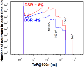
Figure 55. Neutrons incident on a 50 cm diameter detector from a 1016 total yield high-foot shot.
Download figure:
Standard image High-resolution imageUtilizing the HENTOF, the RIF neutron spectrum measured at 120 m is cleaner and provides 500% better resolution than measurements at 20 m. The high energy neutrons are produced by two mechanisms that are most interesting: alpha knock-on neutrons (AKN) (neutrons from alpha-up-scattered d, t) and RIF neutrons (neutrons from 14 MeV neutron-upscattered d, t). Of special interest are the AKN which may be a sensitive indicator of alpha heating in the cold fuel shell, a necessary condition for achieving ignition. Figure 56 (left) shows that DT secondary neutrons only extend to about 18 MeV for temperatures of interest to NIF. Beyond that, the spectrum is clean and is dominated by AKN (up to about 21 MeV) and RIF (up to about 32 MeV) [196]. For neutrons in this energy region, a 20 m NIF neutron spectrometer has an energy resolution of about 3.3% and therefore compromises the spectrum measurement (figure 56 (right)). However, a similar detector operating at ∼100 m would have a resolution of 0.7%, yielding better measurement of the neutron energy spectrum details in that region. The higher energy resolution would allow better separation of the AKN compared to the RIF neutrons.
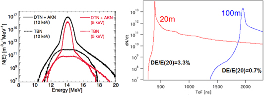
Figure 56. Neutron spectral features in energy and time.
Download figure:
Standard image High-resolution imageNote that the gamma background in the AKN/RIF window is dramatically reduced by moving the detector far from the scattering sources.
In addition to adding a measurement capability above 15 MeV, the HENTOF detector will measure the standard ICF parameters with much higher accuracy. It should be noted that the core of the IRF will be comparably narrow (∼4 ns), so that the DT Tion measurement becomes more accurate since the width of the peak is now so much larger than the width of the IRF (intrinsic resolution).
4.2.2. Compton gamma spectrometer
A Compton gamma spectrometer, named as the GEMS has been designed to enable the measurement of the prompt γ-ray energy spectrum during high yield DT implosions at the NIF [96, 197]. One example of the prompt γ-rays includes the 16.75 MeV γ-ray line from T(D, γ)5He, which provides a direct signature of the total DT fusion yield. Another example is the 4.44 MeV γ-ray line from 12C (n, n'γ)12C, which is created when energetic DT fusion neutrons inelastically scatter on their way through the plastic capsule ablator. The intensity of the 4.44 MeV is thus directly related to the areal density of the capsule [95]. The prompt γ-ray energy spectrum will provide 'burn-averaged' observables, such as the total DT fusion yield and the total areal density (ρR). The burn-averaged observables from the γ-ray spectrum are unique because these observables are essentially averaged over 4π about the implosion and do not depend on the line-of-sight to measurement devices. Therefore, the GEMS observables will provide a global reference for the line-of-sight-specific measurements, typical of x-ray and neutron diagnostics. The schematic of the GEMS shown in figure 57, consists of a Compton converter (e.g., beryllium), electromagnet, and an electron detector array placed at the focal plane. Incident γ-rays from the implosion target scatter electrons out of the converter plate primarily through Compton scattering [198, 199]. The Compton electrons enter an electromagnet where energy selection takes place. The dispersed electrons enter Cherenkov radiators (e.g., fused silica) where their binned energy is converted to UV/visible photons for detection by photomultipliers (PMT). The GEMS will require ∼5 × 10¹⁴ minimum DT neutrons to measure 4.44 MeV 12C γ-rays at 200 mg cm−2 areal density and ∼2 × 10¹⁵ minimum DT neutrons to measure 16.75 MeV DT γ-rays.
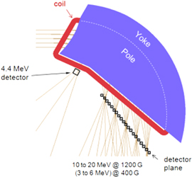
Figure 57. A schematic drawing of the GEMS (gamma-to-electron magnetic spectrometer) magnet and detector array. Reprinted with permission from [197], Copyright (2014), AIP Publishing LLC.
Download figure:
Standard image High-resolution image4.2.3. Gamma imaging system
X-ray and neutron self-emission images provide diagnostic information useful for determining the hot, reacting volume in ICF experiments. Complementary to these images, gamma ray and scattered neutron images are useful for diagnosing the size and shape of the non-reacting material, which provides insight into the symmetry and integrity of the shell compressing the hot core. Figure 58 illustrates these concepts. Starting with the innermost volume, free-streaming 14 MeV neutrons may be aperture resolved and converted to light in a scintillator which is then recorded by a time gated digital camera, resulting in a projected image of the region where fusion reactions are occurring. If the neutrons elastically scatter to lower energies, which is occurs predominantly in the dense DT shell surrounding the reacting volume, a second camera with a delayed time gate may be used to record the projected image where neutrons are scattering. Finally, if the neutrons undergo inelastic collisions, which excite nuclear levels in a nucleus, e.g. 12C(n, n')12C*, where the 12C* promptly decays by emission of an MeV scale gamma ray, then a third camera system may be used with an advanced time gate that produces an image of the outer ablative shell tamping the DT assembly.
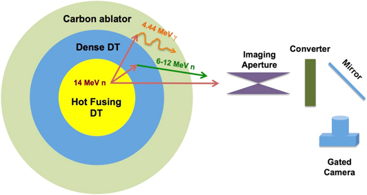
Figure 58. Nuclear processes that may be exploited to image the compressed target assembly in ignition experiments at the NIF.
Download figure:
Standard image High-resolution imageNeutron and x-ray imaging have been discussed previously in this article, but it should be recalled that neutrons scatter in the 'hot spot' and the cold fuel regions, as well as the lower areal density carbon ablator. The image brightness (signal) in each element will be reduced at larger radii due to the decreasing flux, and in the case of the carbon ablator, at lower areal density. Simulated gamma images of the carbon ablator show that these images extend to a much larger radius than that of the cold fuel and provide diagnostic information on the measure of compression of the unablated shell.
The size and shape of the remaining ablator material during burn is important to ignition experiment design. If too much ablator mass remains, the implosion will evolve more slowly and generate less internal energy than desired. If too little ablator mass remains, instabilities will result, potentially tearing apart the tamper and compromising the nuclear performance. The ability to assess the size, shape, and remaining mass of the ablator is therefore useful when diagnosing hydrodynamic performance of the experiment during burn.
As mentioned, imaging the remaining carbon ablator material is possible via the inelastic scattering of neutrons on carbon, especially 12C(n, n')12C*, which will populate the first excited state of the 12C nucleus as depicted in the level scheme of figure 59(a). As shown by the blue arrows in figure 59(a), the transition to the ground state results in a 4.44 MeV gamma ray. These gamma rays are emitted virtually isotropic, as shown by figure 59(b) and can be imaged through apertures designed for neutrons. Evaluated nuclear data estimates for the cross section at 14 MeV for this reaction are approximately 200 mb. Simulation and experimental estimates of the remaining ablator during burn are about 200 mg cm−2, resulting in approximately one 4.44 MeV gamma for every 500 neutrons passing through the ablator. Although this signal rate is slightly less than the observed rate in down-scattered neutron images, it is necessary to use signal multiplexing apertures and a more sensitive radiation converter to obtain the desired gamma-ray image.
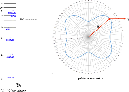
Figure 59. (a), (b) The experimental level scheme for 12C and the theoretical angular emission pattern for the resulting 4.4 MeV photon.
Download figure:
Standard image High-resolution imageResearchers at Los Alamos National Laboratory have studied the feasibility of imaging 4.44 MeV photons and have developed a conceptual design for a gamma imaging system at the NIF [200, 201]. In addition to the physics requirements, the principal constraints were to minimize the cost and the impact to the existing NIF imaging diagnostic suite. This work concluded that the penumbral apertures within the NIF NI system were sufficient to provide images with peak signal-to-noise estimates larger than 20 for shots with neutron yields greater than 1015.
A gamma imaging proof of concept test was performed on the NIF shot N150518. The NI system gates were configured to collect images of primary 14 MeV neutrons and gamma rays interacting in the radiation converter. Figure 60(a) shows the raw image of 14 MeV neutrons through the NIF NI aperture [92]. The image clearly shows the 20 pinhole images and 3 penumbral images. Since the penumbral apertures are large bores with a diameter larger than the source, the resolved neutron fluence is coded into the penumbral portion of the image, requiring a computed tomographic analysis [202] to reconstruct the source. Figure 56(b) shows the image of high energy photons interacting in the converter. Since the converter does not have energy resolution and the camera gate integrates all energies of photons, studies of backgrounds, such as LPI hard x-rays, are required to fully interpret the observed signal. Since the mean free path of the MeV scale photons in the gold aperture assembly is about 1.5 cm, the effective diameter of the neutron pinholes is less than 1 μm, providing a solid angle that is too small to produce useful gamma images, which is confirmed in the figure. Further, since the penumbral apertures have a field of view of about 250 μm, and the aperture is collecting neutron images, the source of the radiation observed in the penumbral images of figure 60(b) must be either from the compressed target, or from inelastic neutron interactions along the aperture line-of-sight and within 1–2 m of the target. This latter source was ruled out in a subsequent experiment using an IDEP, which contains all the same line-of-sight materials as shot N150518, but did not have the compressed carbon present to produce 4.44 MeV gammas. This experiment confirmed that the signal collected in figure 56(b) was from high energy gammas being produced in the compressed target assembly.
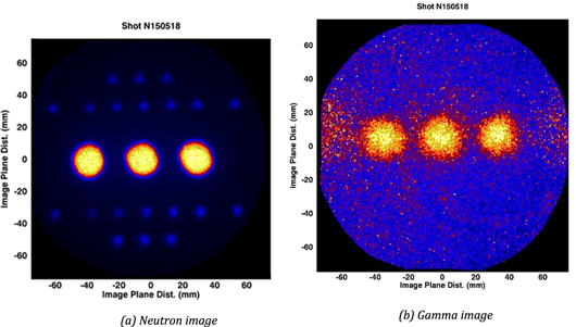
Figure 60. (a), (b) Raw 14 MeV neutron image and gamma image from shot N150518 at the NIF.
Download figure:
Standard image High-resolution imageThe conceptual design of a gamma imager on NIF is shown in figure 61. Radiation from the implosion passes left to right through two radiation-to-light converters, with the left most being a coherent array of organic (BCF-99-55) scintillating fibers to image neutrons, and the right most, a coherent array of LYSO crystals to image gammas. The flight path length to these converters is approximately 28 m, resulting in arrival times of roughly 90 and 540 ns for the gammas and neutrons produced at bang time, respectively. This allows fast, O (10 ns) MCP image intensified gated camera systems to image the light from the corresponding converters. Since scintillation light travels both left and right in the figure, two cameras may be employed to add a framing camera capability to the imaging system.
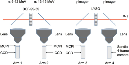
Figure 61. Design concept for a gamma imaging system in the NIF neutron imaging line-of-sight. This configuration, or facsimile, will be implemented in the equatorial neutron imaging lines-of-site, located in NIF polar coordinates at (90, 315) and (90, 213).
Download figure:
Standard image High-resolution imageStarting in 2018, the NIF will field a dedicated gamma ray imaging system, comparable to that shown in figure 61. The goal of the system will be a measurement of the thickness and uniformity of the carbon ablator that remains at peak neutron production time. The shell uniformity of density and thickness is important to the success of obtaining ignition on the NIF, and an excellent metric for validating current predictive tools. Considerable work has been done to demonstrate the viability of a gamma imaging system with prototype detector systems already developed and tested at HED facilities, such as Omega, and at the High Intensity Gamma Source at the Duke University FEL [203]. The necessary image reconstruction algorithms are available to invert the coded aperture source [204–206].
4.3. Proposed research at the NIF and at complementary facilities
4.3.1. Charged particle reaction studies at the NIF and complementary at accelerators
It has been demonstrated that a HEDP environment with high neutron fluencies at keV temperature and high density conditions in the short pulsed (ps) time domain is routinely achievable at the NIF (see section 2). There is increasing interest in developing a scientific program to utilize these conditions for nuclear science and more specifically for nuclear astrophysics research at the NIF. Several start up projects and research opportunities have been identified in international workshops (e.g. see [207] and are summarized in an NNSA White Paper [208]). A proposed experiment and precursory effort are focused on the measurement of the 10B (p, α) 7Be nuclear reaction rate in the HEDP environment to better than 20% accuracy. The study will be primarily based on the measurement of the characteristic activity of 7Be that needs to be collected with high efficiency by collectors positioned near the capsule. This effort is complementary to ongoing accelerator experiments at the University of Notre Dame. These experiments provide accurate benchmark data that are essential for astro-physical cross section networks and theory; the 10B (p, α) 7Be reaction study is also of interest to aneutronic fusion reaction studies. The HEDP environmental conditions in a NIF shot, are determined by ICF oriented diagnostic data for DT fusion and corresponding modeling assumptions. The NIF based reaction rate data can in turn, be utilized for mapping and understanding of the shock dynamics that determines the thermal energy distribution (e.g. Maxwellian). The experiments new tool for innovative nuclear science experiments will open the pathway for lower cross section reactions such as the important 3He (α, γ) 7Be reaction in nuclear burning in our sun [209] that defines the solar neutrino flux.
The NIF produced plasma mimics the conditions of the stellar interior, yet the time-scale is dramatically different. Measuring and interpreting nuclear reactions of nuclear astrophysics relevance constitute a fundamental challenge [210]. It is therefore essential to establish benchmark reactions, for monitoring the development of temperature, density and other parameters in the NIF environment. This enables the conversion of reaction data to stellar cross sections and rates, for nucleosynthesis simulations and for scaling of future nuclear reaction measurements. These experiments would also be the first opportunity to test theoretical assumptions about stellar plasma screening which so far only rely on accelerator experiments on low temperature, low density gases.
Nuclear reactions in stars are dominated by charged particle interactions at very low energies that are typical for quiescent stellar burning conditions. The cross sections corresponding to the stellar temperatures are too low to be reliably measured at present accelerator facilities and rely strongly on the extrapolation of existing higher-energy data towards the stellar energy range [211]. It was demonstrated in very low energy experiments at 'background free' underground laboratories, that atomic screening effects cause an enhancement of the reaction yield [212]. On the other hand, reactions between completely ionized nuclei in stellar plasmas are subject to plasma screening through the free electron cloud that will modify the reaction cross section compared to accelerator laboratory data. Screening affects the time scale, the energy production and the nucleosynthesis associated with the specific reaction in question. The standard treatment of the screening conditions relies on the theoretical Debye–Hückel formalism that has not been tested experimentally [213]. The 10B (p, α) 7Be reaction provides a perfect case for testing screening predictions. Initial accelerator work has been done at low energies [214]. The cross section is relatively large, due to the contribution of a resonance at 10 keV, and the possible impact of screening has been evaluated. Complementary to this effort, indirect measurements have been done using the so-called Trojan horse method to probe the nuclear reaction cross section on bare 10B nuclei [215]. From the experimental point of view the reaction product 7Be has a considerable advantage since it does not occur naturally in nature, and it can be relatively easily collected and detected as a shot product.
The measurements of charged particles at the NIF require loading the target capsule or capsule shell material with the needed target material such as hydrogen and heavier mass material. Similar platforms as described in section 2 are then used for the reaction rate measurements.
For the 10B (p, α)7Be experiments the ablation/compression scheme, which heats the target material inside the capsule, is achieved in a direct polar drive configuration (less compression) or in a hohlraum utilizing the 300 eV ablation plasma (more compression). The experiments require reaching a Maxwellian averaged temperature of about 20 keV. For some precursor experiments a very limited DD neutron production can be used as a thermometer. The approaches to achieve stellar burn or ICF are similar except that for stellar burn reaction studies [216] higher number densities of reacting target atoms can be used (e.g., 1019 atoms of target material in the capsule).
Thermal temperatures of about >20 keV can be reached in a special designed NIF target capsule containing sufficient mass of the reaction constituents of ionized 10B and H in a plasma. The proposed 10B/H plasma target would provide a high-density target with a number density of about >1018 bare 10B and protons, where about 1015 could reach temperatures of ≤40 keV. The target material could either be doped in the shell material or it could be the gas load in a capsule with specified shell material.
The first phase of the approach is an evaluation and optimization of the target configuration using advanced hydro-dynamic simulations. As an example, the following configurations will be evaluated: an exploding pusher configuration could be used, where ablation of a low Z-outer shell drives a high-Z inner shell, containing the 10B/H, inward and thereby moderately increasing the areal density and raising the temperature. The maximum temperature is reached at the point of maximum shock compression as the spherical target converges. The lasers resemble a configuration close to a spherical symmetric direct drive (no hohlraum) with lasers impinging on the target directly from two hemispheres; a configuration utilizing a hohlraum will be simulated as well. Practically the high-Z metal inner-shell shell (e.g. Au) contains 10B2 H6 (di-borane) and the shell is coated with a lower-Z outer-shell (CH plastic) as pusher; this should heat the 10B/H plasma target to high temperatures (in hohlraum or direct drive configuration).
Simulations for the target capsule scheme and drive configurations will be performed to optimize a possible laser drive and target configuration in terms of the achievable temperature and target density.
An estimate of the reaction rate for the 10B(p, a)7Be reaction using a 1D hot spot model gives yields in the range of Y ∼ 104–105 (assumptions: number densities N of 1020 cm−3, reactivity 〈σv〉 of 10–20 cm3 s−1 (Tion ∼ 30 keV), hot spot volume V of 10−6 cm3, burn width Δt of 10−10 s); the reaction yield is given as YC = Na Nb 〈σv〉 VHS Δt, (figure 62). (Note: the reaction rate in the thermalized plasma (high areal density) is R (a + b, NIF) = 〈σab v〉 AV ρa ρb V t(s); the rate at an accelerator for a specific beam energy is R (a + b, accelerator) = Ia σab Nb Δx.)
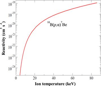
Figure 62. Reactivity versus ion temperature 10B (p, α)7Be.
Download figure:
Standard image High-resolution imageThe measurement of the reaction rate for 10B (p, α) 7Be as a benchmark requires the development of an efficient 7Be collection capability which will enable the reaction rate measurement with good accuracy for the very low (<nano-barn) cross section reaction 3He (4He, γ)7Be from the solar H-burn (p–p) reaction scheme for further evaluation of the standard solar model.
The proposed scenario for the collection of 7Be from the 10B (p, α) 7Be and later the 3He (α, γ)7Be reaction is briefly described (the decay of the 3/2-state in 7Be is depicted in figure 63). Figure 63. Decay scheme of neutral 7Be. Download figure:
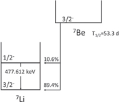
As an example for precursor experiments radioactive (4 micro Curie) 8Be is mounted at the hohlraum in DT ICF shots to determine the collection efficiency in ride-along shots. A collection calibration method for the collection efficiency is developed utilizing targets, loaded with Au/Xe and/or DD with known (n, γ) cross sections in a shot prior to the shot with the none neutron producing 10B/H-target. This baseline experiment allows the reaction rate to be measured relative to the well-known DD reaction cross section.
Other possibilities for the 7Be collection could include a 'gas catcher system' with collection of the 7Be in an increased Xe background gas in the NIF chamber (e.g., a small exploding cry-coated xenon shell in the target vicinity or filling the whole NIF TC with low pressure xenon to stop and catch the reaction products). We can use the established radiochemical gas analyzing system (RAGS) following a shot. These possibilities are under consideration including an efficiency evaluation.
Development of a high efficiency collection system for non-noble gas reaction products from the exploding target capsule for NIF is a focus of the radiochemical diagnostic at the NIF. The development will enable various other programmatic experiments at the NIF. The development of the overall experimental capabilities (e.g. diagnostic, target, laser conditions) will support a variety of nuclear astrophysics reaction studies, but also demonstrate a target capability useful for stockpile-steward ship programs as well as applied physics programs (e.g., intense neutron source developments involving high density, high temperature non-ignition targets).
Complementary to the reaction rate measurements at the NIF, detailed low energy measurements at the Notre Dame NSL are being performed. Comparison of the rate data allows quantification of the screening effects for the low energy cross sections of the selected benchmarking reactions. Figure 64 shows a recent plot of experimental and theoretical cross sections for 10B(p, α)7B; new accelerator based data and comparison to theory are in progress at ND. The facility is optimally equipped for low energy nuclear reaction measurements with stable and light radioactive particle beams [217]. These experimental conditions are optimized for performing the proposed reaction studies using complementary in-beam gamma ray spectroscopy methods with the high-resolution Germanium-detectors as well as off-line activity. The experimental data are analyzed and fit with the multi-channel R-matrix code AZURE [218] that was recently developed by the Notre Dame group and has been used successfully for extrapolating low energy reaction cross sections with high precision by parallel fitting of multiple reaction channels. This combination of low energy measurement and R-matrix extrapolation of data over a wide energy range has been shown to be extremely successful in reducing the low energy uncertainties. The 10B(p, α)7Be the reaction cross section is characterized by broad resonant and non-resonant components, where the extrapolation requires a careful analysis of the interference patterns in the multi-channel approach [209]. Characteristic low energy pattern and the deviation of accelerator based 7Be yield and shot based 7Be yield may serve as signature for mapping plasma screening effects! The relatively long half-life of T1/2 = 53 days makes it an interesting case for diagnostic use by activity measurement. The identification of interference patterns could provide an excellent signature that can be used to extract the plasma conditions during the shot period.
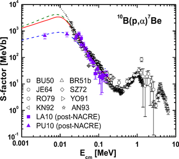
Figure 64. Experimental and theoretical cross section (NACRE II: an update of the NACRE compilation of charged-particle-induced thermonuclear reaction rates for nuclei with mass number A < 16 [219]).
Download figure:
Standard image High-resolution imageNuclear reactions with low energy light ions (1–50 keV) and atomic targets with bound electrons, show a cross section enhancement from a lowered Coulomb barrier due to screening compared to a bare nucleus target. Enhancements due to electronic screening effects are expected to be present in stellar plasmas as well. The screening effects increase with decreasing reaction (Gamow) energies but are small and a quantification requires a high accuracy (>10%) for the cross section and S-factor measurements.
4.3.2. Using (α,n) reactions to study alpha particle heating of fusion DT Fuel plasmas
The DT fusion reaction results in the emission of a neutron and an alpha particle (4He), that is, D + T → n + 4He, with the release of 17.6 MeV of energy in the form of kinetic energy of the neutron (14.1 MeV) and the alpha particle (3.5 MeV) [220]. The ICF concept as described above (section 1) generates high temperatures and pressures creating a HEDP in which the fusion takes place. The spectrum of neutrons escaping from the ICF capsule is a rich indicator of the conditions and properties of the hot dense plasma and its environment. In contrast, most of the alphas that are created in the ICF implosion do not escape from the tiny hot core, and those that do are quickly stopped in the cooler, less dense fuel plasma immediately adjacent to the core. Nevertheless, these alphas play a crucial role in the working of an ICF capsule. The alpha particles, born with 3.5 MeV of energy, return that energy to the plasma core and the nearby cooler fuel as they slow down, continue to heat the core and fuel, and help create the burn front (and burn wave) that can lead to ignition in future ICF designs (see, e.g., [221]). Despite their importance, there are almost no direct measurements on or diagnostics of these alpha particles in HEDPs. Their travel distance in the ICF capsule is just far too short to effectively detect them by external diagnostics.
A critical, and essentially unmeasured, aspect of alpha particles is their stopping power in a HEDP. Recent theoretical investigations of alpha particles in plasmas have been carried out by a number of investigators [151, 156, 222]. Though all of these models share the same foundational physics to a large extent, the choice of terms included in the models, and approximations to express these terms, lead to differences in calculated alpha stopping power in a HEDP, and, hence, to travel distance, to energy loss, and to distribution of energy loss among electrons and ions. Recently a key step towards ignition in an ICF capsule was taken for the first time [223] in experiments (the 'high foot' campaign) at the NIF where the energy produced by the DT fuel exceeded the energy deposited by the compression process into the fuel and hot spot; the fuel gain was close to 1. A significant part of the improved fuel gain for these shots involved the amount of yield deduced that is attributable to alpha self-heating, that is, the additional yield resulting from the return of 3.5 MeV of alpha kinetic energy to heating the plasma and resulting in more fusion. The ratio of the alpha self-heating yield to the compression yield was almost 1 for one high foot shot. A follow-on phase of the high foot campaign [224] replaced the gold (Au) hohlraum with a DU hohlraum. Significantly, the yield amplification (the ratio of the sum of the compressive yield and the alpha self-heating yield to the compressive yield) was about 2 for several high foot shots with DU hohlraums, compared to 1.7 with the Au hohlraum. The improved overall performance with the DU hohlraums, mostly due to opacity changes, enabled higher implosion velocity, more compression, and rounder implosions [224]. The inferred alpha self-heating and yield amplification, however, have not been causally tied to these or other measurable quantities.
For the alpha particles, the fraction of energy deposited in the hot plasma core, fα, was calculated to be in the range from just above 60% to 80% for several of the high foot shots [223]. A separate analysis [225] calculated that for a high foot shot fα was about 56% and the fraction of alpha particles absorbed in the small hot core was 62%. Inferences such as these, the growing importance of alpha self-heating, and the fact that alpha stopping models have not been experimentally tested, suggest that quantifying alpha particle populations and their spectra in HEDPs would be informative.
Radiochemical activation experiments have the potential to provide useful information on alpha particles in HEDPs. For example, a small amount of target material mixed with a portion or all of the DT fuel could be activated via the (α, n) or (α, p) reaction, collected as a gas or solid, and the product's radioactive emissions counted to determine the number of reactions that take place [226]. Another class of experiment that exploits the short range of the alpha particle is a mix experiment where the detector material is added to the capsule shell, either uniformly or as a thin layer on or near the inside surface. Activation of this material could indicate a deep mixing of the capsule material through the bulk of the cold fuel to just outside, or even into, the hot spot [227].
The rest of this section concentrates on the possibility to use the 10B(α, n)13N reaction to assay alpha particles in or near the small hot core of the implosion. The (α, n) reaction with 10B has suitable nuclear reaction energetics (see table 4), and its cross section increases up to about 25 mb as the alpha energy increases toward 3.5 MeV, enabling the 13N product nuclei to be made in adequate numbers. In addition, 13N is a gas, and assuming the plasma chemistry produces mainly N2, can be collected with efficiencies approaching 100% with the RAGS system [6, 228]. The 13N half-life is a convenient 10 min. When needed, 15N could be used as a tracer gas. A drawback of 13N is that it decays by positron emission resulting in two 511 keV photons, which is also a typical decay mode for other light gaseous reaction products that might be formed at NIF. Fortunately, the half-lives of these other products are sufficiently different from that of 13N that the 511 keV photo-peak decay curve can be successfully de-convoluted to extract the portion due to 13N.
Table 4. Nuclear data [229] and information for potential targets and (α, n) products that could be used to detect and assay the alphas resulting from the DT fusion reaction in a NIF target are summarized.
| Target | (α, n) product | Threshold (MeV) | Coul. bar. (MeV) | Half life (s) | Radiation | Chemical form | Sigma at 3.5 MeV (mb) |
|---|---|---|---|---|---|---|---|
| 10B* | 13N | 0.00 | 2.4 | 598 | β+ | Gas | 25 |
| 12C | 15O | 11.34 | 2.8 | 122 | β+, ε | Gas | 1 |
| 14N | 17F | 6.09 | 3.2 | 65 | β+ | Gas | 6 |
| 18O* | 21Ne | 0.85 | 3.4 | Stable | None | Gas | 110 |
| 19F* | 22Na | 2.36 | 3.8 | 8.22 × 10⁷ | β+, ε, γ | Solid | 35 |
| 27Al | 30P | 3.03 | 5.1 | 150 | β+, ε, γ | Solid | 27 |
| 29Si* | 32P@ | 2.79 | 5.4 | 1.23 × 10⁶ | β− | Solid | — |
• Identified as possible mix detectors [10]. @ (α, p) product.
The RAGS system was developed to collect, separate, purify, and prepare gas samples for in situ gamma-ray counting or transfer to a gas bottle for remote assay [6, 228]. It has demonstrated the collection of fission noble gases with half-lives ranging from 9 s to 2.8 h, as well as 19O (27 s), 18F (110 min), and 23Ne (34 s) at detector locations next to system getters, traps, and chambers. The 18F radioactivity is used to characterize the pumping speed for gases from the TC to the RAGS system; the time to pump half of the remaining gas is found to be 180 s. Recently 13N, believed to be from (D, n) reactions on the carbon capsule shell, has been collected on the hot getters, and observed with RAGS system detectors [185].
Several radioactive gases that decay via positron emission are made from isotopes that are often part of, or near, the ICF target. Some are made by the (n, 2n) reaction, while others may be produced by deuteron or proton reactions on materials in the capsule. 13N radioactivity occupies a 'sweet spot' between those that have half-lives of about 2 min or less, and 18F which has a half-life of nearly 2 h and thus can be distinguished from most interfering activities. Particularly troublesome are those materials and reactions that produce 13N from isotopes other that 10B, as they are indistinguishable from the desired 10B (α, n)13N reaction product. Plastic (CH) shell capsules are often used for ICF experiments and higher energy deuterons from the plasma or high energy protons generated in the plastic by neutron scattering of hydrogen [185] can produce 13N. Thus plastic ablator capsules cannot be used in experiments using boron; beryllium or glass capsules should be suitable. The estimated production of 13N from residual 14N in the TC is low; this is supported by the measurements on shots without CH capsules [185].
Several methods have been devised for loading radiochemical detector material into ICF capsules, and might be used to incorporate boron into capsules using these methods. For example, two layers of the element xenon, each with a different isotope, have been incorporated into capsules for ρR studies [228]. Other materials, such as silicon and germanium, are regularly incorporated into plastic capsules to provide x-ray emitting layers for a variety of x-ray diagnostics. Other ideas, such as aerogel foam layers to hold a material, and direct chemical deposition of materials on the inner surface of the capsule, are being explored. Direct incorporation of gases species (such as di-borane (B2H6)) into the DT gas fill may be possible in some circumstances. Effort will need to be invested in any of these capsules to assure that they can be fabricated, and models will have to help assess if the placement and quantity of boron can be characterized at the time of maximum fusion burn.
Finally, execution of the experiment with the RAGS system to utilize the 10B(α, n)13N reaction to diagnose the alpha particles from DT fusion involves a series of straightforward steps: (1) a capsule with 10B is placed in the TC; (2) fusion produces alpha particles that react with boron to produce 13N; (3) 15N tracer is injected into the TC; (4) the 13N is assayed in situ at the appropriate RAGS system component; (5) all the nitrogen is transferred to a removable transfer sample bottle; (6) the 15N in the sample bottle is assayed by mass spectrometry to get the nitrogen collection fraction; and (7) the 15N results and the counting results for 13N are used to deduce the number 10B(α, n)13N reactions that occurred in the capsule.
Several research and development activities are important to performance of this (α, n) experiment. The successful fabrication of a capsule with boron appropriately incorporated is required. If di-borane is used, safe fabrication methods can be established because of the toxicity of this gas. The degree to which injected 15N gas is a robust tracer of 13N produced in the NIF capsule must be tested. The RAGS system should have modest upgrades to maximize trapping efficiency of 13N. A modern cross section estimate for the 10B (α, n)13N reaction is also needed. In addition, a successful experimental campaign will demand a substantial modeling and computational effort to extract physics knowledge and relevance to the NIF program.
The DT fusion alpha particle plays an essential role in the successful ignition of an ICF plasma. Experiments that obtain measured data concerning the DT fusion alphas will open an exciting window into the internal working of an ICF capsule.
4.3.3. Nuclear excitation in neutron-rich high energy density plasmas (NHEDP) at the NIF
Experiments at NIF offer the unique capability to study neutron-induced nuclear cross sections on nuclei in a high-energy density plasma environment [230–232]. In s-process stellar plasma environments, low-lying short-lived excited states can thermally be populated varying their spin (J) and parity. This may significantly alter the neutron absorption rate in branching point nuclei where such rates are comparable to their beta-decay rates, leading to altered population of predicted universal isotopic abundances [233–236]. Furthermore, NEEC [237–240] and nuclear excitation by electronic transition (NEET) [241–243] processes can occur on the highly-excited states produced by neutron absorption reactions before gamma emission, effectively 'hijacking' an (n,γ) reaction midway through completion [244, 245]. There are currently no existing capture rate measurements on plasma-excited nuclei, for any isotope. In addition, there are no measurements of nuclear reactions on non-isomeric excited states, as typical state lifetimes range from nanoseconds to picoseconds.
Interactions with neutrons in the plasma populate excited nuclear states. At NIF the dense environment and short fusion burn produces a high neutron flux, offering the opportunity to study rapid multi-step reactions impossible at any other laboratory. Current non-igniting NIF implosions produce 1015 neutrons over less than 100 ps in a sphere only 30 μm in radius. This neutron flux of 1029 n cm−2 s−1 is very high (exceeding that in supernovae) and is expected to be 1033 n cm−2 s−1 in igniting capsules. The combination of this immense neutron flux with high electron and photon density offers to study the atomic–nuclear interactions, such as NEEC and NEET, on short-lived, highly-excited states, with lifetimes on order of picoseconds.
An example of how nuclear processes can be affected in a NIF plasma is shown in figure 65, using 175Lu as an example 'seed' nucleus. A highly-excited nucleus may be created by (n, 2n) reactions from an approximate Gaussian energy distribution of fusion neutrons. The neutrons are centered at 14.03 MeV with a FWHM of about 400 keV, as produced in a typical non-igniting NIF capsule. This populates a range of energy levels in 174Lu just below the neutron binding energy, shown schematically in figure 65. In a non-plasma room temperature environment (e.g., an external activation foil), the intermediary nucleus de-excites by emitting a series of gamma rays. However, in a high-energy density plasma, electron and photon interactions will both excite and stimulate de-excitation at rates comparable to or greater than the normal decay lifetime. This broadens both the population of spin and energy states of the highly excited nucleus and shifts it upwards in energy due to the high state density gradient. If isomers exist at lower-lying states, decay cascades will populate these states differently due to the altered distribution. Furthermore, if sufficient energy shifting populates states above the neutron separation energy, a neutron may be emitted that was previously energetically forbidden. This effectively transforms the (n, 2n) reaction into an (n, 3n) reaction, producing 173Lu.

Figure 65. Conceptual diagram showing effect of high energy density plasma on an example nucleus of 174Lu, created by (n, 2n) reactions on 175Lu. Nuclear–plasma interactions broaden the populated states and shift it upwards in energy, changing the ratio of ground state (red) to isomer (blue) population or allowing an additional neutron to be emitted (green).
Download figure:
Standard image High-resolution imageMeasuring the effect of the plasma environment on nuclear reactions at NIF may require development and installation of new instrumentation. Long-lived solid products, such as from gold activation, can be collected with solid debris collectors, though increased solid angle capacity is likely needed. Out-of-plasma activation monitor foils are already deployable at several in-chamber locations near the implosion [231]. For the short-lived lutetium example described here, compact in situ gamma-ray detectors are needed, deployed both near solid debris collectors and activation monitor foils shielded from debris. Efforts are currently underway [230] to detect nuclear plasma effects in highly-excited 133Xe gas (produced from 134Xe (n, 2n) reactions), which can be collected using the RAGS diagnostic. The control 134Xe activation monitor is contained in gas cells [232] located on nearby DIMs.
4.3.4. S-process in HEDP environment (origin of the elements >A = 56)
Two main mechanisms are believed to be responsible for the formation of most of the elements heavier than iron (A = 56); the slow (s-) and rapid (r-) neutron capture processes. A significant amount of effort has been invested in modeling these processes and providing the nuclear physics data (cross sections, masses, β-decay lifetimes etc) needed for their interpretation. Direct measurements of the relevant nuclear physics parameters are difficult-to-impossible to perform since the s- and r-processes involve short-lived radioactive nuclei and take place in HEDP environments with temperatures greater than 20 MK and high particle densities. However, important nuclear physics issues that impact the s- and r-processes can be studied at new upcoming facilities such as NIF, FRIB and FAIR. Experimental data will provide for their incorporation into state-of-the-art astrophysical reaction network models. s-process branch point cross sections: The first of the issues addressed will be the formation of elements in the s-process. The s-process is the best-understood nucleo-synthesis mechanisms, with a weak component (56 < A < 100) acting in the cores of massive stars, and a main component (making A > 100 nuclei) acting in the helium burning shells of 'asymptotic giant branch (AGB)' stars. The s-process has two temperature components (kBT = 8, 25 keV) and takes place in plasma environments similar. The s-process proceeds slowly via a series of neutron capture reactions between stable isotopes along an isotopic chain until an unstable isotope is formed. If the lifetime of such isotope is long enough (>1 year), a 'branching' can occur where the (n, γ) rate forming the next isotope competes with its β-decay. Table 5 below shows the s-process path in the Tm–Yb region. These 'branch-point nuclei' carry important information on the temperature and neutron environments inside AGB stars. In addition, precise knowledge of the final s-process abundances is essential since they must be subtracted from the measured stellar abundances to determine the contribution by the r- and other processes.
There has been extensive work over the past two decades determining the 'Maxwellian averaged cross sections' for stable nuclei along the s-process pathway, particularly by the group at Karlsruhe [246–248] who have pointed out the need to determine the neutron capture cross sections on branch-point nuclei. However, to date, no capture cross sections have been measured on these nuclei due to the combined effects of the target activity and the low-intensity of neutron beams. A further complication in the extraction of (n, γ) cross sections on s-process branch-point nuclei is the fact that the process occurs in a dense plasma environment believed to induce the population of low-lying excited nuclear states. The latter results in different β-decay lifetime in the stellar environment. Takahashi and Yokoi [249, 250] have compiled tables to reflect these changes in β-decay lifetimes that are commonly used in nucleo-synthesis models. However, there is also significant uncertainty about the effect of populating low-lying excited states on the (n, γ) cross sections. Whereas for the ground states, the lifetimes of such highly-ionized systems can directly be measured in storage rings, the measurements of β-lifetimes of the exited states seems unrealistic at present. The difference in spin between the ground and excited states can be expected to induce sizable changes in low-energy neutron-induced cross sections. These changes in (n, γ) cross sections are generally parameterized in terms of a 'SEF' and are obtained using reaction model calculations that can have significant uncertainties greater than 20%–100%. Therefore, it is of utmost importance to search for experimental capabilities to benchmark the theoretical calculations
The s-process branch points at 170Tm and 171Tm are examples of a nuclei which could have their (n, γ) cross sections effected by thermal-induced population of low-lying excited states. The ground and first excited states of 170Tm and 171Tm are separated by 38.71 and 5.03 keV, respectively and have spin differences of 1ħ (see above). These states can be assumed to be strongly populated via nuclear–plasma interactions in the s-process environment with kBT ≈ 30 keV and densities greater than 100 g cm−3.
An ideal approach to improving the modeling of (n, γ) cross sections on s-process branch point nuclei would involve a combination of measurements at accelerators and ICF facilities. Significant progress has been made in the past several years in several accelerator-based techniques to improve the modeling of neutron capture rates using Hauser–Feshbach reaction via the measurements of the nuclear level density (NLD) and radiative strength function (RSF). Larsen and Goriely [251] have shown that even a modest enhancement in the RSF can lead to significant increases in neutron capture rates on neutron-rich Cd and Mo nuclei along the r-process path [252]. These experiments could include particle-gamma coincidence measurements of the NLD and RSF using the Oslo method which have already been used to inform neutron capture rate calculations in neutron-rich 242Pu [253], and decay-based beta-Oslo decay measurements that have provided similar insight into 75Ge(n, γ) [254].
A complementary ICF-based component would involve loading capsules with small quantities (≈1014–17 atoms) of radioactive target nuclides and collecting the reaction products post-shot to provide energy-integral validation of the capture cross section that include the effects of spin change due to plasma-induced excitations. Experiments to probe these effects are already underway at the NIF where nuclear–plasma interaction induced changes in the population of the 133Xe metastable state. Such experiments are ideally suited to DD and HT-fuel (proton + triton) loaded capsules that produces neutron energies that are more compatible with astrophysical reactions. The approach would involves implanting small quantities of a s-process branch point nucleus together with a neighboring stable isotope where the (n, γ) cross section has been measured in the stellar thermal energy region (kBT ≈ 30 keV) into the NIF capsule and measuring the production of the radioactive (n, γ) reaction products post-shot. The resulting ratio of capture products allows for the determination of the energy-integrated s-process branch point neutron capture cross section relative to the known stable isotope cross section. State-of-the-art simulations indicate that more than 85% of the neutron captures that occur in the NIF capsule will be due to near-stellar thermal energy neutrons (kBT ≈ 10 keV). Furthermore, the shot-integrated neutron fluence experienced by a nuclide seeded into an ICF capsule, which is of the order of 1019 n cm−2, is comparable to what would be found in the interior of the AGB star (≤107 n s−1 cm−2) over the course of more than 104 years. These energy-integrated cross sections include not only neutron capture on the ground state of these nuclei, but also on any low-lying excited states populated via nuclear–plasma interactions.
Table 5 lists the most important s-process branch point nuclei together with the energies of the first excited states. Nuclei likely to have thermal populations of low-lying excited states are indicated in bold face.
Table 5. Important s-process branch point nuclei. Potential STARS/LIBERACE reactions are in the right-most column.
| Branch point | Ground state Jπ | 1st exc. state Ex (keV) | 1st exc. state Jπ | STARS/LIBERACE reaction |
|---|---|---|---|---|
| 79Se | 7/2+ | 95.77 | 1/2− | 76Ge(6Li, d)80Se* |
| 85Kr | 9/2+ | 304.871 | 1/2− | 87Rb(d, 3He)86Kr* |
| 147Pm | 7/2+ | 91.1 | 5/2+ | 149Sm(d, 3He)148Pm* |
| 151Sm | 5/2– | 4.821 | 3/2− | 152Sm(n, γ')152Sm* |
| 163Ho | 7/2– | 100.03 | 9/2− | 165Ho(3He, a)164Ho* |
| 170Tm | 1− | 38.7139 | 2− | 171Yb(d, 3He)171Tm* |
| 171Tm | 1/2+ | 5.0361 | 3/2+ | 172Yb(d, 3He)172Tm* |
| 179Ta | 7/2+ | 30.7 | 9/2+ | 181Ta(3He, a)180Ta* |
| 204Tl | 2− | 414.1 | 4− | 205Tl(n, γ)205Tl* |
| 205Pb | 5/2− | 703.3 | 7/2− | 207Pb(3He, a)206Pb |
| 185W | 3/2− | 23.547 | 1/2− | 186W(n, γ)186W |
The combination of these measurements, e.g., at an accelerator and NIF would then allow a more complete understanding of the s-process and dramatically improve our ability to use the s-process to understand the mechanics and thermodynamics of the interiors of AGB stars.
4.3.4.1. r-process fission recycling
Another envisioned experimental activity is to study the formation of heavy elements in explosive nucleo-synthesis settings such as supernovae and the accretion disks around massive objects (black holes, neutron stars, etc). In these settings, extremely high neutron densities (>1022 n s−1 cm−2) and temperatures (kBT > 100 keV) form unique environments, where multiple neutron capture reactions can lead to a formation of extremely heavy nuclei far from the nuclear β-stability valley referred to as the r-process. At these densities neutron capture occurs regardless of cross section until equilibrium between (n, γ) and (γ, n) photo-dissociation is reached. These nuclei need to wait for β-decay converting a neutron into a proton prior to the process continuing. Under the given HEDP parameters, such as neutron densities and temperature, defining the energy of the photons, the location of these 'waiting points' is determined predominantly by the neutron binding energy in extremely neutron-rich nuclei. Once the conditions that initiate the r-process are through, the resulting neutron-rich products decay along isobaric, A = constant, chains via β-decay until a stable nucleus is formed. Also, the beta-delayed neutron emission, which cause a change to A-1, A-2, etc chains, needs to be considered.
In the heaviest nuclei formed (near A = 300) in the r-process also the β-delayed fission plays an essential role, which transforms the heavy nuclei back to middle-heavy ones. Recent work has indicated that this 'fission recycling' process could be responsible for most the nuclei near A = 135, 165. This process is highly dependent on the fission barriers and neutron separation energies of these very heavy nuclei, below shows the r-process pathway.
The HEDP environments where the r-process takes place will also induce a large population of low-lying excited nuclear states via NPI. These effects are more important here than in the s-process due to the correspondingly larger temperatures (kBT ≈ 100 keV versus 30 keV) and the photon and electron densities. However, since the r-process is explosive it is quite possible that many of these states will not be populated in a thermal fashion, requiring a better understanding of the cross sections of these processes themselves.
Processes that may play an important role in the heavier r-process nuclei are the NEEC, NEET (or inverse internal conversion (IC)) as described above for the proposed experiments. There a highly ionized high-Z atom absorbs a free electron into an inner electron shell and resonantly transfer the energy to excite a low-lying nuclear state. In order to facilitate experiments in the relevant energy, density and time domain various capabilities at the NIF need to be reliably established such as temperature diagnostic and the diagnostic of the neutron energy flux spectra all the way to the thermal spectral region (<1 keV). An envisioned first experiment scenario and a rough rate estimate are given in the following:
The fraction of neutrons below 1 keV differs by a factor of nearly 2.5 over this energy range. In addition to their value as a plasma diagnostic, (n, γ) reactions with keV neutrons are responsible for the formation of almost all of the elements heavier than iron made in astrophysical settings. These reactions occur via both rapid neutron capture in very high-flux environments (the r-process) and slow neutron capture in massive and AGB stars throughout their lifetime (the s-process). The s-process environment exposes 'seed' nuclei to neutron densities in excess of 107 cm−3 in stellar plasmas with temperatures from 0.1 to 1.0 billion degrees Kelvin (kT ≈ 8–86 keV). These capture processes take place at a rate defined by the neutron capture cross sections (σ (n, γ) ≈ 10−24 cm2) and the neutron velocity (vn): R(n, γ) =ρn vn σ (n, γ) = 0.1 yr−1. Neutron capture proceeds along a chain of isotopes for a given element until a radioactive nucleus is formed whose lifetime is comparable to or shorter than the capture rate. If the lifetime is significantly shorter, β-decay will occur. However, if the lifetime of the radioactive product is comparable to the capture rate, a branching takes place where β-decay and neutron capture compete.
Capture on 'branch-point' nuclei offers a unique window into the conditions in the interior of massive stars and plays a critical role in the development of stellar models [255, 256]. However, its usefulness is limited by a lack of knowledge of the neutron capture cross section on these radioactive branch point nuclei themselves. This need has been identified by the community and has led to a significant effort to determine these cross sections at astro-physics relevant energies.
4.3.5. Complementary studies of nuclear processes at heavy-ion storage rings
Investigations of nuclear physics processes in a HEDP environment is of utmost importance for our understanding of nucleosynthesis in stars. However, such investigations are highly complicated. It is therefore useful to perform dedicated studies of individual nuclear processes under isolated, e.g., outside of HEDP, conditions. Heavy-ion storage rings offer unparalleled possibilities for a range of such complementary investigations to unravel individual processes that take place in a complex HEDP environment.
4.3.5.1. Storage ring facilities and their properties
Presently there are three radioactive-ion beam facilities which have a possibility to store produced secondary particles in heavy-ion storage rings [257].
The chronologically first facility is built at GSI in Darmstadt. It consists of a combination of the heavy-ion synchrotron (SIS18), in-flight fragment separator (FRS) and experimental storage ring (ESR) [258].
The second storage ring facility, the experimental cooler-storage ring (CSRe) [257], is located at the Institute of Modern Physics, Chinese Academy of Sciences in Lanzhou, China. It consists of a heavy-ion synchrotron (CSRm), the in-flight fragment separator (RIBLL2) and the CSRe. Its operating principle is very similar to the one at GSI. At present, high-intensity beams of secondary, highly-charged ions are available for elements below about Xe. There is also no dedicated low-energy storage ring.
Another facility is the R3 storage ring at RIKEN [257]. The RIKEN facility is a superconducting cyclotron and a high-acceptance in-flight fragment separator. Due to the quasi-continuous primary beam from the cyclotron, the R3 is a dedicated ring to investigate single stored ions. One should stress, though, that the worldwide highest possible primary beam intensities are presently offered in RIKEN.
Considering the parameters of the available facilities, the one at GSI turns out to be the most suitable to address questions related to processes in HEDP.
Owing to high kinetic energies (up to 1.5 GeV/u) of the primary beams after the SIS18, secondary stable or short-lived nuclides can selectively be produced in high atomic charge states and stored for extended periods of time in an ultra-high vacuum of a ring [259, 260]. It should be stressed that by employing various separation methods in the FRS and ESR pure mono-isotopic or even mono-isomeric beams can be prepared [261, 262].
Cooling of stored secondary beams is indispensable for performing high precision experiments. So far, stochastic electron and laser cooling techniques were applied at the ESR to achieve high quality stored beams with momentum spreads of about 10−4–10−5 or even 10−6–10−7 for beam intensities of below about 1000 ions. Furthermore, the possibility to slow-down or accelerate stored beams permits tuning the experiment so that the specific process at a well-defined energy of interest is addressed.
Thin windowless internal gas targets allow for reaction studies with stored ions, e.g., of nuclear isomers, which bring several advantages compared to external target experiments [262]. Firstly, no background corrections due to target windows are needed. Secondly, the thin targets enable low-energy recoils to leave the target. Thirdly, cooled beams have small size and momentum spread which allows for measurements with very high spatial and angular resolution. Last but not least, high revolution frequencies in the order of a few hundreds of kHz to a few MHz result in accumulated luminosities that may be comparable or even exceed those obtainable in fixed-target experiments. It is important to emphasize, that, although the detection of target-like recoils and particle emitted in a reaction is limited by the covered solid angle around the target, the detection of projectile-like ions is done with a high efficiency. Depending on the type of the investigated reaction, even an ultimate efficiency of 100% can be achieved [260].
Detection of single stored ions with efficiencies close to 100% is one of the highlights of the in-ring decay spectroscopy, which allows nuclear decay studies on a basis of a single, highly-charged ion [259]. The sensitivity to single ions is successfully employed in the measurements of binding energies of very short-lived nuclides [258].
The ESR is a medium- to high-energy machine, which can store beams in the energy range of 4–400 MeV/u, which is defined mainly by the magnet power supplies. However, many physics questions, including those important in our present context, require significantly lower energies. Therefore, a dedicated low-energy storage ring, CRYRING, is being setup behind the ESR [263]. The CRYRING, whose operation was stopped at the University of Stockholm, was transported and re-assembled at GSI. The ESR-CRYRING combination will enable cooled, highly charged stored ion beams with energies from 400 A MeV down to energies as low as a few 100 A keV. The latter value is limited by the beam lifetimes, which decrease rapidly with lowering the energy.
The maximum intensity of stored radioactive ion beams is given by the production cross section, the nuclear lifetime, transmission from the fragment separator to the ESR as well as from the ESR to the CRYRING, and by the beam losses due to recombination in electron cooler or collisions with rest gas atoms. In-flight production of radioactive beams based on projectile fragmentation or fission is characterized by the separation times in the order of only a few hundred ns, while the production and separation are independent of the chemical properties of the ions of interest.
Access to fully stripped ions in the full energy range of ESR and CRYRING will be unique worldwide. Only about 10 s are required for cooling and slowing down of the ions in the ESR, making the combination of the ESR and CRYRING a very effective use of beam time. The ions of interest can be prepared in the ESR while the measurements are taking place in the CRYRING, enabling an efficient duty cycle. Furthermore, for sufficiently long nuclear lifetimes, the rare nuclides of interest can be accumulated in the ESR using existing techniques.
The electron cooler devices can be used as a free-electron target [261]. In addition, dedicated electron targets are being designed for ESR and CRYRING. Thus, investigations of highly-charged ions interacting with free electrons can be performed.
Both storage rings, ESR and CRYRING, allow coupling to laser beams. In the case of the ESR, this has been demonstrated by laser spectroscopy studies. A plan exists to transport to the ESR/CRYRING the high-power laser beam from the petawatt laser facility PHELIX. Thus, the stored ion beam provides a well-defined ion plasma suited for laser/beam plasma beam interaction experiments. The ion beams can also be extracted for experiments utilizing isotopic ion beam and external laser/plasma targets.
The unique experimental conditions provided by storage rings triggered several new projects worldwide.
At the future Facility for Antiproton and Ion Research, FAIR, which is being built as an extension of GSI in Darmstadt, a new complex of storage rings will further extend the capabilities of physics research with highly charged ions. For instance, the new collector ring, CR, will enable studies of beta-delayed neutron emission. The high-energy storage ring, HESR, will offer highly-charged ions at relativistic energies of up to γ = 5–6. High-repetition laser systems are foreseen for coupling at the HESR [264]. When completed, the storage rings at GSI/FAIR will be able to provide extremely clean experimental conditions for a wide range of energy from tens of keV/u to several GeV/u [264]. Furthermore, there are new proposals like for instance to install a low-energy storage ring at ISOLDE/CERN [265] or to construct a dedicated storage ring for studies of neutron-induced reactions in inverse kinematics, where a reactor core should be used as a target of free neutrons [266].
Since experiments at storage rings allow for precision investigation of properties of isolated highly-charged ions as well as interactions with them, such experiments are indispensable for understanding the highly-complex processes happening in NHEDPs. In turn, the experiments in NHEDPs, as e.g. at the NIF, would allow for the first time to benchmark the corresponding theoretical calculations. Below two examples are presented suggesting the search for the resonant electron-nucleus transitions which play a crucial role in HEDP.
4.3.6. Search for NEEC process with stored ions in the ESR
Atomic–nuclear interactions in an HEDP environment are predicted [267] to cause excitation of nuclear states with energies comparable to the surrounding plasma. A theoretically predicted NEEC process as depicted in figure 66, has never been observed. Various experiment designs have been suggested of how to verify the process [268]. One scheme is based on bare 238U ions interacting with an H2 gas target utilizing the ESR storage ring [269, 270]. This scheme is proposed based on a detailed theoretical evaluation [268, 269] of the 238U case. In the NEEC process bare 238U92+ ions and free electron collisions result in free electron capture into the L-shell and nuclear excitation of the first excited state at 44.9 keV with subsequent x-ray and γ-ray decay.

Figure 66. Feynman diagram for the NEEC process.
Download figure:
Standard image High-resolution imageThe theoretical effort has provided the radiative recombination (RR) rates into the L-shell of bare actinide nuclei, 238U92+ and 232Th90+ [268]. In the RR process, the collision of a highly charged ion with a continuum electron can lead to an excited nuclear level via NEEC. In addition, NEEC can occur via an excited intermediate electronic state with the simultaneous excitation of a low-lying nuclear level, followed by fast x-ray emission, NEECX [268].
In this process, the atomic decay times are faster than the nuclear decay (NEECX) and thus the intermediate states determine the decay mode. The atomic decay, from the L-shell to the K-shell, results in an open L-shell and IC blocking; since the K-shell electrons cannot internally convert. The lifetimes for decay of one electron L-shell configurations 2s1/2, 2p1/2, 2p3/2 of U91+ are 5 × 10⁻¹⁵ s, 2 × 10⁻¹⁷ s, 3 × 10⁻¹⁷ s, respectively; the resonance widths are about 30 eV [268]. The lifetime of the first excited nuclear state is determined by its photon decay, which is much slower than IC, and as a result the nuclear lifetime is increased considerably. The nuclear lifetimes are about 0.3 ns (neutral) and 185 ns (bare U92+), i.e. more than two orders of magnitude longer if the captured electron (L-shell) decays to the K-shell. The nuclear lifetime variation for the capture into the 2p1/2 and 2p3/2 vacancies is due to the difference in gamma decay rates, as determined by the IC coefficients α = 129 and 69, respectively. For the multi-step NEECX process the theoretical results for bare 238U ions show that the integrated cross section (resonance strength) for NEEC followed by γ decay is 5.4 × 10⁻² b eV (2s1/2), 1.58 b eV (2p1/2) and 1.16 b eV (2p3/2). The continuum electron resonance energies (EC) are 10.783 keV (2s1/2), 10.706 keV (2p1/2) and 15.269 keV (2p3/2).
The predicted increase in lifetime and resonance strength for NEECX into the L-shell of bare U (and Th) ions indicate that these actinides are promising candidates for the experimental verification of NEEC in the ESR. The long nuclear lifetimes enable a clean separation of the nuclear γ signal from the x-ray background signal due to RR. For the first attempt to verify the NEEC process, the larger resonance strength for 238U and the previously demonstrated high quality bare 238U92+ ion beams, make 238U a more favorable candidate than 232Th.
The experiment can be performed as follows [269]. The bare U92+ ions will be produced using a well-established method that utilizes a sequence of accelerators and strippers following the initial U ion production as a low-charged ion in an ion source. A mono-isotopic cooled fully-ionized 238U92+ ions will be stored in the ESR at an energy of 400 MeV/u. The maximum number of U92+ ions is expected to be about 5 × 10⁹. The ions will be stochastically cooled. It is estimated that the ion beam momentum spread can be kept at δp/p = 7.5 × 10⁻⁴ [269]. The electron cooler can be used to reduce the beam momentum spread further.
As a target of electrons, the internal H2 gas-target will be employed. The gas target will be oriented in a crossed beam arrangement and provide a high electron density that relaxes the requirements for gamma detection efficiency of the gammas released from nuclear decay following the NEEC process. However, this adds an uncertainty regarding CX (nuclear Coulomb excitation) contributions to the nuclear excitation. To minimize the excitation via CX the U ions will be decelerated to the lowest feasible beam energy. To fulfill the resonance condition for NEEC, the U92+ ions need to be decelerated to ∼20 MeV/u. This is within the working range of the ESR and has been routinely achieved. The achievable ion beam energy spread is taken into account in the rate estimate. The number of ions after the deceleration can safely be assumed to ∼2 × 10⁷ [269].
The schematic view of the experiment is given in figure 67, which shows the position of the gas target and the photon and particle detectors at the ESR. Detectors at the gas target will measure the REC (radiative electron capture) x-ray emission, which will be used for absolute NEEC yield normalization since the K-shell REC cross section is well known in this regime [271]. The NEECX process occurs simultaneous to the L-shell REC. This process is the non-resonant capture process resulting in the same initial and final atomic states as the NEEC process; however, the REC yield exceeds NEEC by orders of magnitude (the NEEC signal to background is about 10−3); discriminating angular dependences are experimentally unfeasible at this point. A good signal to background ratio can be obtained by taking advantage of the different time scales at which NEECX and REC processes occur. In addition, the background x-rays will directly be measured during the experimental campaign. A major advantage for all of the planned measurements is the extremely high detection efficiency for charge-changed ions in the storage ring [272]: all ions, which have captured an electron, continue almost undisturbed in their flight through the ring and will be separated by a dipole magnet from the main beam. A particle detector placed in (or after) the bending magnet will detect them with a near 100% efficiency. Then, coincident counting may be applied to further reduce unwanted background.
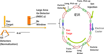
Figure 67. Schematic of NEEC experimental configuration using a gas target and down-stream NaI and Ge-detectors [269].
Download figure:
Standard image High-resolution imageThe gas target will provide a high target density of up to 1014 H2 cm−2. However, it will also include the probability to excite the first low-lying nuclear excited state via CX. The probability for the direct CX to the first excited state is very small as compared to being fed via a cascade of γ-rays from higher-lying states. An estimate of the probability for the indirect CX excitation at 20 MeV/u238U beam on hydrogen can be done by scaling from a previous experimental work by McGowan [273, 274], which observed thick target CX of 238U and 232Th using an 18 MeV α-particle beam and a Ge(Li) detector.
The work by McGowan and Milner showed that the direct CX excitation rate into the first excited state was approximately 4 excitations/nano-Coulomb as compared to a cascade excitation rate of 1000/nano-Coulomb [273, 274]. If the adiabaticity of the collision scales as e−2πη with η = α h v ΔE sin (θ/2), then the scaled cross section is less than 0.1 mb for 20 MeV protons incident on a 238U target. By assuming 5 × 10¹³ target atoms cm−2 and a repetition rate in the ring of 5 × 10⁵ Hz, this would result in about 0.4 excitations per 2 × 10⁷ particles in the ion train s−1. Since 99.6% of this CX is a result of cascades from high lying states, detection of these high-energy γ-rays can be used as a normalization for CX to the first excited state. These higher-lying states will decay promptly and the corresponding gammas will not contribute to the count rate on the detectors 3.5 m downstream the target. The Compton profile of the H2 target ions will be Doppler broadened to about 800 eV and needs to be taken into account for computing the resonance width (10–20 eV) and the rate estimates accordingly. Due to the wide energy spread of the observed photons a stringent detector energy resolution is not required.
The rate of NEEC events for the gas target can be estimated from RNEEC = S Ne N1 f ![$[1/{({{{\rm{\Gamma }}}^{2}}_{{\rm{Compton}}}+{{{\rm{\Gamma }}}^{2}}_{{\rm{Beam}}}+{{{\rm{\Gamma }}}^{2}}_{{\rm{Atom}}})}^{0.5}]$](https://content.cld.iop.org/journals/0954-3899/45/3/033003/revision2/jpgaa8693ieqn11.gif) to be ∼105 d−1, where the resonance strength S = σ/ΓAtom is a reduced cross section per unit energy, Ne (5 × 1013 cm−2) is the electron areal density of the target, Ni (2 × 10⁷) is the number of ions per bunch, f (6 × 10⁵ s−1) is the frequency of the bunch, and the term in parentheses accounts for nuclear resonance energy mismatch due to the Compton profile, ΓComp (800 eV), energy spread of the 238U beam, Γbeam (0.33 eV), and the atomic resonance width of the captured electronic state ΓAtm_width (16.5 eV). Thus, a signal from gamma decay after NEEC is expected to be stronger than background due to gammas emitted after CX, ∼3.5 × 10⁴ events d−1.
to be ∼105 d−1, where the resonance strength S = σ/ΓAtom is a reduced cross section per unit energy, Ne (5 × 1013 cm−2) is the electron areal density of the target, Ni (2 × 10⁷) is the number of ions per bunch, f (6 × 10⁵ s−1) is the frequency of the bunch, and the term in parentheses accounts for nuclear resonance energy mismatch due to the Compton profile, ΓComp (800 eV), energy spread of the 238U beam, Γbeam (0.33 eV), and the atomic resonance width of the captured electronic state ΓAtm_width (16.5 eV). Thus, a signal from gamma decay after NEEC is expected to be stronger than background due to gammas emitted after CX, ∼3.5 × 10⁴ events d−1.
The number of detected gammas incident on a 5 cm diameter Ge detector located in a detector pocket ∼3.5 m downstream from the gas target and ∼1.5 cm from the beam is given by Nγ,Ge = RNEEC *ΩGe and is about 100 γ d−1, where ΩGe is the solid angle of the detector including the detector geometry relative to the beam and the number of decays within the detector viewing window assuming a lifetime of 100 ns.
4.3.7. Search for NEEC process with extracted ions from CRYRING
The NEEC process [268, 275] is an atomic collision process where an initially free-electron is captured resonantly into a bound atomic orbital accompanied by simultaneous excitation of the nucleus, see figure 66. This is the exact inverse of the decay of nuclear states by IC. In addition to the straightforward motivation to study this fundamental coupling between nucleus and electron shells, this process may play an essential role in population of exited nuclear levels in HEDP. The latter is essential for reliable calculation of nucleosynthesis in stars.
One of the main background sources in NEEC searches are events due to Coulomb excitation, which probability depends strongly on the particle energy. Therefore, it is proposed to use the unique feature of CRYRING to slow the ions to lowest energies well below 1 MeV/u [263]. Performing experiments with stored beams and internal targets at such low energies is not easy. Therefore, the present suggestion is based on a possibility to extract low energy beams from CRYRING. Since the beam does not need to be stored in the CRYRING for a long time, it is possible that energies in the order of a few 10 keV/u can be approached.
As a test candidate to search for NEEC, a long-lived isomeric state can be used. For instance, 129Sb has a 17.7 min (19/2−) isomeric state at 1851 keV. It is noted, that this isomer might happen to be not the best choice, but the experimental procedure will change very little if a different isomeric state is considered in a real experiment. In the chosen example, the next excited state is merely 10 keV above the isomeric state. If one succeeds to induce a NEEC transition from the isomer to this state, it can be identified by an intense (∼100%) 732 keV γ-transition, see figure 68.
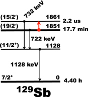
Figure 68. Level structure of 129Sb [229].
Download figure:
Standard image High-resolution imageA unique feature of the existing GSI accelerator family is that a beam of 129g,mSb can be produced in the FRS, purified from all contaminations and then be injected into the ESR as a pure mono-isotopic beam. The high kinetic energies allow for producing 129g,mSb as fully-ionized or few-electron ions. In addition, the ultra-high vacuum conditions allow for preserving this charge state for a long time. The ESR is a high-resolution mass spectrometer, which can be used for further purification of an isomeric beam of 129mSb.
The pure beam of 129mSb will be slowed down in the ESR to about 4 MeV/u and transported to the CRYRING, where it can further be slowed down to several tens of keV/u. At these energies, the beam of fully-ionized or few-electron 129mSb ions will be extracted and implanted onto a movable tape. The low kinetic energy has to be chosen to exclude Coulomb excitation of the isomer in the implantation material. The isomers will neutralize by capturing about 50 electrons. If the NEEC process occurs and populates the 1861 keV state, a 732 keV γ-line will be emitted, which can easily be measured by a conventional γ-detector. The neutralization will be accompanied by a huge background of <50 keV x-rays. A suitable absorber can be applied to prevent this background radiation from swamping the detector. The background from spontaneous decay of the isomer can be reduced by moving the tape after each implantation.
The number of possible candidates for the demonstration of NEEC is huge, and since all elements can be studied at GSI the best isomeric state will be selected for the pioneering experiment. Furthermore, if the pioneering experiments are successful, a systematic investigation of the NEEC as well as nuclear excitation in electron transition (NEET) [276, 277] processes and their dependence on the excitation-energy, transition multi-polarities, atomic charge state, atomic number etc can be envisaged.
The resonance properties of the electron shells can provide conditions for the reverse process of nuclear excitation by external electromagnetic fields in HEDPs. Such processes include the time-reversed discrete conversion, also known as NEET and the time-reversed continuum conversion, also known as NEEC. Experimental verification of the NEET and NEEC processes is scarce or not existing (NEEC).
Furthermore, even more exotic decay modes can be searched for, like, for instance Pauli forbidden bound internal conversion (PFBIC), which is proposed by Karpeshin et al [278]. The PFBIC, see figure 69, may take place in 197Au at ionizations with q > 69+. Li-, He-, H-like ions and bare gold nuclei have 3s electron vacancies and the BIC process turns into Pauli-allowed and all cascade K- and L- x-rays can experimentally be observed. Observation of the PFBIC process would serve for testing fundamental questions of the QED and Fermi statistics in physics [279, 280]. Experimentally one can address this process by utilizing heavy-ion accelerators. For instance, by using a high-Z target foil (e.g. 238U) where the excited states in 197Au that decay into its first excited state are produced via Coulomb excitation. The subsequent nuclear γ-decay would be observable down-stream together (if exists) with the two-photons from the PFBIC atomic transitions.

Figure 69. Two-photon IC between bound states in 197Au and Pauli blocking.
Download figure:
Standard image High-resolution image
If the PFBIC process exists, it may shorten lifetimes of nuclear states by orders of magnitude (20 orders in the case of 76 eV isomeric state in 238U), or may act to this effect as a natural resonator. This refers in particular to the discrete, or bound, or resonance conversion, also known as BIC (or TEEN (inverse to NEET)), when the transition strength is within a close vicinity of the atomic line. As a result, manipulating with a moderate-power laser, well tuned at the atomic resonance, or in HEDP environments one can attain the prompt decay of isomeric nuclear states, accompanied with the release of energy stored in them.
Nuclear excitations in HEDP are in general of great interest as fundamental physical processes. They affect the formation of heavy elements in stars, and their understanding is thus important for the development of models of galactic chemical evolution and astrophysical processes where they may take place, including the rapid (r-) and slow (s-) neutron capture processes. Moreover, nuclear excitation can be used for nuclear diagnostics of HEDP at facilities such as NIF, ELI, HIPER etc, by placing limits on time-integral temperature and pressure conditions in HEPs.
4.3.8. Experimental approaches focus on two schemes, one is based on ion beam foil type experiments and the other would utilize a HEDP environment produced in high-energy laser facilities such as the NIF
First results from NIF include the observation of both high-spin isomeric states in 196Au produced following 14 MeV neutron-induced reactions, and keV neutron energy capture products. The reactions are induced by neutrons from the highly compressed and heated DT fusion plasmas reacting with the Au in the NIF hohlraum indirect drive design. In this case, the Au hohlraum plasma is exposed to the neutrons and a comparison with future experiments, with Au loaded into the cryogenic DT target capsule, will allow to evaluate plasma effects as described above. In this kind of experiments the isomeric excitation is caused by neutrons which serve as a diagnostic for NPI occurring on the highly-excited compound nuclear states populated immediately following emission of evaporation neutrons. The effect of the plasma-induced NEEC/NEET reactions on Au nuclei in the capsule/hohlraum plasma would be to decrease the population of isomeric states produced by 14 MeV neutrons by shifting population away from the high-spin states that would feed the J = 12 isomer to the more abundant low-spin states that are more likely to feed the J = 2 ground state. However, these experiments suffer from limited solid debris collection efficiency would dramatically benefit from the improvements in this area.
At FAIR, the kinetic energies of stored ions in all considered heavy-ion storage rings are much higher than the thermal energies attained at the NIF. However, in NIF experiments, many complex plasma processes occur. By contrast, storage rings offer clean experimental conditions, which might isolate individual nuclear processes. One example is the NEEC process, which remains unobserved despite much research over several decades employing various methods. It should be emphasized though, that although the particles can be highly relativistic in the laboratory frame (E ∼ 400 A MeV in the ESR or E ∼ 5 A GeV in the HESR), the collisions with electrons in the center of mass system are tuned on meV levels. Thus, there are distinct advantages connected to the capability to precisely control the beam velocity, to the use of ultra-thin windowless targets and to having high resolving power. The high energy at HESR and the associated large Doppler shifts will enable laser spectroscopy on atomic transitions that are otherwise inaccessible. This capability suggests many exciting extensions, which will be developed in the future at the FAIR facilities. How it will be possible to employ the HESR, for example, for experiments directly relevant to the NIF will be a task for future research proposals.
Acknowledgments
We thank the operations and engineering staff at the National Ignition Facility for their dedicated professionalism which made the development and deployment of the various experimental diagnostics possible. Many valuable suggestions and critical comments by the larger external community during all phases of the experimental fielding are also gratefully acknowledged. We have benefited greatly from these collaborations. These many contributions highlight the importance of the NIF nuclear diagnostic data throughout the broader ICF research program. This work was performed under the auspices of Lawrence Livermore National Security, LLC, Contract No. DE-AC52-07NA27344 and by General Atomics under Contract DE-NA0001808.
We would also like to thank the following contributors: J Ayers, S Ayers, C Bailey, F Barbosa, B Beeman, L Bertolini, D Bower, C Brown, A Carpenter, D Casey, J Celeste, T Clancy, K Christensen, B Chow, J Church, P Datte, T Doeppner, R Hibbard, R Hoffmann, W Hsing, D Jedlovec, J Kimbrough, J Kroll, J Lerche, J Liebman, A Mackinnon, M McKernan, D Munro, A Nikroo, N Palmer, R Plummer, K Piston, A Riddle, G Ross, R Shelton, K Skulina, B Talison, A Throop, D Warwus, P Watts, M Yeoman and R Zacharias of Lawrence Livermore National Laboratory Livermore, California 94551, M Farrell and J Kilkenny of General Atomics, San Diego, California 92186, USA, G Ashabranner of Sandia National Laboratory, Albuquerque, New Mexico 87123,USA, V Glebov, J Knauer and T C Sangster of Laboratory for Laser Energetics, University of Rochester, Rochester, New York 14623,USA, N Kabadi, B Lahmann, R Petrasso and H Sio of Massachusetts Institute of Technology, Cambridge, Massachusetts 02139, USA, V Fatherly, A Hayes, R Leeper, J Oertel, P Volegov and C H Wilde of Los Alamos National Laboratory, Los Alamos, New Mexico 87545, USA, F F Karpeshin, S Yu Torilov of St. Petersburg State University, 198504 St. Petersburg, Russian Federation, T Stoehlker of Helmholtz Center for Heavy Ion Research, 64291 Darmstadt, Germany, and J Edwards, J Gostic, S Khan and Z Zeid.