

Abstract
Gallium oxide (Ga2O3) is a representative of ultra-wide bandgap semiconductors, with a band gap of about 4.9 eV. In addition to a large dielectric constant and excellent physical and chemical stability, Ga2O3 has a theoretical breakdown electric field strength of more than 8 MV cm−1, which is 27 times more than that of Si and about twice as large as that of SiC and GaN. It is guaranteed that Ga2O3 has irreplaceable applications in ultra-high-power (1–10 kW) electronic devices. Unfortunately, due to the difficulty of p-type doping of Ga2O3, the full Ga2O3-based bipolar devices face more difficulties, and the unipolar Ga2O3 power Schottky diodes are feasible, but substantial progress has been made in recent years. In this article, we review the advanced progress and important achievements of the state-of-the-art Ga2O3-based power Schottky barrier diodes, and provide staged guidance for the further development of Ga2O3 power devices. Multiple types of device architectures, including basic structure, edge terminal processing, field-plated, trench and heterojunction p–n structure, will be discussed in detail.
Export citation and abstract BibTeX RIS
1. Introduction
Power electronic devices will play an important role in future high-power, high-voltage applications, which can hardly be achieved by traditional silicon devices [1–4]. In particular, there will be very broad prospects for the development of electric automobiles, 5G, Internet of Things and in emerging application fields in the future. Si-based power devices, as the most mature power conversion chips, have reached their maximum capacity for power transmission, which means that they are unlikely to be the preferred choice for the next-generation higher-power devices due to increasing uneconomic R&D. As a result, wide-bandgap semiconductor-based power devices, mainly silicon carbide (SiC) and gallium nitride (GaN)-based devices have developed rapidly [5, 6]. As a representative of the third-generation semiconductors, SiC and GaN have very high breakdown voltage and low on-resistance that make them the ideal choices for high-power devices, making up for (even replacing) the commercial layout of Si-based power electronic devices [7–10].
Gallium oxide (Ga2O3) is a semiconductor material with a band gap of about 4.3–4.9 eV, varying in its five different phases (α, β, γ, δ and  ), which is larger than that of SiC (3.3 eV) and GaN (3.4 eV) [11–13]. The critical theoretical electric field strength of Ga2O3 is up to 8 MV cm−1, which is 27 times more than that of Si, three times greater than that of SiC, and twice as much as that of GaN [14–17]. It is guaranteed to have great potential for applications in ultra-high-voltage electronic devices. Baliga's figure of merit (BFOM), a key parameter to evaluate the suitability of power device fabrications, of Ga2O3 (>3000) is much larger than that of SiC and GaN by ten and four times, respectively, indicating that Ga2O3 is one of the most promising candidates for next-generation power electronics. Current edge-defined film-fed growth (EFG) technologies of β-Ga2O3 crystal have the advantage of low-cost, larger size and good crystal quality. High-quality epitaxial films of different thicknesses can be easily grown by metal-organic chemical vapor deposition (MOCVD), HVPE, molecular beam epitaxy (MBE), etc [18–26]. In addition, the substrate and epitaxy of Ga2O3 have easily tunable n-type doping ranging from semi-insulating to conductive, which boosts the development of Ga2O3 power electronics devices [27–31].
Over the past few decades, although GaN and SiC power devices have gradually replaced Si-based power devices in many applications, the industrial pain point of large-scale and high-cost GaN and SiC substrates is the most critical challenge for achieving high-performance power devices [32–34]. The high-quality, large-size and low-cost Ga2O3 substrates enable more promising opportunities for the semiconductor power device market [35, 36]. Compared to traditional p–n junction diodes, Schottky barrier diodes (SBDs) have lower turn-on voltages and faster recovery times, which results in them being commonly used as high-voltage and high-speed switching devices [37, 38]. In recent years, continuous investment has promoted significant progress for Ga2O3 SBDs with material advantage and mature n-type doping. However, the absence of p-type Ga2O3 directly hinders the design of bipolar devices [39]. Therefore, when one needs to solve the p-type problem, the unipolar Ga2O3 SBDs are most likely to be mass-produced first. Since Ga2O3-SBD simply fabricated using single-crystal β-Ga2O3 (010) substrates was reported in 2013 [40], Ga2O3 SBDs have been developing towards high breakdown voltage (VBR), low on-resistance (RON) and low production cost. In recent years, there has been a tremendous increase in research papers on Ga2O3 SBDs. By optimizing the epitaxial material, device structure and device fabrication process, there has been a continuous improvement in the performance of Ga2O3 SBDs. Ga2O3 SBDs have made a great breakthrough in high breakdown voltage, and some enterprises and research institutes have entered the stage of mass production. For example, Novel Crystal Technology Ltd has introduced an ampere-class 1200 V-Ga2O3 SBDs.
In this review, we summarize the current advances in technology and progress of Ga2O3-based SBDs. Specifically, a detailed introduction is carried out in various R&D teams who have reported mechanisms and methods, mainly including basic structure, field plate (FP), trench structure, ion implementation, thermal oxygen terminal and p-type heterojunction. The Ga2O3 substrate and epitaxy and material properties are discussed in section 2., Contacts between metal/Ga2O3 is introduced in section 3. Section 4 contains the current progress of Ga2O3 SBDs and heterojunction diodes (HJDs). Finally, the summary and prospects are covered in section 5.
2. Ga2O3 substrate and epitaxy
Ga2O3 is a transparent ultra-wide-bandgap oxide semiconductor material, which contains multiple-phase structures, all of which can be converted to β phase under certain conditions [12, 41–43]. Ga2O3 is the preferred semiconductor material for manufacturing high-temperature, high-frequency, high-power microelectronic devices and solar-blind UV photodetectors. In addition, compared to diamond, which is limited by its large size and high-quality single-crystal growth technology, Ga2O3 single crystal can be grown by economical and efficient melt preparation technologies, with high speed, low cost and high yield. Table 1 summarizes the relevant parameters of several common semiconductors, which demonstrates many material advantages of Ga2O3, such as wide band gap, high theoretical breakdown field strength (8 MV cm−1) and large BFOM. These advantages make it an ideal material for power electronics, such as high-voltage rectifiers and enhancement-mode metal-oxide field-effect transistors. At present, the majority of the substrates used in Ga2O3 SBD, as reported in the literature, were purchased or supplied by Japanese NCT. High-quality 6 inch Ga2O3 single crystal was successfully grown by EFG, and the industrialization of 4 inch Ga2O3 single crystal is available, which is currently the leading position in the world [13, 16], as shown in figure 1.

Figure 1. Status of EFG-grown bulk Ga2O3 wafer sizes. Reproduced from [16]. © IOP Publishing Ltd. CC BY 3.0.
Download figure:
Standard image High-resolution imageTable 1. Comparison of the performance parameters of the main semiconductor materials.
| Material | Si | GaAs | 4H-SiC | GaN | Diamond | Ga2O3 |
|---|---|---|---|---|---|---|
| Band gap (eV) | 1.1 | 1.43 | 3.25 | 3.4 | 5.5 | 4.85 |
| Electron mobility (cm2 V−1 s−1) | 1480 | 8400 | 1000 | 1250 | 2000 | 300 |
| Dielectric constant | 11.8 | 12.9 | 9.7 | 9 | 5.5 | 10 |
Baliga ( ) ) | 1 | 14.7 | 317 | 846 | 24 660 | 3214 |
| Breakdown field (MV cm–1) | 0.3 | 0.4 | 2.5 | 3.3 | 10 | 8 |
As the drift and channel layer, the high-quality epitaxial layer is important for Ga2O3 film power devices. At present, the majority of Ga2O3 power devices have always been reported achieving high-quality homoepitaxy or heteroepitaxy Ga2O3 film using hydride vapor phase epitaxy (HVPE) [44, 45], MBE [46, 47], MOCVD [48, 49], pulsed laser deposition [50, 51], physical vapor deposition (PVD) [52, 53] and mist CVD [44, 54]. HVPE and MBE are two of the most popular epitaxial growth tools and are also available commercially. Recently, HVPE has been successfully applied to thick epitaxial layers in most Ga2O3 SBD devices, and MBE has been widely used in the preparation of high-quality thin-drift layer films in Ga2O3 metal-oxide-semiconductor field effect transistor (MOSFET) devices.
HVPE is one of the most promising approaches in terms of deposition rate, layer quality and inexpensive facility. However, HVPE-grown films always have a rough surface, which requires a post-chemical mechanical polishing process to smooth it. MBE has very low surface roughness, but its slow growth rate limits its further development. As a mature epitaxial growth technique that has been widely used in GaAs and GaN epitaxial growth, MOCVD possesses great potential in commercial Ga2O3 epitaxial wafers in terms of fast deposition rate, smooth surface quality and mature growth process. The mist CVD technique is a safe, inexpensive and energy-saving method of film formation, without special components and a vacuum system. Mist-grown α-Ga2O3 films exhibit good crystal and surface roughness, which shows a high-performance α-Ga2O3 SBD device, with lower RON and greater VBR compared to SiC-SBD. The multi-epitaxial technology development provides a good guarantee for Ga2O3 thin-film devices.
3. Contact between metal and Ga2O3
The basic structure of Ga2O3 SBDs is composed of Ga2O3 material and Schottky contacts for the anode and Ohmic contacts for the cathode. Furthermore, the contact between metal and Ga2O3 is the main determinant of electron transport between interfaces, which further affects the performance of the device. The Schottky barrier is an intrinsic property that affects the charge transport at the metal–semiconductor interface, first proposed by Mott and called Mott's theory [38]. The Schottky barrier is generally the difference between the electron affinity energy of a metal and that of a semiconductor. The Schottky barrier height (SBH) is expressed as,

where Φm stands for the work function of the metal and χ is the electron affinity of the Ga2O3. The schematic energy band diagram of the formation of metal/Ga2O3 contact is shown in figure 2. When the metal and semiconductor contact, in order to make the Fermi energy level equal, the energy band of the Ga2O3 bends upwards and thus forms a large Schottky barrier at the Ga2O3/metal interface. The SBH is usually determined using experimental methods such as current–voltage (I–V) or capacitance–voltage (C–V). Experimental results show that the SBH of some semiconductors is only weakly dependent on the metal work function but depends mainly on the intrinsic properties of the semiconductor, as well as on the interface structure and interactions [55]. Therefore, the research on metal–semiconductor (M–S) contacts is essential, and the choice of metal electrode metal is also an important aspect of constructing Ga2O3 SBD devices. In addition, the high-conductivity compounds used as electrodes, such as Ga2O3 and TiN, form stable interfaces with Ga2O3 and exhibit excellent electron transfer performance, [56]. This section briefly introduces the progress and content related to the contact between Ga2O3 and metal materials.
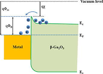
Figure 2. Schematic energy band diagrams of metal/Ga2O3 contact.
Download figure:
Standard image High-resolution image3.1. Ohmic contacts to Ga2O3
Usually, an excellent Ohmic contact has low or even no SBHs, and exhibits a linear current−voltage curve, which minimizes the energy consumption and also prevents thermal effects caused by contact resistance. This is especially important due to the intrinsic low thermal conductivity of Ga2O3. Hence, a superior Ga2O3 Ohmic contact is a prerequisite for achieving a high-performance device. Lee et al [57] described the interfacial reaction of Ti/Ga2O3 in detail and confirmed that Ti/Ga2O3 has a good Ohmic contact. Currently, most of the Ga2O3 device articles use Ti metal as the Ohmic contact [18, 37, 58–62]. Based on this, several effective methods have been used to further reduce the Ohmic contact resistance, such as doping [63], surface treatment [64], plasma treatment [65], etc. A recent report shows that Ga2O3 with heavy (n+) Si-doped (∼1.8 × 1020 cm−3) exhibits a record low Au/Ti/Ga2O3 (n+) contact resistance of 80 mΩ mm with specific contact resistivity of 8.3 × 10⁻⁷ Ω cm2 [63]. Jeong et al demonstrated Ohmic behavior with specific resistivity of 2.0 × 10⁻³ Ω cm2 and contact resistance of 0.8 Ω m by using CF4 plasma for surface treatment without any post-thermal annealing [64]. Massabuau et al reported the impact of annealing temperature on the Ohmic contact between Ti and α-Ga2O3 and demonstrated that 450 °C is optimal due to the fast diffusion channel provided at this temperature [65]. Therefore, Ti metal is the most promising and dominant Ohmic contact metal material for now.
3.2. Schottky contacts to Ga2O3
The Schottky diode is a majority-carrier-conducting device without the problem of minority carrier lifetime and reverse recovery, which is completely different to the reverse recovery of p–n junction diode caused by the recombination of electrons and holes. In addition, the SBH is lower than the p–n junction barrier. This advantage gives Schottky diodes a high switching frequency and a lower forward voltage.
In the early stage, most of the reports focused on the electronic properties of Ga2O3 SBD devices using metal−semiconductor Schottky contact structure without terminal design, surface passivation and other optimized processes. In this section, we briefly sum up the electronic behavior of Ga2O3 with various Schottky metals. There have been studies of Schottky contacts on different Ga2O3 orientation surfaces to analyze their characteristics, such as barrier height (SBH) and ideality factor (n). The characteristic performance of Schottky barriers is generally analyzed by I–V, CV curves. The details of different studies are summarized in table 2. The selection of a suitable Schottky metal electrode is a cornerstone for future studies of Ga2O3 Schottky SBD device performance. However, we are also aware that different interface characteristics and contact environments can affect the Schottky barrier, which requires specific analysis in each case. Various post-treatments are intended to reduce the interface states and to improve M−S contacts, attaining high performance with lower on-resistance (RON) and higher breakdown voltage (VBR).
Table 2. Summary of Schottky contacts on Ga2O3.
| Metal | Materials orientation (N cm−3) | SBH (eV) | n | References |
|---|---|---|---|---|
| Au | β-Ga2O3 (100) (1017–1018) | 1.2 (I–V) | 1.1 | [66] |
| Au | β-Ga2O3 (100) (6 × 10¹⁶–8 × 10¹⁷) | 1.23 (PES) | 1.02–1.09 | [67] |
| Au | α-Ga2O3 (0001) (2 × 10¹⁷–7 × 10¹⁷) | 1.7–2.0 (I–V) | 1.1 | [68] |
| Au | β-Ga2O3 (010) UID | 1.97 (C–V) | 1.09 | [69] |
| Ni | β-Ga2O3 (010) UID | 1.54 (C–V) | 1.04 | [69] |
| Ni | β-Ga2O3 (100) (6 × 10¹⁶–8 × 10¹⁷) | 0.97 (I–V) | — | [70] |
| 1.22 (C–V) | ||||
| Cu | β-Ga2O3 (−201) (5–8 × 10¹⁸) | 1.13 ± 0.1 (I–V) | 1.53 ± 0.2 | [61] |
| Cu | β-Ga2O3 (−201) (1.6 × 10¹⁸) | 0.8–0.95 (I–V) | 1.2–1.4 | [71] |
| Pt | β-Ga2O3 (010) UID | 1.59 (C–V) | 1.03 | [69] |
| Pt | β-Ga2O3 (010) (3 × 10¹⁶–5 × 10¹⁶) | 1.3–1.5 | ∼1 | [40] |
| Pt | β-Ga2O3 (001) (1 × 10¹⁶) | 1.09–1.15 | 1.03 ± 0.01 | [72] |
| Pt | β-Ga2O3 (100) (2.3 × 10¹⁴) | 1.3–1.39 (I–V) | 1.1 | [73] |
| W | β-Ga2O3 (−201) (5–8 × 10¹⁸) β-Ga2O3 (010) UID | 0.91 ± 0.09 (I–V) | 1.40 ± 0.4 | [61] |
| 1.05 ± 0.03 (I–V) | 2.68 ± 0.3 | |||
| W | β-Ga2O3 (−201) (2 × 10¹⁷) | 0.97 (I–V) | 1.04 | [74] |
| Ir | β-Ga2O3 (−201) (5–8 × 10¹⁸) β-Ga2O3 (010) UID | 1.29 ± 0.1 (I–V) | 1.45 ± 0.2 | [61] |
| 1.40 ± 0.08 (I–V) | 1.64 ± 0.2 | |||
| Mo | β-Ga2O3 (110) (2 × 10¹⁷) | 1.55 (I–V) | — | [75] |
| Pd | β-Ga2O3 (010) UID | 1.28 (C–V) | 1.05 | [69] |
4. Ga2O3 power SBD
Early reports on Ga2O3 SBD devices have already shown very good rectification characteristics using a simple device structure without additional edge termination or other special structures [76]. Subsequently, along with different device structures and process regulation of Ga2O3 SBDs to carry out research work, a considerable number of properties have shown substantial improvement. It is noted that most of the reported parameters of device performance are with regard to breakdown voltage (VBR), on-resistance (RON), forward current density (JF) and reverse leakage (IR). VBR and RON are the two most important parameters, which indicate the maximum voltage that the device can withstand in reverse and the resistance value in forward conduction, respectively. By continuously optimizing materials and device structures, we are able to achieve Ga2O3 SBD products that meet commercial high-voltage (low-energy) requirements. Hence, this section summarizes the development of Ga2O3 power SBD in various metal choices, device structures, Ga2O3 material modification, and device processes.
4.1. The basic structure Ga2O3 SBD
For Ga2O3-based SBD devices, the initial devices were prepared with only front-side Schottky contacts and backside Ohmic contacts on a single crystal to study the device performance [37, 73, 75, 77]. The schematic of the device is shown in figure 3(a). An initial report by Sasaki et al [40] proposed the use of a Pt circular electrode Schottky junction to fabricate Pt/Ga2O3 SBD on single-crystal β-Ga2O3 (010) substrates. This device, using simple device structures and processing techniques without terminal structures and other processes demonstrates ideal coefficients close to 1.0. The SBH between Pt and β-Ga2O3 was 1.3–1.5 eV with a high breakdown voltage of about 150 V. These results can be attributed to the high crystal quality of Ga2O3 substrates and show the great potential of Ga2O3 power devices for future applications. These were further developed by adding an epitaxial layer to those early SBD structures. Pearton et al [78] reported that β-Ga2O3 SBDs were fabricated in a vertical structure on Si-doped epitaxial layers (10 µm, n ≈ 4 × 1015 cm−3) on Sn-doped bulk Ga2O3 substrates, which includes Ni/Au front Schottky contacts and Ti/Au back Ohmic contacts. The schematic of the device is shown in figure 3(b). It shows the device with VBR values up to 1600 V (20 µm diameter contacts) and ∼250 V for rectifiers (0.53 mm diameter), and RON values were 25 and 1.6 mΩ cm2 respectively, leading to a BFOM for the latter of approximately 102.4 MW cm−2. The results show that Ga2O3 SBDs without additional structures and edge terminals exhibit high performance based on high-quality substrates and epitaxy. The latest work presents a high-performance Ni/(001) β-Ga2O3 regular SBD without edge termination with a high PFOM of 1.32 GW cm−2 and a maximum VBR of 1720 V by suppressing the formation of donor-like impurities accumulated on the surface [79]. Hence, Ga2O3 SBD has great potential for high-voltage applications.

Figure 3. Device schematic of vertical β-Ga2O3 SBD on a conducting β-Ga2O3 substrate and (b) the SBD on β-Ga2O3Ga2O3 epi-layer on a conducting β-Ga2O3 substrate.
Download figure:
Standard image High-resolution imageFurthermore, the development of α-Ga2O3 SBD has achieved great success. In 2015, FLOSFIA, INC. [68] used mist CVD epitaxy to grow 8 μm thick n+ epitaxial layer for Ohmic contact and n− epitaxial layer for Schottky contact on sapphire substrate and then removed the sapphire substrate to make α-Ga2O3 SBD, as shown in figure 4(a). The device showed a VBR of 270 V, n of 1.1 and a current on-off ratio of 106. The poor performance is caused by the current density limitation of the epitaxial layer. Afterwards, the conductivity of the α-Ga2O3 epitaxial layer was adjusted by controlling the doping of Sn to improve the performance of the SBD [80]. Two types of SBD were prepared, SBD 1 and SBD 2, of which SBD 1 with an n-epitaxial layer thickness of 430 nm exhibited low on-resistance (0.1 mΩ cm2) and VBR of 531 V; SBD 2 with an n- epitaxial layer thickness of 2580 nm exhibited a high breakdown voltage (855 V) and RON of 0.4 mΩ cm2, as shown in figures 4(c) and (d). Both SBDs have an n+ layer of 3–4 μm without edge termination, passivation or FP structure. The thermal resistance of the TO220-packaged α-Ga2O3 SBD device was found to be as small as 13.9 °C W−1. This value is comparable to that of a commercial SiC SBD device (12.5 °C W−1). This TO220-packaged α-Ga2O3 SBD also showed the fastest recovery compared to a commercial SiC SBD and a Si p−n junction diode [21]. This safe, low-cost and energy-efficient mist CVD epitaxial technology offers tremendous advantages for α-Ga2O3 power device applications. The comparison of electric performances for basic structure Ga2O3 SBDs are summarized in table 3.

Figure 4. (a) Fabrication process of an α-Ga2O3 SBD. (b) Forward current density versus applied voltage characteristics of α-Ga2O3 SBDs. (c) Reverse current density versus applied voltage characteristics of α-Ga2O3 SBD1. (d) Reverse current density versus applied voltage characteristics of α-Ga2O3 SBD2. Reproduced from [80]. © 2016 The Japan Society of Applied Physics. All rights reserved.
Download figure:
Standard image High-resolution imageTable 3. Comparison of electrical performances for basic-structure Ga2O3 SBDs.
| Device structure | Carrier concentration (cm−3) | VBR (V) | VON (V) | RON (mΩ cm2) | FOM (MW cm−2) | References |
|---|---|---|---|---|---|---|
| Pt/Ti/Au with UID substrate | 3 × 10¹⁶ (600 μm) | 150 (Φ100 µm) | 1.23 | 7.85 | 3.1 | [40] |
| Pt/Ti/Au with UID substrate | 2.3 × 10¹⁴ (∼600 μm) | >40 (Φ100 µm) | 1.07 | 80 | — | [73] |
| Au/Ti/Pt with substrate | 2 × 10¹⁷ (0.48 μm) | 200 (Φ150 µm) | 0.63 | 2.9 | — | [37] |
| Mo/Au with substrate | 2 × 10¹⁷ (15 μm) | 260 (Φ100 µm) | — | — | 3 | [75] |
| Ni/Au SBD | 2 × 10¹⁶ (15 μm) | 100 (0.1 × 0.3 cm2) | — | 23 | 0.435 | [81] |
| 3.6 × 10¹⁸ (650 μm) | 466 (40 × 40 µm2) | 0.59 | 368 | |||
| Pt/Ti/Au SBD | 2 × 10¹⁶ (7 μm) | 500 (Φ30 µm) | 1.1 | 1 | — | [72] |
| 2.5 × 10¹⁸ (—) | ||||||
| Ni/Au SBD | 2 × 10¹⁶ (10 μm) | 1016 (Φ105 µm) | 6 | 1.54 × 10⁻⁴ | [82] | |
| 3.6 × 10¹⁸ (650 μm) | ||||||
| Ni/Au SBD | 4 × 10¹⁵ (10 μm) | 1600 (Φ20 µm) | — | 1.6–25 | 102.4 | [78] |
| 3.6 × 10¹⁸ (650 μm) | ||||||
| Ni/Au SBD | ∼1.2 × 10¹⁶ (9 μm) | 1720 (Φ100 µm) | — | 2.25 | 1320 | [79] |
| 3.6 × 10¹⁸ (—) | ||||||
| Pt/Ti/Au SBD (α-Ga2O3) | 1 × 10¹⁷ (0.43 μm) | 532 (Φ30 µm) | — | 0.1 | — | [80] |
| 3 × 10¹⁹ (3∼4 μm) | ||||||
| 1 × 10¹⁷ (2.58 μm) | 855 (Φ30 µm) | — | 0.4 | — | ||
| 3 × 10¹⁹ (3∼4 μm) |
4.2. Ga2O3 SBD with edge terminal processing
While there has been tremendous development of Ga2O3 devices, there are still many ways to improve device performance. Simple processes offer advantages in terms of industrialization and device reliability. Therefore, we want the fabrication process of Ga2O3-SBD to be as simple as possible. Ion-implantation terminal edge-termination technology can create a high-resistance region, thus forming effective electron isolation around the anode edge region. This effectively relieves the electric field crowding effect by reducing the peak value, as shown in figure 5(a). Therefore, the reported method of implementing ion-implanted edge termination, is a well-proven and effective way to increase the device performance of Ga2O3-SBD. Zhou et al [83] reported that Mg-implanted edge-termination processing is a very simple but useful technique to improve the VBR of the vertical β-Ga2O3 SBD. Compared to the device without Mg-implanted edge-termination treatment, the breakdown voltage of β-Ga2O3 SBD is substantially increased from 500 to 1050 V. In addition, it was shown that a high power figure of merit (PFOM) of 0.47 GW cm−2 and low RON of 5.1 mΩ cm2 were realized at an epitaxial layer thickness of 10 µm with a diode radius of 90 µm. There is a slight increase in VBR when the anode radius is decreased and a VBR of 1.65 kV is demonstrated at R = 40 and 65 μm. To verify the effect of Mg-implanted edge termination on the device, technological computer-aided design (TCAD) simulations were carried out on the device with and without edge termination. The results showed the effectiveness of the implanted edge termination to mitigate the peak electric field at the anode edge and hence an enhanced breakdown voltage is expected. A similar approach is used to increase the breakdown voltage using an N-implanted guard ring [84]. The reverse leakage current is several orders of magnitude lower than the Mg-implanted edge-termination β-Ga2O3 SBD and the VBR by up to 860 V. In addition, the Ga2O3 SBD was fabricated by using argon-implantation edge-terminated technology to form the high-voltage resistance performance at the periphery of the anode contacts [85, 86]. The results indicate great promise of vertical β-Ga2O3 SBDs for high-voltage and fast switching applications. The most recent reports on ion implantation to achieve high-performance vertical β-Ga2O3 SBD were based on a self-aligned beveled fluorine plasma treatment (BFPT) edge-termination structure [87]. Due to the strong electronegativity of fluorine ions, the introduction of numerous F negative charges will relieve the electric field pressure and therefore reduce reverse leakage and increase the breakdown voltage. The results indicate VBR up to 1050 V with a relatively low RON of 2.5 mΩ cm2, which is an excellent performance to date using a simple, effective and versatile edge-termination technique for self-aligned BFPT. This simple, easy-to-control edge-termination technique offers great advantages for fabricating high-quality, high-performance Ga2O3 SBD devices.
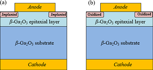
Figure 5. Device schematic of vertical β-Ga2O3 SBDs with (a) implanted edge termination, (b) thermally oxidized edge termination and (c) filled SiO2 layer edge termination.
Download figure:
Standard image High-resolution imageWang et al [88] reported a novel edge-termination process to achieve a high-performance β-Ga2O3 vertical SBD by using thermally oxidized termination. The schematic of the device structure is shown in figure 5(b). The high-temperature thermal oxidation treatment reduces the electron concentration in the anode edge region and effectively suppresses the peak electric field at the device edge. For oxidation-terminated SBD annealed at 400 °C, the VBR of β-Ga2O3 SBD increases from 380 to 940 V, but the RON only increases from 2.9 to 3.0 mΩ cm2. The device demonstrates a PFOM (VBR 2/RON) as high as 295 MW cm−2. The decrease in the electron concentration in the oxidized region can effectively reduce the peak electric field at the Schottky contact edge. The simulation results of the lateral electrostatic field indicate that the thermally oxidized termination shows a new way to improve the breakdown characteristics of β-Ga2O3 SBD. Recently, Hao Yue's team reported a new terminal structure approach by incorporating the etched and filled SiO2 layer process to obtain a record-high breakdown voltage of 6 kV and a low RON of 3.4 mΩ cm2 for β-Ga2O3 SBD [89]. The device schematic is shown in figure 6. This simple and effective terminal structure allows Ga2O3 SBDs to be pushed to higher-voltage applications in power electronics.
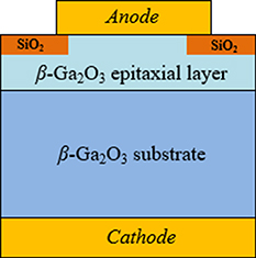
Figure 6. Device schematic of vertical β-Ga2O3 SBDs with filled SiO2 layer edge termination.
Download figure:
Standard image High-resolution imageIn general, the edge-termination technique is the simplest, most effective and most versatile to achieve a termination cutoff at the edge of the device, which effectively increases VBR and improves electrical properties at the electrode, by reducing the edge electron concentration and alleviating peak electric field. Therefore, this is greatly advantageous in preparing high-quality Ga2O3 SBD devices by using the simplest process possible. The comparison of electrical performances for β-Ga2O3 SBDs with edge termination (ET) are summarized in table 4.
Table 4. Comparison of electrical performances for β-Ga2O3 SBDs with edge termination (ET).
| Device structure | Carrier concentration (cm−3) | VBR (V) | VON (V) | RON (mΩ cm2) | FOM (MW cm−2) | References |
|---|---|---|---|---|---|---|
| Ni/Au SBD with Mg-implanted ET | 1.5 × 10¹⁶ (10 μm) | 1550 (Φ90 µm) | 0.82 | 5.1 | 470 | [83] |
| 1.7 × 10¹⁹ (650 μm) | ||||||
| Pt/Ni/Au SBD with N-implanted ET | 1∼1.2 × 10¹⁶ (7.8 μm) | 860 (∼Φ200 µm) | 1.5 | 4.9 | — | [84] |
| n+ (600 μm) | ||||||
| Ni/Au SBD with Ar-implanted ET | 1.3 × 10¹⁷ (10 μm) | 451 (—) | 1.5 | 3.3 | 61.6 | [85] |
| n+ (600 μm) | ||||||
| Pt/Ti/Au SBD with Ar-implanted ET | 4 × 10¹⁶ (8 μm) | 391 (Φ100 µm) | 1 | 4 | — | [86] |
| 2.6 × 10¹⁸ (640 μm) | ||||||
| Ni/Au/Ni SBD with beveled F-implanted ET | 3 × 10¹⁶ (8 μm) | 1050 (Φ100 µm) | 0.7 | 2.5 | — | [87] |
| 1.6 × 10¹⁹ (650 μm) | ||||||
| Ni/Au SBD with thermally- oxidized termination | 3 × 10¹⁶ (6 μm) | 940 (Φ150 µm) | — | 3 | 295 | [88] |
| 1.6 × 10¹⁹ (650 μm) | ||||||
| Ni/Au SBD with He-implanted ET | 1.6 × 10¹⁶ (10 μm) | 1000 (Φ65 µm) | 0.73 | 4.8 | 210 | [90] |
| 1.7 × 10¹⁹ (650 μm) | ||||||
| Ni/Au SBD with Mg-implanted ET | 1.6 × 10¹⁶ (10 μm) | 1500 (Φ65 µm) | 0.82 | 5.4 | 420 | [90] |
| 1.7 × 10¹⁹ (650 μm) | ||||||
| Ni/Au SBD with filled SiO2 layer ET | 1.3 × 10¹⁶ (10 μm) | 6000 (Φ90 µm) | 1.45 | 3.4 | 10 600 | [89] |
| 3 × 10¹⁹ (500 μm) | ||||||
| Pt/Au SBD with Compound ET | n− (7 μm) n+ (650 μm) | 400 (Φ100 µm) | 0.7 | 4 | 40 | [91] |
4.3. Ga2O3 SBD with field-plated structure
The effect of long-term Ga2O3 SBD device performance reliability due to damage to the lattice by ion implantation has not yet been studied. We need to find more ways to address the premature breakdown voltage of Ga2O3 SBDs due to the presence of a peak electric field at the electrode edges. Field-plated (FP) technology is widely used in AlGaN/GaN HEMTs, SiC, GaN and other power devices to improve the reverse breakdown voltage and electron distribution characteristics [92–97]. FP techniques have the advantage of a simpler and more controllable manufacturing process, and the fact that they avoid the increased leakage associated with ion implantation, ion implantation and thermal oxidation can create uncontrollable ion diffusion problems. The FP structure needs to be built on a dielectric layer, and the selection of a suitable dielectric layer will also determine device performance [62, 98]. The initial report on Ga2O3 field-plated SBDs (FP-SBDs) indicated that they were successfully fabricated on a Si-doped n− Ga2O3 drift layer grown by HVPE on a Sn-doped n+ Ga2O3 (001) substrate [99]. The LFP = 20 μm FP Schottky anode electrodes were fabricated by realignment to the SiO2 windows, as shown in figure 7(a). The results show that RON was estimated to be 5.1 mΩ cm2 in a high VBR of 1076 V, and the simulated maximum electric field below the anode foot edge was 5.1 MV cm−1, as shown in figure 7(b). This is much larger than the theoretical limits for SiC and GaN and comparable to the extracted breakdown field for lateral Ga2O3 MOSFETs [100].
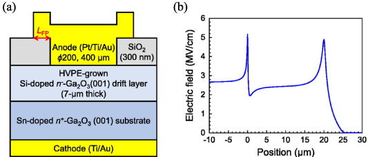
Figure 7. (a) Schematic cross-section of the Ga2O3 FP-SBD structure and (b) a maximum value of 5.1 MV cm−1 in the Ga2O3 drift layer at the anode foot edge. Reprinted from [99], with the permission of AIP Publishing.
Download figure:
Standard image High-resolution imageYang et al are conducting a series of studies on Ga2O3 FP technology and comparing the differences in FP SBD with different dielectric layers [62, 101]. They initially prepared a Ga2O3 FP SBD with an electrode area of 0.01 cm2 on a 10 µm thick, lightly doped drift layer (1.33 × 1016 cm−3) on heavily doped (3.6 × 1018 cm−3) substrates [102]. The device can achieve a forward current of 1 A and a reverse breakdown voltage of 650 V with a power density FOM above 20 MV cm−2, which is well within the parameters of a power rectifier. Later, a new Ga2O3 FP SBD was prepared in A 20 μm thick, lightly doped (n = 2.1 × 1015 cm−3) epitaxial layer on a conduction (n = 3.6 × 1018 cm−3) substrate with a 150 μm diameter device (area = 1.77 × 10⁻⁴ cm−2) [103]. The corresponding devices have further improved performance with breakdown voltages of up to 2300 V, as shown in figure 8. The on-state resistance (RON) for these devices was 0.25 Ω cm2, leading to an FOM (VBR 2/RON) of 21.2 MW cm−2 and can be adjusted to a voltage range of 1400–2300 V by changing the electrode size. In addition, a recovery time test with the device in the circuit showed a recovery time of only 20 ns from +2 to −2 V. In the future, the main focus will be on reducing the RON while continuing to increase the withstand voltage. To verify the application of the device in the circuit, the team prepared a switching circuit for high breakdown voltage Ga2O3 vertical Schottky rectifiers [104]. Based on this Ga2O3 FP SBD design, it can operate at switchable voltages of up to 900 V. Furthermore, a high-performance output current of 33.2 A and a PFOM (VBR 2/RON) of 4.8 MW cm−1 were achieved through the array structure consisting of 21 Ga2O3 FP rectifiers [60]. These results are another milestone for Ga2O3 towards its path for promising high-power electronic device applications since rectifiers are needed in inverter modules for power conversion systems.
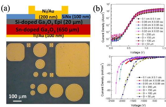
Figure 8. (a) Schematic of a vertical geometry Ni/Au Schottky rectifier with field-plate structure (top) and a top-view optical microscope image of the device layouts (bottom) showing different device areas. (b) Forward and reverse current density-voltage characteristic of rectifiers of different size (top). Reproduced from [103]. © 2018 The Electrochemical Society ("ECS"). Published on behalf of ECS by IOP Publishing Limited.
Download figure:
Standard image High-resolution imagePreviously, beveled field-plate (BFP) Ga2O3 SBDs were also reported by Joshi et al [20] and Allen et al [105]. The latter reported better performance with the FP SBD, which consists of spin-on-glass and plasma-enhanced chemical vapor deposited SiO2, to fabricate a very small bevel angle (∼1°) in the mesa and FPs. The BFP SBD greatly promotes the electric field distribution at device edges, which results in a VBR of 1100 V, a peak electric field of 3.5 MV cm−1,and a BFOM of 0.6 GW cm−2. Xia et al [106] also investigated the performance of FP Ga2O3 SBDs at different temperatures, with reverse VBR of 750 V at up to 600 K, 950 V at 500 K, and 1460 V at 400 K. Promising results of good protection against pressure and high-temperature operation were achieved. However, the FP-SBD device with the highest reverse breakdown voltage reported so far is a lateral structured device [107]. A high-performance lateral FP β-Ga2O3 SBD on a sapphire substrate with reverse VBR of more than 3 kV and a low DC RON of 24.3 mΩ cm2 at an anode-cathode spacing (LAC) of 24 μm is achieved. Overall, the external FP structure further improves the device's reverse breakdown voltage and exhibits a higher PFOM than the edge-termination structure.
In brief, FP structure techniques have been widely used in the fabrication of Ga2O3 power devices due to their relatively simple preparation process as well as the introduced external defects that cause increased reverse leakage. In order to implement the advantages of this FPe technology, more suitable high-dielectric materials are needed. In this way, FPs effectively reduce the peak value of the electric field at the edges of the channel. This will achieve a high breakdown voltage in Ga2O3 power devices. The comparison of electric performances for β-Ga2O3 SBDs with field-plated (FP) structure are summarized in table 5.
Table 5. Comparison of electrical performances for β-Ga2O3 SBDs with field-plated (FP) structure.
| Device structure | Carrier concentration (cm−3) | VBR (V) | VON (V) | RON (mΩ cm2) | FOM (MW cm−2) | References |
|---|---|---|---|---|---|---|
| Pt/Au/Ni SBD with beveled FP | 2.5 × 10¹⁷ (2 μm) | 190 (—) | — | 0.023 | — | [20] |
| 3.6 × 10¹⁸ (650 μm) | ||||||
| Ni/Au SBD with FP | 4.36 × 10¹⁵ (8 μm) | 650 (0.1 × 0.1 cm2) | — | 0.518 | 26.5 | [102] |
| 3.6 × 10¹⁸ (650 μm) | ||||||
| Ni/Au SBD with FP | 1.33 × 10¹⁶ (10 μm) | 760 (1.2 × 1.2 mm2) | — | 22 | 26 | [101] |
| 3.6 × 10¹⁸ (650 μm) | ||||||
| Ni/Au SBD with FP | 1.62 × 10¹⁶ (20 μm) | 240 (1 × 1 mm2) | 2.9 | 12 | 4.8 | [60] |
| 3.6 × 10¹⁸ (650 μm) | ||||||
| Ni/Au SBD with FP | 2.1 × 10¹⁵ (20 μm) | 2300 (Φ150 µm) | — | 0.25 | 21.2 | [103] |
| 3.6 × 10¹⁸ (650 μm) | ||||||
| Ni/Au SBD with small-angle beveled FP | 3–3.5 × 10¹⁵ (10 μm) | 1100 (Φ200 µm) | — | 2 | 600 | [105] |
| 2 × 10¹⁸ (400 μm) | ||||||
| Ni/Au SBD with FP (600 K) | 1.6 × 10¹⁶ (30 μm) | 750 (40 × 40 µm2) | 41 | 13.9 | [106] | |
| n+ (650 μm) | ||||||
| Ni/Au lateral film SBD with FP | 2.9 × 10¹⁷ (600 nm) | 2250 (LAC = 16 µm) | 10.2 | 500 | [107] | |
| Pt/Ti/Au SBD with FP | 1.8 × 10¹⁶ (10 μm) | 1076 (Φ200 µm) | 1.32 | 5.1 | 223 | [99] |
| n+ (650 μm) | ||||||
| Pt/Ti/Au SBD with FP and guard ring | 1 ∼ 1.2 × 10¹⁶ (7.8 μm) | 1430 (Φ200 µm) | 1.6 | 4.7 | — | [84] |
| n+ (600 μm) | ||||||
| Ni/Au SBD with high-k oxide FP | 9 × 10¹⁶ (1.7 μm) | 687 (Φ50 µm) | — | 0.32 | 1470 | [98] |
| conducting (—) | ||||||
| Ni/Au SBD with beveled high-k oxide FP | 3 × 10¹⁶ (8 μm) | 3108 (Φ20 µm) | — | 3.29 | 2940 | [108] |
| 2 × 10¹⁸ (2 μm) |
4.4. Ga2O3 SBD with trench structure
For conventional SBDs, the maximum electric field is located at the Schottky contact with surface higher reverse leakage current density at reverse bias, which means that limiting the electric field near the Schottky contact surface is necessary [109]. At present, various techniques, such as edge termination and FP structure, have been utilized to increase the VBR of Ga2O3 SBDs by slowing down the peak electric field at the edge of the electrode. However, a large reverse leakage current is present, under a large reverse electric field, at the Schottky metal–semiconductor interface with a single junction barrier [110]. To alleviate the leakage constraint and the distribution of the maximum field strength from the Schottky contact surface to the inside of the device body, many power devices use junction-barrier-Schottky (JBS) structures with p–n junctions to reduce the electric field near the Schottky contact interface due to the charge-coupling effect [111]. However, since the problem of Ga2O3 p-type technology has not been resolved, the Ga2O3 SBD will not be able to adopt the JBS structure either. Trench MOS structure of the SBD will be a good choice, and the MOS junction on the sidewall will replace the p–n junction in the JBS [112–114]. Here, the introduction of a metal-insulator-semiconductor (MOS/MIS) junction barrier structure not only increases the VBR with trench termination, but also effectively reduces leakage with reduced surface electric field (RESURF) techniques.
Sasaki et al [115] first reported the Ga2O3-Trench-MOS SBD. The SBD was fabricated on a 7 μm (001) epitaxial layer (n = 6 × 1016 cm−3) grown by halide vapor phase epitaxy (HVPE) on a single-crystal Ga2O3 substrate. Compared to the normal SBDs (RON = 2.3 mΩ cm2), the RON (2.9 mΩ cm2) is slightly higher, probably due to the reduced current path in the trench-MOS structure. The trench-MOS SBD has a leakage current several orders of magnitude smaller than the normal SBD, indicating that the trench MOS structure can effectively reduce the reverse leakage current. The device was tested for recovery characteristics by the double-pulse method [116]. It was confirmed that the trench MOS-Ga2O3-SBDs exhibit high speed and low loss recovery characteristics.
Many processing conditions affect the performance of the device, such as the appropriate thickness of the epitaxial layer, doping concentration, fin width, trench width, etc, which determine its final performance. In 2018, at the 76th Device Research Conference, it was reported that a trench-MIS device on 10 µm Si-doped n-Ga2O3 epitaxial layer grown on f 620 µm (001) n-type substrate, exhibited VBR of 1.5 kV with a ∼104 times reduction in reverse leakage current compared to regular SBDs [117]. Increasing the doping concentration of the epitaxial layer results in an increase in the forward current and a decrease in VBR (1230 V) [118]. However, it maintains non-declining forward characteristics compared to regular SBD with trench structure, indicating that the trench structure has a significant effect in reducing the surface electric field and effective MOS junction barrier height. Figure 9(a) shows the schematic cross-section of the trench SBDs with fin widths of 2, 3 and 4 μm, and trench depth of 2 μm, where the trench region uses MIS (MOS)-junction structure. As shown in figure 9(b), the electric field near the top surface is effectively reduced by the trench-MIS structure, and the RESURF effect is more pronounced with a smaller fin width. The trench depth is further reduced to 1.5 μm, and after dry etching in BCl3/Ar, the trench is then wet treated to remove the dry etch-induced damage and round the trench corners, resulting in devices with breakdown voltages of up to 2440 V and leakage current densities below 1 μA cm−2 [119].

Figure 9. (a) Schematic cross-section of the β-Ga2O3 trench SBD with fin widths of 2, 3 and 4 μm, and trench depth of 2 μm. (b) Simulated electric field profile at a reverse bias of 1200 V along vertically cut lines at the center of the fins [see the dashed line in (a)]. Electric field profile in a regular SBD is shown by the dotted line for comparison. Reprinted from [118], with the permission of AIP Publishing.
Download figure:
Standard image High-resolution imageTo further improve the reverse breakdown voltage of Ga2O3 SBDs, Huang et al [120] used TCAD simulations for optimization to investigate the effect of structural parameters on VBR and FOM based on the electric field distribution and edge effects at the bottom of the trench. As shown in figure 10, an optimized parameter of W = 4 μm and R = 1.2 μm, a maximum VBR of over 3 kV and a FOM of 2 GW cm−2 are predicted. As the structural patterns of Ga2O3 SBDs develop, and the breakdown mechanism is better understood, experiments are considered to adopt some composite structures to further improve the performance of the devices. An FP-trench SBD was fabricated with a double dielectric layer, and the trench structure was adapted with a fin width of 1 µm and a fin height of 1.1 µm [121]. From a simulation analysis of the FP-trench structure with a surface, it is shown that the FP largely eliminates the peak electric field at the anode edge and moves the peak electric field location to the outer edge of the FP. Compared to previous reports (VBR = 2400 V), this further increases the VBR of the SBD to 2.48 kV and achieves a FOM value of 0.78 GW cm−2 by pulse testing. By further optimizing the previous device, both the fin and the trench width are designed to be 1 µm, together with the edge FP structure [122]. The device exhibits a high VBR of 2.89 kV with a record high BFOM value of 0.80 (0.95) GW cm−2, among all Ga2O3 power devices reported so far. In general, the trench-MOS barrier structure effectively reduces the electric field in the plane, resulting in a much lower reverse leakage and a higher breakdown voltage, which compensates for the material limitations that make it difficult to implement the p-type. Next, with a suitable edge-termination structure, it is believed that the performance of the device can be further improved.
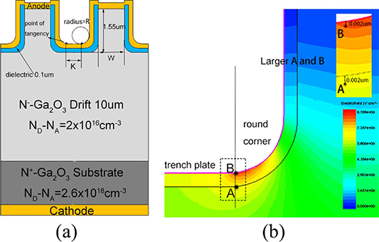
Figure 10. (a) Schematic of the SBD structure. (b) Electric field distribution and field strength gradient with a reverse bias for the Ga2O3 drift region E(A) and dielectric layer E(B). Reproduced from [120]. © IOP Publishing Ltd. CC BY 3.0.
Download figure:
Standard image High-resolution imageObviously, the trench-MOS structure of Ga2O3 is the preferred mode in kilovolt-level SBD devices with the base material p-type unresolved. The RESURF effect in trench-MOS structure not only improves the reverse leakage very well, but also improves the breakdown voltage to a great extent. However, there are still some details that need to be further investigated to reach an optimal device performance, such as optimization of the trench structure, suitable high-k dielectric layers and other process treatments. Together with other end-processing and FP structures, Ga2O3 SBD will have a huge potential in power devices. The comparison of electric performances for β-Ga2O3 SBDs with trench are summarized in table 6.
Table 6. Comparison of electrical performances for β-Ga2O3 SBDs with trench structure.
| Device structure | Carrier concentration (cm−3) | VBR (V) | VON (V) | RON (mΩ cm2) | FOM (MW cm−2) | References |
|---|---|---|---|---|---|---|
| Cu/Au/Ni SBD with MOS trench | 6 × 10¹⁶ (7 μm) | 240 (Φ400 µm) | — | 2.9 | — | [115] |
| 2.5 × 10¹⁸ (350 μm) | ||||||
| Mo/Ni/Al SBD with MOS trench | 6 × 10¹⁶ (7 μm) | 300 (Φ300 µm) | 0.5 | 3.09 | — | [116] |
| 5 × 10¹⁸ (500 μm) | ||||||
| Ni/Pt SBD with MIS trench | ∼2 × 10¹⁶ (10 μm) | 1232 (Wfin = 2 µm) | — | 15 | — | [118] |
| 2.6 × 10¹⁸ (—) | ||||||
| Ni/Ti/Pt SBD with MIS trench | 2 × 10¹⁶ (10 μm) | 2440 (Wfin = 1 µm) | 1.25 | 11.3 | 390 | [119] |
| 5.9 × 10¹⁸ (—) | ||||||
| SBD with optimized trench corner radius | 2 × 10¹⁶ (10 μm) | 3400 (Wfin = 1 µm) | — | 6 | 1700 | [120] |
| 2.6 × 10¹⁸ (—) | ||||||
| Ni/Ti/Pt SBD with FP MOS trench | ∼1.47 × 10¹⁶ (8.9 μm) | 2330 (Wfin = 1 µm) | — | 7 | 780 | [121] |
| 6.8 × 10¹⁸ (—) | ||||||
| Ni/Ti/Pt SBD with FP MOS trench | ∼1.47 × 10¹⁶ (8.9 μm) | 2890 (Wfin = 1 µm) | — | 8.8 | 950 | [122] |
| 6.8 × 10¹⁸ (—) | ||||||
| Pt/Ti/Au SBD with trench staircase FP | 2 × 10¹⁶ (8.5 μm) | 1660 (Wfin = Φ200 µm) | 2.1 | 7.6 | — | [123] |
| 6.8 × 10¹⁸ (—) | ||||||
| Ni/Ti/Pt SBD with FP MOS Trench | ∼7 × 10¹⁵ (8.45 μm) | 2400 (Wfin = 1 µm) | 1.25 | 20 | — | [124] |
| 5.9 × 10¹⁸ (—) |
4.5. Other Ga2O3-based diodes (p–n HJDs)
Although the unipolar Ga2O3 SBD device has been significantly developed, the difficulty of p-type doping has limited the development of Ga2O3 p–n power diodes. Early reports use other p-type materials to construct Ga2O3 p–n HJDs to achieve Ga2O3 bipolar power devices [125–127]. At this point, the heterojunction p-Cu2O/Ga2O3 diode already exhibits a very high breakdown voltage of 1.49 kV and has a very high forward current of over 100 A cm−2 [127]. Considering that the narrow band gap of p-Cu2O limits its potential, the p-NiO/Ga2O3 diodes also exhibit a high breakdown field strength of 1059 V and have an ultra-low reverse leakage current of below 1 μA cm−2 [128]. Ye et al [129] constructed a double-layered NiO/Ga2O3 vertical p–n HJD with different hole concentrations, as shown in figure 11. The device exhibits a very low leakage current and has a high rectification ratio of over 1010 (at ±3 V) even when operated at a temperature of 400 K, indicating its excellent thermal stability and operation capability at high temperatures. The breakdown voltage has also greatly improved to 1.86 kV with RON of 10.6 mΩ cm2.
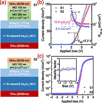
Figure 11. (a) Cross-section schematic of vertical NiO/β-Ga2O3 heterojunction diodes with two structural designs: (b) linear plots of J–V characteristics and extracted RON versus forward bias, where the turn-on voltage is obtained by fitting the linear segment and (c) semi-logarithmic plots of the J–V characteristics. Inset of (c) illustrates the extracted ideality factor. Reprinted from [129], with the permission of AIP Publishing.
Download figure:
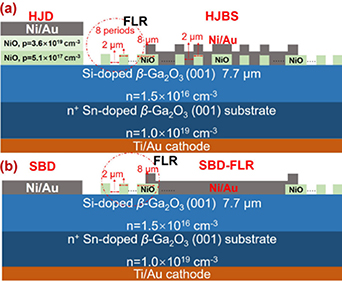
Standard image High-resolution imageThe devices have been tested on circuits up to 12 A/70 A and have achieved ultra-fast switching performance with a reverse recovery time of 11 ns at a surge-current of 45 A [130]. This gives the device significant potential for high-voltage, high-frequency applications. In addition, some studies have shown that the annealed NiO/Ga2O3 p–n junctions have a very low defect density and that the performance of the diode is significantly improved [131]. As the research progressed, the first vertical β-Ga2O3 JBS diode was prepared, using the thermally oxidized p-type NiO to compensate for the absence of the p-type β-Ga2O3 [132]. The JBS diode exhibits a high electrical performance with VBR of 1715 V and RON of 3.45 mΩ cm2, yielding a BFOM (VBR 2/RON) of 0.85 GW cm−2, which is the highest direct-current FOM value among all β-Ga2O3 diodes. Meanwhile, a large-size JBS diode with an area of 1 × 1 mm2 shows forward current IF and VBR of 5 A/700 V, which is also the best power factor (FOM = 64 MW cm−2) among all published results about large-area Ga2O3 diodes. Next, in order to carry out a comparative study, five types of P-NiO/Ga2O3 heterojunction power SBDs with different configurations were fabricated, which include the heterojunction p-NiO/Ga2O3 JBS uniform field-limited ring width/spacing of 2 μm (HJBS-2 μm), HJBS-3 μm, Ni/Ga2O3 SBD with a uniform field limiting rings (SBD-FLR), NiO/Ga2O3 p–n HJD and Ni/Ga2O3 bare SBD, as shown in figure 12. HJBS-2 μm achieves a maximum VBR of 1.89 kV and an RON of 7.7 mΩ cm2, yielding a high FOM of 0.46 GW cm−2. At the same time, the reverse leakage mechanism of HJBS is revealed to be Poole–Frenkel emission through localized trap states [133]. Recently, they have made a new breakthrough by reporting a novel composite terminal structure, including a p-type NiO junction termination extension and a small-angle BFP, which shows a much higher VBR of 2410 V and a low RON of 1.12 mΩ cm2, yielding a record-high power FOM value of 5.18 GW cm−2 [134]. In addition, p-GaN is also a good choice for constructing GaN/Ga2O3 p–n diodes with a low lattice mismatch of 2.6% [135], but there is little experimental research on GaN/Ga2O3 p–n power devices due to the fabrication limitations of GaN on Ga2O3. However, Nandi et al used TCAD simulations to propose a calibration model for the p-GaN/n-Ga2O3 junction barrier Schottky diode (JBSD) in Silvaco ATLAS. The JBSD provides better performance in terms of breakdown with a highest reverse breakdown voltage of 1890 V and a best switching time of 9.2 ns [136]. In fact, the heterojunction p–n also shows good performance and will be further developed when the p-type Ga2O3 problem is not resolved. The comparison of electric performances for β-Ga2O3 SBDs with p-n heterojunction structure are summarized in table 7.
Figure 12. Schematics of vertical NiO/Ga2O3 p–n HJD, Ni/Ga2O3 SBD and HJBS-2 μm diode terminated with p-NiO FLRs and Ni/Ga2O3 SBD terminated with p-NiO FLRs. Width of the first p-NiO FLR is 8 μm, those of the other p-NiO rings are 2 μm, and all the p-NiO ring spacings are 2 μm. Reprinted from [133], with the permission of AIP Publishing.
Download figure:
Standard image High-resolution image
Table 7. Comparison of electrical performances for β-Ga2O3 SBDs with p–n heterojunction structure.
| Device structure | Carrier concentration (cm−3) | VBR (V) | VON (V) | RON (mΩ cm2) | FOM (MW cm−2) | References |
|---|---|---|---|---|---|---|
| p-Cu2O/n-Ga2O3 diodes | >1018 (200 nm) | 1490 (Φ100 µm) | 1.7 | 8.2 | — | [127] |
| 4 × 10¹⁸ (10 μm) | ||||||
| p-NiO/n-Ga2O3 diodes | 1 × 10¹⁹ (200 nm) | 1059 (Φ200 µm) | 1.2 | 3.5 | — | [128] |
| 4 × 10¹⁶ (8 μm) | ||||||
| 2.6 × 10¹⁸ (—) | ||||||
| Double-layered p-NiO/n-Ga2O3 diodes | 3.6 × 10¹⁹ (100 nm) | 1860 (Φ200 µm) | 2.2 | 10.6 | 330 | [129] |
| 5.1 × 10¹⁷ (300 nm) | ||||||
| 1.5 × 10¹⁶ (7.7 μm) | ||||||
| n+(—) | ||||||
| Double-layered p-NiO/n-Ga2O3 diodes | 1.7 × 10¹⁹ (100 nm) | 1370 (1 mm2) | 1.73 | 2.6 | 720 | [130] |
| 5.1 × 10¹⁷ (300 nm) | ||||||
| 2 × 10¹⁶ (10 μm) | ||||||
| n+(—) | ||||||
| p-NiO/n-Ga2O3 diodes | 1 × 10¹⁹ (300 nm) | 1630 (Φ100 µm) | 1.65 | 4.1 | 650 | [131] |
| 2 × 10¹⁶ (10 μm) | ||||||
| 5 × 10¹⁸ (640 μm) | ||||||
| p-NiO/n-Ga2O3 JBS diodes | 1 × 10¹⁸ (60 nm) | 1715 (100 × 100 μm2) | 1 | 3.45 | 850 | [132] |
| 2 × 10¹⁶ (9 μm) | ||||||
| 5 × 10¹⁸ (—) | ||||||
| p-NiO/n-Ga2O3 JBS diodes with field-limiting rings | 1 × 10¹⁸ (280 nm) | 1890 (Φ200 µm) | 1.1 | 7.7 | 460 | [133] |
| 1.5 × 10¹⁶ (7.7 μm) | ||||||
| 1 × 10¹⁹ (—) | ||||||
| p-NiO/n-Ga2O3 diodes with composite termination | 1 × 10¹⁸ (80 nm) | 2410 (Φ60 µm) | 1.6 | 1.12 | 5180 | [134] |
| 1.8 × 10¹⁶ (6 μm) | ||||||
| 1 × 10¹⁹ (650 μm) |
4.6. Brief summary on SBDs
In this section, we introduce several different structures of Ga2O3 SBDs and detail a few of the current best-performing devices. At present, some of the most basic devices have breakdown voltages close to 1000 V and may play an important role in the low and medium power market. However, to further increase the device's withstand voltage, other structures must be used, such as FPs, trench-MOS, etc. In addition, high-quality materials are an important part of improving device performance. Therefore, the combination and optimization of all mentioned factors can lead to further improvement of the performance of Ga2O3 SBD. With the development of Ga2O3 devices, the following improved points should be focused on.
4.6.1. High-quality material base.
High-quality single crystal substrates and epitaxial films with controlled carrier concentration are the basic guarantee of outstanding and stable performance of Ga2O3 SBD. In particular, the high crystallinity and film uniformity exhibit a more consistent breakdown field strength, which prevents premature breakdown of the device. In addition, surface roughness and crystal defects are used as key factors to improve the properties of electrical conductivity and leakage of the device. Furthermore, a largesize wafer (>4 inches) is a basic requirement for industrialization, which can accelerate the industrialization of Ga2O3 devices. The solution of the p-type Ga2O3problem will open another window to Ga2O3-based power devices, which will enable further improvement. Therefore, the development of Ga2O3 materials is crucial as the cornerstone of device development.
4.6.2. Contact interface of metal/Ga2O3.
The contact between metal and Ga2O3 is the main determinant of electron transport between interfaces and further affects the performance of the device. A proper Schottky and Ohmic contact will be a key factor in influencing the forward and reverse electron transfer characteristics of the device. In addition, the I–V electronic characteristic curve can also be further improved by the contact interface, for example, high-k materials in trench-MOS structures can improve reverse leakage. Other suitable interfacial treatments will also be beneficial to improve the electron transfer characteristics, such as plasma treatment and interface annealing.
4.6.3. Device structure optimization.
The process of adding additional structure allows the Ga2O3 SBD to develop towards higher breakdown voltages, but the details of the structure still need to be further studied to achieve optimal performance. As mentioned above, the edge-termination structure and FP structure can effectively reduce the peak electric field at the verge of catastrophic breakdown, and effectively improve the breakdown characteristics. The trench-MOS barrier structure also has great advantages in reducing reverse leakage and increasing breakdown voltage. Consequently, a continuous structural optimization and combination will provide enhanced performance.
4.6.4. Device thermal management.
Due to the low thermal conductivity of Ga2O3 itself, Ga2O3 SBD suffers from a severe self-heating effect. The performance degradation will be greatly impacted under long-term high-temperature operation of Ga2O3-based devices. In particular, high-temperature operation can lead to severe current leakage and result in a decline in device reliability. A promising solution is to construct β-Ga2O3 heterojunctions integrated onto a high thermal conductivity substrate [137–140]. Xu et al reported the wafer-scale exfoliation of β-Ga2O3 thin films by an ion-cutting technique with H implantation and transfer onto 4H-SiC and Si substrates with high thermal conductivity. This avoids causing poor quality of the hetero-epitaxy-grown film due to the large lattice mismatch [141–145]. Compared to bulk Ga2O3 wafer, it demonstrated a fine performance improvement in leakage current and breakdown voltage and better thermal stability. However, most SBDs are vertical structures and it is clear that this method of transferring to a high-dielectric layer, high-conductivity substrate is not applicable. The fact is that there are already many ways to solve this problem with thermal management. For example, the double-sided packaging of Ga2O3 Schottky rectifiers exhibits a low thermal resistance of 0.5 K W−1 [146, 147]. We believe there will be more ways to solve the heat dissipation problem of Ga2O3 in the future.
4.6.5. Device reliability.
In order to achieve reliable applications of power Ga2O3 SBDs, it is important to investigate the reliability of the device over time and temperature. Some researchers report that temperature plays an important factor. A long-term high-temperature operation will lead to an increase in the current density and cause electrode metal degradation, and also induce an increase in the concentration of defects, which can seriously affect the normal operation of the device and even lead to device failure [148, 149]. The long-term reliability of Ga2O3 power diode operational capabilities in electronic power circuits will be an unavoidable challenge. Zhou et al [150] performed reliability verification of beveled-mesa NiO/β-Ga2O3 HJD after over one million times dynamic breakdown with a 1.2 kV peak overvoltage. The results showed that the reverse blocking characteristics caused no significant degradation and the beveled-mesa NiO/Ga2O3 p–n HJDs achieved a high conversion efficiency of 98.5% with 100 min stable operating capability into a 500 W power factor correction system circuit. Of course, there are few reports of reliability verifications like this, and further exploration of the reliability of Ga2O3-based power devices is needed to promote industrial applications.
5. Summary and prospects
In this review, we summarize recent advanced reports on Ga2O3-based SBDs. Due to the intrinsic superiority of the Ga2O3 material, it has great potential for the development of power devices and is expected to be one of the dominant materials used in the power electronics market, comparable to GaN and SiC. At present, Ga2O3 SBDs are in a rapidly developing stage, with breakdown voltage records that keep being broken. Thus, Ga2O3 SBDs have great prospects with the premise of ensuring the maturity of the material.
With the continuous development of semiconductor materials and the advent of the post-Moore era, wide-band semiconductors are destined to become the new choice in an era of rapid information technology development. Nevertheless, the properties of Ga2O3 and relevant microelectronics are still at early stages and need to be clarified. The development of Ga2O3 is still full of prospects and opportunities. Together with optimizing materials and structures to improve Ga2O3 SBD performance, the following points may be of interest.
- (a)To date, most of the research on Ga2O3 power devices has been on β phase. Other phase power devices will also be an interesting research direction in the future.
- (b)Compared to SiC, Ga2O3 SBD has already reached a relatively high level of withstand voltage. The next step is to continue to improve the withstand voltage and at the same time, we should increase the research on reducing the on-state resistance and verify the reliability of the device.
- (c)We still require a better thermal management method of Ga2O3 to solve the problem of poor thermal conductivity.
Acknowledgments
This work was funded by the National Natural Science Foundation of China (Grnat Nos. 61774019 and 61704153), the State Key Laboratory of Information Photonics and Optical Communications (Grant No. IPOC2018ZZ01) (Beijing University of Posts and Telecommunications) and the Fundamental Research Funds for the Central Universities, China.
Data availability statement
No new data were created or analyzed in this study.