

Abstract
The undoped BAlN electron-blocking layer (EBL) is investigated to replace the conventional AlGaN EBL in light-emitting diodes (LEDs). Numerical studies of the impact of variously doped EBLs on the output characteristics of LEDs demonstrate that the LED performance shows heavy dependence on the p-doping level in the case of the AlGaN EBL, while it shows less dependence on the p-doping level for the BAlN EBL. As a result, we propose an undoped BAlN EBL for LEDs to avoid the p-doping issues, which a major technical challenge in the AlGaN EBL. Without doping, the proposed BAlN EBL structure still possesses a superior capacity in blocking electrons and improving hole injection compared with the AlGaN EBL having high doping. Compared with the Al0.3Ga0.7N EBL with a doping concentration of 1 × 1020 cm−3, the undoped BAlN EBL LED still shows lower droop (only 5%), compatible internal quantum efficiency (2% enhancement), and optical output power (6% enhancement). This study provides a feasible route to addressing electron leakage and insufficient hole injection issues when designing ultraviolet LED structures.
Export citation and abstract BibTeX RIS
1. Introduction
AlGaN-based (III-N) ultraviolet (UV) light-emitting diodes (LEDs) have aroused widespread interests over the past few decades due to their various potential applications in purification, bio-detection, medical treatment, next-generation data storage, and lithography [1]. As a substitute for the conventional mercury lamp, UV LEDs are potentially energy efficient, long lifetime, compact, and environmentally friendly. However, the low efficiency and output optical power of the UV LEDs have hampered their adoption in various applications [2]. The currently developed LEDs operating in UV spectral regions still suffer from relatively low external quantum efficiency and substantial efficiency droop effect [3, 4]. The main reasons for the low efficiency have been identified to be the insufficient hole injection into the active region [5] and severe electron leakage out of the active region [6]. The commonly used electron-blocking layer (EBL) possesses several concerning issues. The electronic band edge profiles can be bent because of the polarization-induced electrostatic field, which may increase the hole injection barrier and further deteriorate the output performance of the LEDs [7]. Moreover, sufficient p-doping level AlGaN EBL is preferable for blocking electrons [8]. However, the activation energy of widely used p-dopants, e.g. Mg, dramatically rises with increasing Al mole fraction in the AlGaN layer, which makes the ionization of acceptors more challenging [9]. Furthermore, the diffusion of Mg atoms from the p-region to the active region is more severe in high-Al composition structures [10]. The induced Mg-related defects in multiple quantum wells (MQWs) will form nonradiative recombination centers, which are detrimental to the improvement of internal quantum efficiency (IQE) [11]. Besides, the Mg-induced defect will scatter electrons, leading to a low electron mobility [12].
To address the issues associated with the electron leakage, the hole injection, and the p-EBL, various solutions in the layer structures have been proposed. A superlattice was used as the EBL to suppress electron leakage and improve the overall performance of UV LEDs [13]. A quaternary AlInGaN EBL was also employed to reduce the polarization charge density in the heterostructure interface, which facilitates the reduction in band bending of the EBL [14]. Moreover, an EBL-free UV LED structure was proposed by utilizing graded-composition AlGaN quantum barriers (QBs) to realize better electron blocking and hole injection as opposed to the conventional structure with a p-EBL [15]. Researchers also designed the hole injection layers inserted between EBL and MQWs to effectively relieve the polarization-induced valence band bending [16]. Moreover, EBLs with graded composition [17], V-shaped structures [18], two-step tapered structures [19, 20] as well as polarization doped layers [21] show favorable potentials for UV LEDs. However, most of these methods could still suffer from the Mg diffusion issue.
Boron-containing III-N alloys, especially BAlN, are emerging wide-bandgap materials for optoelectronic and power devices. Recently, researchers have successfully grown BAlN/AlN and BAlN/AlGaN superlattices [22, 23]. The epitaxial growth of monocrystalline wurtzite BAlN structures with boron content as high as 11% and 14.4% have been demonstrated [24]. Liu et al have calculated the spontaneous polarization (SP) and piezoelectric (PZ) constants of BAlN using hexagonal reference structures [25]. The results also revealed that the heterointerface polarization can be modulated by adjusting the boron composition, which is beneficial for designing polarization-related electronic devices. Importantly for UV LEDs, the band alignment of BAlN/(Al)GaN heterostructure is extremely advantageous for electron confinement and hole injection. The valence and conduction band edges of B0.14Al0.86N are reportedly 0.2 eV lower and 2.1 eV higher, respectively, than those of GaN [26, 27]. Thus, the BAlN EBL is promising to supersede the conventional AlGaN EBL because of the possibility of suppressing electron leakage effectively without severely deteriorating hole injection.
In this study, motivated by the conduction and valence band offset properties, B0.14Al0.86N is employed as an alternative to Al0.3Ga0.7N for the EBL in UV LEDs. First, we systematically investigate the effect of p-doping in the Al0.3Ga0.7N EBLs with various doping levels on the output performance of LEDs. The result shows that the p-doping level of an EBL has a great influence on the effective barrier heights of the conduction and valence bands. The high p-doping level in the Al0.3Ga0.7N EBL decreases the valence band offset and increases the conduction band offset, facilitating hole injection and the confinement of electrons, respectively. Meanwhile, we further investigate the B0.14Al0.86N EBL, which shows the same tendency on effective band barrier heights as the Al0.3Ga0.7N EBL. However, the conduction and valence bands of B0.14Al0.86N EBL can maintain relatively high and low offsets, respectively, even with decreasing the Mg doping concentration. Finally, we propose an innovative undoped B0.14Al0.86N EBL for UV LED with superior performance to avert the challenging p-doping issue in high-Al composition layers.
2. Structures and parameters
Figure 1 presents a schematic cross-sectional structure of AlGaN LEDs including either the conventional Al0.3Ga0.7N EBL or the proposed B0.14Al0.86N EBL. The software we used for simulation is the Advanced Physical Models of Semiconductor Devices (APSYS) program [28]. The conventional structures are grown on a GaN/sapphire template, followed by a 3 μm-thick n-Al0.2Ga0.8N layer doped with silicon at a concentration of 5 × 1018 cm−3 (n-Al0.2Ga0.8N:Si, 3 μm, (Si) = 5 × 1018 cm−3). The active region is composed of five Al0.1Ga0.9N (3 nm each) quantum wells (QWs) (emitting at 344 nm) and six Al0.2Ga0.8N (14 nm each) QBs. Above the last QB is a 20 nm-thick p-Al0.3Ga0.7N EBL with various doping levels (Al0.3Ga0.7N:Mg, 20 nm, (Mg) = 0, 1 × 10¹⁵, 1 × 10¹⁶, 1 × 10¹⁷, 1 × 10¹⁸, 1 × 10¹⁹, 1 × 1020 cm−3). Then, a p-Al0.2Ga0.8N:Mg layer (100 nm, (Mg) = 2 × 1019 cm−3) and a p-GaN layer (10 nm, (Mg) = 1 × 1020 cm−3) are deposited in sequence. For the proposed structures, a B0.14Al0.86N EBL with the same thickness and changes in p-doping levels as the Al0.3Ga0.7N EBL is used. The other layers remain the same as the conventional structures. Both LED structures are designed to be 300 × 300 μm2 in size.
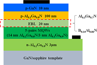
Figure 1. A schematic cross-sectional structure of UV LEDs with variously doped Al0.3Ga0.7N or B0.14Al0.86N EBLs.
Download figure:
Standard image High-resolution imageWe assume the conduction/valence band offset ratio of Al0.2Ga0.8N/Al0.1Ga0.9N MQWs is 0.7/0.3 [29]. The SP and PZ constants of B0.14Al0.86N and Alx Ga1−x N (x = 0, 0.1, 0.2, 0.3) are from [25, 30], which have proven to be accurate in calculating the polarization of III-N materials [31]. The lattice constant and elastic constants of BAlN alloy we adopted are from [25]. Besides, the affinity of B0.14Al0.86N is 0.9 eV, which has been demonstrated by Sun et al [26]. The bandgap of B0.14Al0.86N is set as 5.7 eV. Other parameters of BAlN for calculating band profiles could be found in [32]. The energy bandgap of Alx Ga1−x N alloys is estimated using equation (1), where b is a bowing constant and is chosen to be 0.94 [33], x is the Al content

The Auger recombination coefficient and Shockley–Read–Hall recombination lifetime are chosen as 1.0 × 10⁻³⁰cm−3 [34] and 50 ns, respectively. The radiative recombination rate is set to be 2 × 10⁻¹¹ cm3 s−1 [35]. The screening factor is set to 40%, which is a commonly used value for calculating the polarization-induced built-in interface charges [36]. The operating temperature and background loss are estimated to be 300 K [37] and 2000 m−1 [38], respectively. Although the p-B0.14Al0.86N has not been demonstrated in the experiment yet, the acceptor activation energy of B0.14Al0.86N should be similar to that of GaN because of their analogous valence band edge [26]. The effective mass of B0.14Al0.86N is from [32]. The activation energy of GaN or B0.14Al0.86N is supposed to be 170 meV [39], and the activation energy of Alx Ga1−x N is assumed to be 270 meV [40]. Generally accepted material parameters, including effective mass, electron and hole mobility values are applied to Alx Ga1−x N and GaN layers [41]. Other parameters can be found in table 1.
Table 1. Material parameters used in the simulation.
| Material parameters | GaN | AIN | B0.14Al0.86N |
|---|---|---|---|
| Lattice constant a (Å) | 3.189 | 3.112 | 3.027 |
| Lattice constant c (Å) | 5.185 | 4.981 | 4.798 |
| Bandgap (eV) | 3.4 | 6.1 | 5.7 |
| Crystal-field splitting (eV) | 0.010 | −0.169 | −0.169 |
| Spin–orbital splitting (eV) | 0.017 | 0.019 | 0.019 |
| Electron effective mass (c-axis) | 0.2 | 0.32 | 0.32 |
| Electron effective mass (transverse) | 0.2 | 0.30 | 0.29 |
| A1 | −7.21 | −3.86 | 2.72 |
| A2 | −0.44 | −0.25 | 0.77 |
| A3 | 6.68 | 3.58 | 0.40 |
| A4 | −3.46 | −1.32 | 0.77 |
| A5 | −3.40 | −1.47 | 1.57 |
| A6 | −4.90 | −1.64 | 0.29 |
| Affinity (eV) | 3.3 | 1.4 | 1.2 |
| Mg activation energy (meV) | 170 | 500 | 170 |
| Elastic constant C33 (GPa) | 398 | 373 | 480 |
| Elastic constant C13 (GPa) | 106 | 108 | 107 |
| PZ constant e31 (C m−2) | −0.3582 | −0.6691 | −0.6935 |
| PZ constant e33 (C m−2) | 0.6149 | 1.6422 | 1.7037 |
| Spontaneous polarization (C m−2) | 1.3389 | 1.3334 | 1.3834 |
| Piezoelectric polarization on GaN/sapphire template (C m−2) | 0 | −0.1229 | −0.2630 |
| Total polarization on GaN/sapphire template (C m−2) | 1.3389 | 1.2105 | 1.1204 |
3. Effects of p-doping level in EBLs
The p-doping level of EBL is a critical factor that deserves a considerable attention in designing high-performance LED structures. To evaluate the effects of EBLs at different doping levels on the performance of LEDs, we design the EBLs with a series of Mg doping concentrations (as described in part 2). Figure 2 shows the electronic band edge profiles for the LED structures with an Al0.3Ga0.7N EBL and a B0.14Al0.86N EBL with Mg doping concentrations from 1 × 10¹⁸, 1 × 10¹⁹ to 1 × 1020 cm−3 at an injection current of 90 mA. The EFn and EFp are the quasi-Fermi energy levels of electrons and holes, respectively. As the Mg doping concentration in the EBL increases, the effective barrier height of the conduction band (defined as Фe = Ec − EFn) can increase from 195 to 261 meV for Al0.3Ga0.7N EBL structures in figure 2(a). While for B0.14Al0.86N EBL structures, Фe can increase from 1.212 to 1.541 eV shown in figure 2(b). The significantly large Фe is because the lager conduction band offset between the Al0.2Ga0.4N QB and B0.14Al0.86N EBL. For both structures, the enhanced Фe suppresses the electron overflow out of the active region, indicating better capacities of confining electrons and reducing current leakage. As for the valence band, the effective barrier height (defined as Фh = EFp − Ev) decreases with increasing Mg doping concentration, suggesting an enhanced hole injection capability for both structures. The modification of the barrier heights in the EBL region can be explained by the fact that the quasi-Fermi energy level of holes will become closer to the valence band edge as the Mg doping concentration increases. The detailed information of Фe and Фh under different Mg doping concentrations are shown in table 2. It is noted that the large Фe and diminutive Фh of B0.14Al0.86N EBL are more favorable for the blocking of electrons and enhancing hole injection.

Figure 2. Electronic band edge profiles at an injection current of 90 mA for the LED structures with (a) Al0.3Ga0.7N EBL and (b) B0.14Al0.86N EBL at various Mg doping concentrations.
Download figure:
Standard image High-resolution imageTable 2. Barrier height of Al0.3Ga0.7N and B0.14Al0.86N EBL structures with various doping concentrations at 90 mA.
| Doping concentration of EBL | Al0.3Ga0.7N EBL structures | B0.14Al0.86N EBL structures | ||
|---|---|---|---|---|
| Фe (eV) | Фh (eV) | Фe (eV) | Фh (eV) | |
| 1 × 1018 cm−3 | 0.195 | 0.274 | 1.212 | 0.214 |
| 1 × 1019 cm−3 | 0.211 | 0.246 | 1.265 | 0.210 |
| 1 × 1020 cm−3 | 0.261 | 0.215 | 1.541 | 0.178 |
To verify the analysis shown in figure 2, we further study the electron and hole concentrations for both LED structures, as shown in figure 3. The electron leakage in both structures decreases with increasing Mg doping concentrations, as shown in figure 3(a). This phenomenon stems from the enlarged Фe as the increase of Mg doping concentration, which suppresses the electrons in the active region overflowing to the p-region. Comparing both LED structures, the LEDs with a B0.14Al0.86N EBL show more significantly reduced electron leakage, even when the doping concentration reduces to a lower level such as 1 × 1018 cm−3 due to the relatively high Фe. The electron and hole concentrations in the active region increase with the increase of p-doping levels for the LEDs with an Al0.3Ga0.7N EBL, resulting from the enlarged Фe and reduced Фh, respectively (shown in figures 3(b) and (c)). Because of the large and small barrier heights of the conduction and valence bands, the carrier concentrations in QWs show less difference for the LEDs with a B0.14Al0.86N EBL. Based on the aforementioned results, a higher p-doping level in the Al0.3Ga0.7N or B0.14Al0.86N EBL is preferable for the enhancement of hole injection and blocking electrons. However, the B0.14Al0.86N EBL structures with low p-doping level can still possess high performance while the performance of Al0.3Ga0.7N EBL structures with low p-doping level is seriously deteriorated.
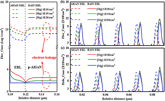
Figure 3. (a) Electron leakage in the p-Al0.2Ga0.8N layer, (b) electron concentration, and (c) hole concentration in QWs at an injection current of 90 mA for the LED structures with Al0.3Ga0.7N and B0.14Al0.86N EBLs at various Mg doping levels. For better observation, we shift electron and hole concentration of B0.14Al0.86N EBL structures in (b) and (c) to the right by 3 nm.
Download figure:
Standard image High-resolution imageFigure 4 shows the effect of the EBL with various doping levels on the IQE for both LED structures. The LEDs with an Al0.3Ga0.7N EBL exhibit an overall improvement in efficiency with increasing Mg doping concentration in the EBL. The increased IQE can be attributed to the enhanced hole injection and reduced electron leakage. Moreover, the efficiency droop ratio is reduced to 8% with the highest p-doping level for the LEDs with an Al0.3Ga0.7N EBL. The value of efficiency droop ratio is calculated using equation (2), where the IQEmax is the peak efficiency value and the IQE90 is the value of efficiency at 90 mA. For the LEDs with a B0.14Al0.86N EBL, the IQE shows a slight increase with higher Mg doping concentration, ascribed to the superior electron blocking capability and nearly consistent hole injection capability for all B0.14Al0.86N EBLs with different doping levels. The efficiency droop ratio of the LEDs with a B0.14Al0.86N EBL can still sustain at 5%, even when the doping concentration reduces to 1 × 1018 cm−3, at which doping level the efficiency droop is significant for the LED with an Al0.3Ga0.7N EBL. All of the peak efficiency value for the LEDs with B0.14Al0.86N EBLs can reach as high as 74%, higher than that for any one of the LEDs with an Al0.3Ga0.7N EBL. Apparently, the efficiency of the LEDs with B0.14Al0.86N EBLs is less sensitive to the doping concentration, while high Mg doping is imperative for AlGaN EBL to acquire the high-efficiency UV LED


Figure 4. Effect of p-doping level on IQE for Al0.3Ga0.7N and B0.14Al0.86N EBL LED structures at various Mg doping levels.
Download figure:
Standard image High-resolution imageFigure 5 shows the comparisons of current–voltage (I–V) characterization curves and output powers for both LED structures. The threshold voltage and resistance of these LED structures are presented in table 3. The threshold voltage and resistance decrease with increasing Mg doping for both LED structures, resulting from the increased carrier concentration. However, the degree of change is different. The threshold voltage and resistance of the LEDs with a B0.14Al0.86N EBL decrease substantially, whereas those of the LEDs with an Al0.3Ga0.7N EBL decrease slightly. The higher threshold voltage and resistance of the LEDs with a B0.14Al0.86N EBL are due to that the flow of charge carrier is hindered by the higher barrier height. The LED with an Al0.3Ga0.7N EBL having the highest p-doping level shows a remarkable improvement of output power when compared with that having the lowest doping level as shown in figure 5(b). Even with ten times higher Mg doping concentration than the lowest-doping-level Al0.3Ga0.7N EBL, the output power of Al0.3Ga0.7N EBL LEDs can still increase by 208%. As for the output power of the LEDs with a B0.14Al0.86N EBL having the highest p-doping level, a maximum value of 235 mW can be achieved. Nearly the same output powers for the LEDs with a B0.14Al0.86N EBL are attributed to the perfect electron blocking capability and slightly increased hole injection. As expected, the LEDs with a B0.14Al0.86N EBL having relatively low doping still show enlarged output power compared to the LEDs with an Al0.3Ga0.7N EBL having the highest doping level. It further confirms that the low-doping-level B0.14Al0.86N EBL is still vitally significant in designing high-performance UV LEDs. The wall-plug efficiency (WPE) of both LED structures is defined as the ratio of the total optical output power to the input electrical power. Although the LED with a B0.14Al0.86N EBL having the highest doping level shows a slight reduction in WPE as compared with the LEDs with an equally doped Al0.3Ga0.7N EBL, the LEDs with a B0.14Al0.86N having the lowest doping can still maintain the WPE at 51.2%.
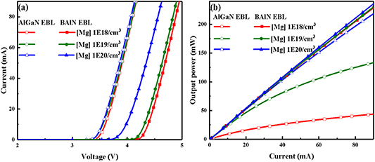
Figure 5. (a) I–V characterization curve of Al0.3Ga0.7N and B0.14Al0.86N EBL LEDs and (b) effect of p-doping level on output power for Al0.3Ga0.7N and B0.14Al0.86N EBL LEDs.
Download figure:
Standard image High-resolution imageTable 3. Characteristics of Al0.3Ga0.7N and B0.14Al0.86N EBL structures with various doping concentrations at 90 mA.
| LED structure | Al0.3Ga0.7N EBL LED | B0.14Al0.86N EBL LED | ||||
|---|---|---|---|---|---|---|
| Doping concentration | 1 × 1018 cm−3 | 1 × 1019 cm−3 | 1 × 1020 cm−3 | 1 × 1018 cm−3 | 1 × 1019 cm−3 | 1 × 1020 cm−3 |
| Thresholdvoltage | 3.56 V | 3.55 V | 3.52 V | 4.34 V | 4.29 V | 3.97 V |
| Resistance | 39.5 Ω | 39.4 Ω | 39.1 Ω | 48.2 Ω | 47.7 Ω | 44.1 Ω |
| WPE | 11.6% | 35.5% | 58.6% | 51.2% | 52.2% | 56.7% |
We conclude that the performance of the LEDs with an Al0.3Ga0.7N EBL shows heavy dependence on the p-doping level of EBL. As the doping concentration increases, the enhanced Фe holds back the transition of electrons to the p-region. Meanwhile, the reduced Фh promotes the hole injection to the active region. By comparing IQE and output power features for the LEDs with an Al0.3Ga0.7N EBL, we propose that the p-doping level of Al0.3Ga0.7N EBL is preferable to be improved for high-performance UV LEDs. As for the LEDs with a B0.14Al0.86N EBL, we show that the performance is less dependent on the p-doping level of EBL. With the decrease of doping concentration in B0.14Al0.86N EBL, the Фe shows a downward trend but maintains at a high level and Фh shows an upward trend but maintains at a low level, respectively. Meanwhile, the electron and hole concentrations, IQE, as well as output power show less difference in different doping levels in the B0.14Al0.86N EBL. We propose that the low-doping-level B0.14Al0.86N EBL can still make a difference for acquiring high-performance UV LEDs.
4. Undoped EBL LED
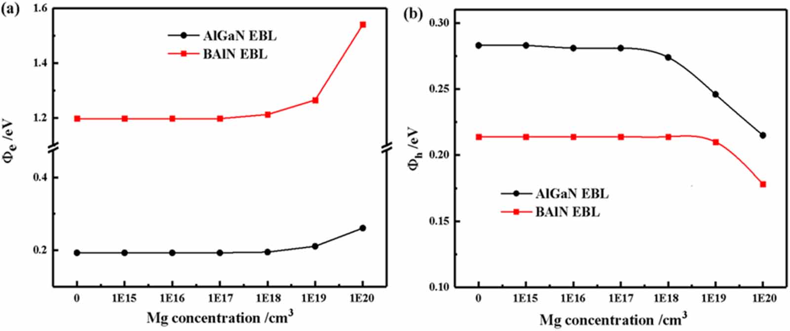
It is well known that the generally adopted AlGaN EBL in UV LEDs will deteriorate the hole injection and introduce nonradiative recombination centers in MQWs [8]. Motivated by the diminutive valence band edge and large conduction band edge, we design the B0.14Al0.86N EBL structures to avoid the p-doping issue. As discussed in part 3, the high p-doping level is not pre-requisite in designing EBL for LEDs after introducing the B0.14Al0.86N EBL. To thoroughly demonstrate the potential of the undoped B0.14Al0.86N EBL, we gather the effective barrier height of valence and conduction bands as a function of Mg doping concentration, as shown in figure 6. With low Mg doping concentration for both EBLs, the Фh and Фe barely decrease and increase with increasing doping concentration, respectively. Due to the relatively low activation energy of B0.14Al0.86N, the variations of Фe are more remarkable at the high p-doping level than that of Al0.3Ga0.7N. In contrast, the high-doping-level B0.14Al0.86N EBL is expected to provide a larger Фe and a smaller Фh. It is noteworthy that when the doping concentration reduces to zero, the Фe of B0.14Al0.86N EBL is 6.20 times that of Al0.3Ga0.7N EBL, while the Фh of B0.14Al0.86N EBL is 0.76 times that of Al0.3Ga0.7N EBL. Thus, the low-doping-level B0.14Al0.86N EBL still has great potential in reducing electron leakage and increasing hole injection, which is meaningful for the proposing of undoped B0.14Al0.86N EBL.

Figure 6. Effective barrier height of (a) conduction and (b) valence band for variously doped Al0.3Ga0.7N and B0.14Al0.86N EBL at 90 mA.
Download figure:
Standard image High-resolution imageTo prove the superiority of undoped B0.14Al0.86N EBL, we choose the undoped B0.14Al0.86N EBL structure to compare with the Al0.3Ga0.7N EBL structure with a high Mg doping concentration of 1 × 1020 cm−3, which is deemed to be over the doping limit in the experiment [42]. As figure 7 illustrates, the undoped B0.14Al0.86N EBL structure shows enhancements of the electron and hole concentrations in the QWs because it facilitates the blocking of electrons and hole transport into QWs simultaneously. Compared with the Al0.3Ga0.7N EBL structure, the increased electron concentration in the QWs of the undoped B0.14Al0.86N EBL structure is due to that the larger Фe can lead to a declined electron leakage. In the meantime, because the relatively low Фh promotes the hole injection, the hole concentration in QWs for undoped B0.14Al0.86N EBL structure shows an enhancement compared with the Al0.3Ga0.7N EBL structure. When it comes to the radiative recombination, an enhancement indicates that a higher intensity of emitting light can be achieved by the utilization of undoped B0.14Al0.86N EBL. Besides, for the undoped B0.14Al0.86N EBL structure, the electron and hole concentrations are the highest in the last QW, while the radiative recombination in the last QW is lowest. It can be attributed to the smallest overlapping of wave functions in the last QW, which is 32.99% as shown in table 4.
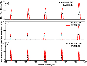
Figure 7. (a) Electron concentration, (b) hole concentration, and (c) radiative recombination rate in QWs for Al0.3Ga0.7N EBL structures and undoped B0.14Al0.86N EBL structures at 90 mA, respectively.
Download figure:
Standard image High-resolution imageTable 4. Overlapping of wave functions of the undoped B0.14Al0.86N EBL structure.
| QWs | 1st QW | 2nd QW | 3rd QW | 4th QW | 5th QW |
|---|---|---|---|---|---|
| Overlapping of wave functions | 41.49% | 41.35% | 41.36% | 41.38% | 32.99% |
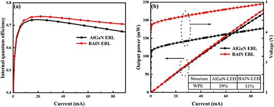
IQE is another vital parameter to evaluate the performance of the undoped LED. As shown in figure 8(a), the undoped B0.14Al0.86N EBL structure displays a slightly increased peak efficiency of 74% and reduced efficiency droop ratio at 90 mA compared with that of Al0.3Ga0.7N EBL structure. Figure 8(b) represents the output power, I–V curve, and WPE for both structures. A slight improvement of output power is achieved by employing undoped B0.14Al0.86N EBL to replace Al0.3Ga0.7N EBL. Both of the improved IQE and enhanced output power are ascribed to the subdued electron leakage and enhanced hole injection for the undoped B0.14Al0.86N EBL structure. The threshold voltage of the undoped EBL is 4.38 V, while that value of AlGaN EBL is 3.52 V. The calculated WPE of the undoped B0.14Al0.86N EBL structure is around 51%, which is slightly lower than the Al0.3Ga0.7N EBL structure of 59%. The slightly low WPE is attributed to the large forward voltage induced by the higher band barrier height of the B0.14Al0.86N EBL structure, and it will not lead to severe power dissipation.
Figure 8. (a) IQE, and (b) output power features, I–V curve, and WPE for Al0.3Ga0.7N and undoped B0.14Al0.86N EBL LEDs.
Download figure:
Standard image High-resolution image
In summary, we propose an undoped B0.14Al0.86N EBL structure to compare with the high-doping-level Al0.3Ga0.7N EBL structure. The results show that the undoped B0.14Al0.86N EBL structure still exhibits significant enhancements in blocking electrons and improving hole injection, because of the lager Фe and smaller Фh. As for the characterization curve, the B0.14Al0.86N EBL structure shows comparable IQE and mitigates efficiency droop as well as elevated output power density compared with the Al0.3Ga0.7N EBL structure. Moreover, the extremely challenging p-doping issue in the conventional AlGaN EBL can be alleviated by the employment of the undoped B0.14Al0.86N EBL. Furthermore, the absence of doping for the EBL would avoid the quality deterioration by heavy Mg doping as in the AlGaN EBL. In addition, after the introducing of an undoped B0.14Al0.86N EBL, the Mg diffusion issue, which is a well-known cause for lower radiative recombination rate, also can be relieved.
5. Conclusion
The influence of various doping concentration Al0.3Ga0.7N and B0.14Al0.86N EBLs on the output features of UV LEDs has been systematically investigated. We reveal that the high doping level in Al0.3Ga0.7N EBL is critical for the suppression of electron leakage and facilitates hole injection by elevated Фe and reduced Фh. As a result, for LEDs with an Al0.3Ga0.7N EBL with a doping concentration of 1 × 1019 cm−3, significant improvement in output power (208%) and enhanced IQE is achieved when compared with the LEDs with an Al0.3Ga0.7N EBL at a doping concentration of 1 × 1018 cm−3. When adopting a B0.14Al0.86N EBL instead of the Al0.3Ga0.7N EBL, the performance of UV LEDs shows less deterioration with the decrease of doping concentration due to the intrinsic large conduction band offset and pimping valence band offset at B0.14Al0.86N/Al0.2Ga0.8N heterointerface. The comparison between the proposed undoped B0.14Al0.86N EBL structure and the conventional highly doped Al0.3Ga0.7N EBL structure further demonstrates the potential of B0.14Al0.86N EBL in improving the performance of UV LEDs. Based on these results, we propose an undoped B0.14Al0.86N EBL structure, which is compatible with doping-free and high performance. By the employment of undoped B0.14Al0.86N EBL, the p-doping issue in the conventional Al0.3Ga0.7N EBL can be alleviated and therefore the epitaxy progress can be simplified. This work offered a novel sight to design high-performance UV LEDs without considering the high p-doping issue.
Acknowledgments
The KAUST authors would like to acknowledge the support of KAUST Baseline Fund BAS/1/1664-01-01, GCC Research Council Grant REP/1/3189-01-01, and Competitive Research Grants URF/1/3437-01-01 and URF/1/3771-01-01. The authors of Institute of Semiconductors would like to acknowledge the support of National Key R&D Program of China 2016YFB0400800, National Natural Sciences Foundation of China 61875187, 61527814, 61674147, and U1505253, Beijing Nova Program Z181100006218007, and Youth Innovation Promotion Association CAS 2017157.