
Abstract
Two-dimensional electromechanical metamaterials composed of thin plates with local piezoelectric resonators can display extreme vibration attenuation characteristics at desired frequencies. The typical bandgap analyses in the literature use the assumption of wave propagation in an infinite elastic structure and do not consider the modal characteristics of the structure. However, for practical implementation and design of finite-size electromechanical metamaterials, modal behaviour of the host structure and piezoelectric elements must be coupled with the dynamics of shunt circuits. To this end, we present a system-level modal analysis framework for finite-size thin plates with a segregated array of piezo-patches connected to resonant shunt circuits. The developed model takes into account the spatially discontinuous flexural rigidity of the metamaterial plate due to discrete placement of piezoelectric resonators on the substrate. Using the developed framework, we show that the electrical quality factor of resonators is critical for transitioning from broadband shunt damping to bandgap formation in piezoelectric plate metamaterials. This enables on-demand tailoring of effective dynamic stiffness of metamaterial plates for the targeted task. Lastly, for a fixed number of discrete resonators, we demonstrate the effect of physical gap size between resonators on the bandgap creation. Overall, the modelling frameworks in this study can be used for predicting the dynamics of piezoelectric plate-type metamaterials for applications in waveguiding, attenuation, filtering, and energy harvesting.
Export citation and abstract BibTeX RIS

Original content from this work may be used under the terms of the Creative Commons Attribution 3.0 license. Any further distribution of this work must maintain attribution to the author(s) and the title of the work, journal citation and DOI.
1. Introduction
Piezoelectric shunt damping techniques have been extensively studied over the past decades as an alternative to the conventional bulky mass-spring-damper systems for attenuating the vibrations of flexible structures. Piezoelectric patches can be directly integrated to vibrating host structures, without adding significant mass and volumetric occupancy, and convert the mechanical energy into the electrical energy which can be dissipated [1, 2] or stored [3–5] in various electrical circuit components. Forward [1] first demonstrated the shunt damping of an optical structure using one piezoelectric patch as a sensor and another one as an actuator driven by a negative feedback. Hagood and von Flotow [2] showed that a piezoelectric patch shunted to an inductive circuit forms an electrical resonance, acting as equivalent to a pure mechanical vibration damping system. Other research groups have used a network of multi-modal damping resonant shunt circuits [6–8] for broadband vibration control of flexible structures or implemented negative capacitance circuits [9–11]. Several others have proposed using an array of structurally integrated piezoelectric patches connected to electrical networks with the partial differential equations analogous to those of the host beam [12] and plate [13, 14] structures. In addition, non-linear switch-based circuits have been considered as effective semi-passive methods for shunt damping [15–17], although they add up extra electronic complexities.
Recently, piezoelectric shunt damping techniques jointly with locally resonant metamaterials have been used for bandgap formation, a frequency range in which vibration waves do not propagate through the elastic medium. Inspired by locally resonant metamaterial-based mechanical structures [18–20], electromechanical metastructures are realized by integrating many piezoelectric elements to the host structure, allowing the creation of bandgaps at wavelengths much larger than the lattice constant [21–25], i.e. low frequency regime. Analogous to an array of purely mechanical resonators, an array of piezoelectric elements connected to resonant shunt circuits (e.g. resistive and inductive elements) can be integrated to flexible substrates to display low-frequency bandgap for vibration/noise attenuation. For predicting the band structure of metamaterials, most studies assume an infinite host structure made of a repeated assembly of unit-cells, and use finite-element methods defined in Bloch theorem [26]. However, for practical implementation of locally resonant metamaterials where finite structures with a distributed array of resonators (not necessarily periodic) are employed, this type of modeling cannot bridge the dynamics between the bandgap formation and modal analysis of such metamaterials. Most recently, Sugino et al presented a distributed-parameter model and modal analysis of a locally resonant one-dimensional (1D) electromechanical metastructure, where a finite-size bimorph piezoelectric beam with many segmented electrodes connected to inductive circuits was used for the bandgap formation [25]. Later, they extended their model to two-dimensional (2D) bimorph piezoelectric plate metamaterial with multiple electrodes [27]. The previous efforts have shown the effects of increased electrode segmentation on fully covered piezoelectric plates as a way of bandgap formation, but for experimentally feasible cases of discretely placed piezo resonators on finite-size plates [21, 23, 28], a general modal analysis framework for investigating the locally resonant bandgap is still lacking in the literature.
Here, we present an electroelastic model and modal analysis of a 2D electromechanical metamaterial composed of a finite-size thin plate with an array of discretely placed piezoelectric resonators. First, modal analysis of the electromechanical system is formulated using Rayleigh-Ritz method for two arrangement types of piezo-patches on the plate surface: (a) unsymmetrical configuration, where patches are located only on one surface of the plate; (b) symmetrical configuration, where patch-pairs are symmetrically placed on both top and bottom surfaces of the plate. Next, the transmissibility frequency response functions (FRFs) of the structure are obtained in presence of the resonant shunt circuits. Using the developed modal analysis framework, we demonstrate the bandgap formation in uni- and bi-morph metamaterial plates and validate the bandgap width with an estimated formula from the literature. We also show how the quality factor of resonators are important in transitioning from broadband shunt damping to bandgap formation of metamaterial plates. Finally, the effects of physical segmentation of resonators on the host structure are presented.
2. Modal analysis of a piezoelectric metamaterial plate
Consider a thin plate structure with an array of piezoelectric patches integrated to it as shown in figure 1(a). The piezo-patches can be placed either symmetrically on both sides (figure 1(c)) or only on one surface-side (figure 1(b)) of the host plate. In the symmetrical arrangement, the patch pairs can be connected in a series or parallel configuration, where the substrate can be the conductive layer between the top and bottom patches. For this study, the piezo-patch pairs are poled in the opposite directions under the transverse vibrations, meaning that the electrodes are connected in series. The electrode layers covering both surfaces of the piezo-patches and bonding layers are assumed to have negligible thickness. The thin plate with an array of structurally integrated piezo-patches is modeled based on the Kirchhoff plate theory by assuming that the effects of transverse shear deformation is neglected. Note that, for moderately thick plates, Mindlin plate theory with spectral-Tchebychev solution techniques presented in our previous study can be adopted [29]. Under the point force excitation, the partial differential equation for the undamped vibrations of the composite plate can be written as
where M1 and M2 are the internal bending moments along the x, y axes respectively, and M6 in the xy-plane. The mass per unit area is indicated as m (x, y), and w (x, y, t) is the transverse vibrations of the plate at position (x, y) and time t. The transverse point force f(t) is applied at  coordinates which is specified in the equation by the Dirac delta functions of δ(x) and δ(y). The aluminum substrate is assumed to be isotropic, therefore, the stress-strain relations of the plate structure reduces to
where  and
and  are the normal stress components along the x and y axes respectively,
  is the strain component in the xy-plane, Ys
is the Young's modulus and νs
is the Poisson's ratio,
is the strain component in the xy-plane, Ys
is the Young's modulus and νs
is the Poisson's ratio,  and
and  are the normal strain components,
  is the strain component in the xy-plane. Considering the thin two-dimensional piezoelectric patch, the reduced form of the linear constitutive equations is given by
where  and
and  are the normal stress,
  and
and  are the axial strain components along the x and y axes, whereas,
  and
and  are the shear stress and strain components in the xy-plane; D3 is the electric displacement, and E3 is the electric field in the z direction. Further,
  ,
,  , and
, and  are the elastic stiffness components at constant electric field,
  is the effective piezoelectric stiffness constant, and
  is the permittivity component at constant strain. Note that, herein and hereafter, the superscripts or subscripts 's' and 'p' stand for the substrate and piezoelectric patch, respectively. The in-plane strain components at a certain level
  under the Kirchhoff's assumptions can be written as:
where  for the areas that the neutral surface is not coincident with the xy -plane (see figure 1) is expressed as
  , and for the other (x, y) locations as
  . For the unsymmetrical configuration (shown in 1(a)), the internal bending moment terms in (1) are the first moments of the stress field over the cross-section:
and for the symmetrical configuration (shown in figure 1(c))
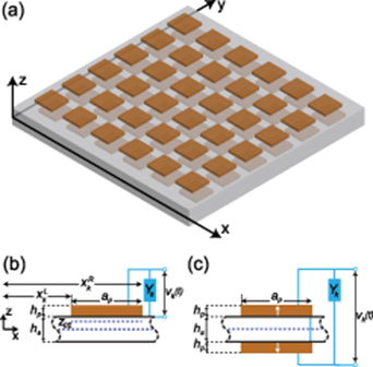
Figure 1. Schematic of a two-dimensional electromechanical metastructure. Close-up view shows the cross section of the thin plate with (a) single patch and (b) patch pair connected to kth shunt admittance. In case (b) patches are symmetrically placed on two surface sides and connected in series with the poling directions pointed out by white arrows.
Download figure:
Standard image High-resolution imageHere,  is the cross product of the two Heaviside functions in x and y directions, indicating the edge coordinates of the kth piezo-patch:
where  ,
,  ,
,  , and
, and  indicate the left, right, down, and upper edge coordinate of kth piezo-patch in x- and y-axis, respectively. Having substituted the internal moments in equations (7), (8) into (1), the governing partial differential equation of the plate with array of piezo-patches, and current balance equation in each piezo-patch are
where θ is the electromechanical coupling term in physical coordinates; Cp,k , Yk , and vk (t) are the piezoelectric capacitance, the load admittance, and the voltage across the kth electrodes of single or paired patch respectively. Here, it is worth noting that we obtain the output charge of each piezo-patch by integrating the electric displacement in equation (3) over its electrode area with different thickness coordinates. Thus, the strain distribution under each piezo-patch is accounted for when finding the electric output. This approach accurately calculates the output power of piezoelectric patches, but could underestimate the resonance frequency in cases where we have strongly coupled system [30].
For the unsymmetrical patch configuration, D11(x, y) and D12(x, y) are the flexural rigidity functions, m(x, y) is the mass per unity, given by
and for the symmetrical configuration:
One should note that the neutral axis location for the unsymmetrical patch configuration is not the mid-plane anymore. In fact, for general asymmetric piezoelectric plate composites, the neutral axis is not a straight plane but rather a curve plane [31, 32]. Also, by considering the stress-equilibrium equation, one could find that the neutral plane is not only dependent on physical and geometrical properties but also on external electric/mechanical load. In this study, however, we have derived the neutral axis location in equation (16 e) by assuming the short-circuit condition, that is E3 = 0. We have shown in our previous study that such an assumption holds well for the case of small-amplitude vibration of thin plates, when comparing with 3D finite-element simulations [29]. Moreover, it facilitates the calculation of displacement and electrical responses.
Based on the assumed modes expansion, the transverse displacement of the beam can be expressed as
where µmn (t) are the modal coordinates; ϕmn (x, y) are the assumed mode shapes of the plate with array of piezo-patches. Because of the geometric discontinuities introduced by the patches, using the exact solution would be cumbersome. Therefore, the natural frequencies are obtained using the characteristic orthogonal polynomials as the trial functions in the Rayleigh-Ritz method which is an approximate solution to the differential eigenvalue problem [33–35]. By normalizing the spatial coordinates as η = x/a and ξ = y/b , the orthonormal polynomials in can be generated through Gram-Schmidt process in the intervals of 0 ≤ η ≤ 1 and 0 ≤ ξ ≤ 1 as [33]
The first polynomial component X0(η) is a normalized trial function which satisfies the boundary conditions, a fully clamped plate (CCCC) in this case, given by [33]
The same procedure can be followed for constructing the Yn (ξ) polynomials with n = 1, 2, ..., N . Next, writing the Rayleigh quotient in the form of a ratio of the potential energy to the kinetic energy of the electromechanical system (see [33, 36, 37] for the details of the energy expressions), and minimizing it with respect to the coefficients Aij , yields the following algebraic eigenvalue equation

where for the unsymmetrical configuration, the mass and stiffness matrix of the electromechanical system are
One can obtain the mass and stiffness matrix for the symmetrical configuration too by multiplying the piezoelectric related components with two and removing all the terms associated with the neutral surface term z0. Further, the assumed mode shapes, referred to as Ritz eigenfunction [34] are
Analogous to the orthogonality conditions of the eigenfunctions in distributed parameter systems, substituting equation (27) into (10), multiplying by some plate mode shape, and integrating over the surface area of the plate [38], the governing equations in modal coordinates can obtained as
where θmn,k is the electromechanical coupling term for the kth piezo-patch, and fmn (t) is the modal forcing input, written as

Applying the Laplace transformation on equations (35) and (36), the modal coordinates can be written in terms of the voltages as
where the voltages can be obtained using the matrix inversion as

Here, ![$\mathbf{V} = \left[V_1(s), V_1(s), ..., V_P(s)\right]^T$](https://content.cld.iop.org/journals/0022-3727/53/50/505304/revision5/dabb5d5ieqn28.gif) includes the voltage across the electrodes of a single(paired) piezo-patch;
includes the voltage across the electrodes of a single(paired) piezo-patch;  is a square matrix of size P × P , and
  is column vector of size P × 1, given by
where F0 is the input force amplitude.
3. Numerical results
3.1. Locally resonant bandgap formation
In order to create bandgap in the host structure at a target frequency, each piezo-patch should be shunted to an inductive element Lk , enabling a resonating circuit. Here, we also include the resistive element Rk in parallel connection to the piezo capacitance and inductance, to complete a so-called parallel RLC resonance circuit. The existence of Rk allows us to tailor the electrical quality factor, which is important for creating sharp attenuation in the bandgap region, as demonstrated in the next subsection. By creating a parallel electrical resonance circuit, the admittance of each branch shown in figure 1(b) and (c) in Laplace domain becomes:
where the inductance value is chosen according to the target frequency of interest ωt as:

Now, the analytical formulation given in equations (27), (39) and (40) can be used to obtain the transmissibility FRF between the input force and output location as:
For a representative plate with dimensions of 0.8m × 0.7mm and a continuous piezo layer with a grid of 10 × 10 seperate electrodes, the transmissibility amplitude is shown in figure 2, for both cases of single and double side coatings. The geometric and material properties used for the numerical studies are give in table 1.
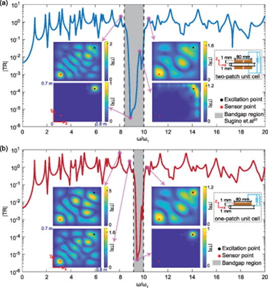
Figure 2. Transmissibility frequency response functions between the input forcing point at  and output point at
  for (a) single-sided and (b) double-sided piezoelectric metamaterial plate. The inset contour plots represent surface transmissibility amplitude for (a) ω/ω1 = 8.1, 8.9, 9.6, 10.4 with
  and (b) ω/ω1 = 8.0, 8.8, 9.5, 10.2 with
  . The resistance value in parallel to the inductance is 1 MΩ to make a high quality-factor resonance circuit. The mechanical damping ratio ζ is 0.5% for all vibration modes.
Download figure:
Standard image High-resolution imageTable 1. Geometric, material and electroelastic properties for thin aluminum plate and PZT-5H piezoelectric patch.
| parameter | value | parameter | value |
|---|---|---|---|
| hs | 1 mm | hp | 1 mm |
| ρs | 2700 kg.m−3 | ρp | 7500 kg.m−3 |
| Ys | 69 GPa |

| 66.1 GPa |
| νs | 0.33 |

| 19.2 GPa |
| a | 0.8 m |

| 23.5 GPa |
| b | 0.7 m |

| −23.4 C.m−2 |

| 17.3 nF.m−1 |
For validating our model, we compared the bandgap region with the analytical prediction by Sugino et al [27]. In their study, they have derived a simple yet powerful expression for estimating the frequency region where the dynamic flexural rigidity of the system becomes negative, i.e. bandgap formation [27]. However, their prediction is only valid for uniform coverage of piezo layers on the substrate, so that flexural rigidity of the system is constant for all coordinates. Given the assumption of continuous piezo layer coating on the substrate, the bandgap frequency range lies in the following interval [27]:
where α is a dimensionless term representing the system-level electromechanical coupling term, and is obtained as [27]:
where:
For the parameter values given in table 1, the dimensionless α value is around 0.422. Plugging this value into (45) determines the bandgap edge frequencies as shown by the dashed lines in figure 2(a). The bandgap region from the transmittance FRF curve matches perfectly with the one from the referred formulation. Although the plate boundary condition used here is fully clamped as opposed to simply supported condition in Sugino et al [27], the bandgap estimate is valid. This is due to the fact that the bandgap formation is independent of the type of mechanical boundary condition in the finite piezo-plate metamaterials. Moreover, for the single-sided piezo-plate metamaterials, the bandgap formation is shown in figure 2(b). It is worth noting that the bandgap width is about half of the one in the double-sided configuration.
Besides the point FRF graphs, the amplitude of transmittance for all locations of the metamaterial plate is shown in the insets of figure 2(a) and (b). The surface transmittance amplitude map are shown for four frequency points from before to middle and after the bandgap region. The corresponding transmissibility amplitude maps for points inside the bandgap in both single- and double-sided configuration confirm the bandgap formation in the entire surface of the piezo-plate metamaterial except the small region around the excitation point. The transmissibility amplitude map of the system for the entire frequency range in the proximity of the bandgap range is also presented in supplementary movies 1 and 2 (http://stacks.iop.org/JPhysD/53/505304/mmedia).
3.2. Transition from broadband shunt damping to bandgap formation
Piezoelectric shunt damping has been well researched over the past two decades, where different techniques including adaptive multimodal methods [39, 40] and synthetic circuit implementations [41, 42] have been proposed. Recently, as an extension to shunt damping approach ,the piezoelectric metamaterial plates have been shown to be promising in creating low-frequency bandgap formation [21, 24, 25, 27]. The admittance of shunt circuitry within these electromechanical metamaterials enables a great control over the effective stiffness of the host structure. Here, using the models developed in the modal analysis section, we aim to investigate the transition between the formation of locally resonant bandgap and broadband shunt damping.
The resonant shunt circuit used with the piezoelectric metamaterial comprises of a parallel RLC (shown in inset of figure 2(a)). The electrical quality factor for such resonant circuit is defined as:
Here, the capacitance of piezoelectric arrays are fixed and the inductance value is chosen according to the target bandgap frequency. Therefore, the resistive value can easily change the electrical quality factor at a given frequency. The effects of increasing the resistive value from lowest (close to short-circuit condition) to highest (close to high quality-factor resonant circuit) are shown in figure 3 and figure 4. The drastic changes in the displacement response of the metamaterial plate prove the dominant effect of electrical quality factor on the structure's effective stiffness. Interestingly, the transmissibility plot in figure 3(b) for R = 10  shows a flat response nearby the target frequency (from around 6ω1 to 20ω1) which represents the broadband shunt damping effect. In contrast, using large resistive values
  shows a sharp attenuation, yielding a locally resonant bandgap as shown in figure 3(c). Moreover, one can easily tune the inductance of each resonant circuit and obtain different target frequencies using equation (42), as shown in figure 5. The shaded gray region shows the analytical estimation of bandgap width given in (45) which confirms the simulations.
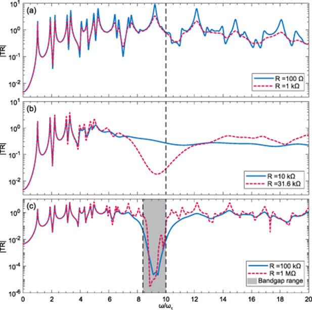
Figure 3. Transition from (a) short-circuit condition to (b) broadband shunt damping and (c) locally resonant bandgap formation via a varying resistance. Transmissibility FRFs are between the input forcing point at  and output point at
  for double-sided piezoelectric metamaterial plate. The mechanical damping ratio ζ is 0.5% for all vibration modes.
Download figure:
Standard image High-resolution image
Figure 4. Surface transmissibility amplitudes for a range of resonant circuit quality factors. With target bandgap frequency of  , top and bottom rows show the TR amplitude maps for ω/ω1 = 9, and ω/ω1 = 11, respectively. Black circle represents the point force excitation, and red circle is the readout point for |TR| FRFs shown inf figure 3.
Download figure:
Standard image High-resolution image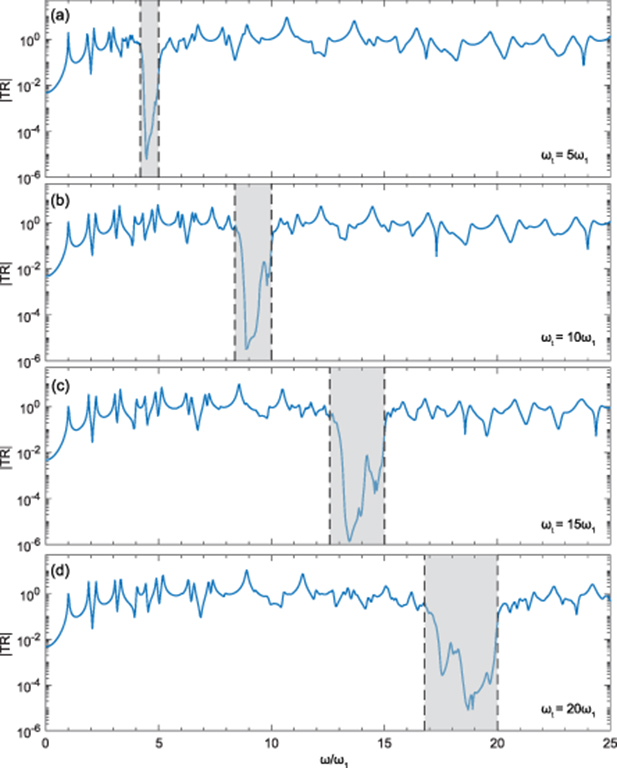
Figure 5. Tunability of the target bandgap frequency via change of circuit parameters. (a)  ,
,  (b)
(b)  ,
,  (c)
(c)  ,
,  (d)
(d)  ,
,  . The gray region shows the bandgap width, accurately validated by equation (45).
Download figure:
Standard image High-resolution imageWe should note that each electromechanical resonator has a coupling factor, which depends on the material properties of the piezoelectric element, structural damping of the host system, and electrically induced damping. When each piezoelectric patch is in open-circuit condition or connected to a high resistive load, the quality factor of the system is constant. In order to increase it, one should increase the electromechanical coupling between the piezo and plate structures, by optimizing the geometrical and material properties of the piezo patches. This approach is not the scope of our study as we have previously presented effects of different system parameters on electromechanical coupling coefficient and hence the quality factor of each unit [37]. Besides, even with an optimized quality factor of an electromechanical system, there will not be a bandgap formation if not for the presence of the inductance in the piezoelectric circuit. For low-frequency bandgap phenomena, we introduce the inductive plus resistive components to each piezoelectric patch to create an electrical circuit resonance. This way, we can control the dynamic stiffness of the whole system by tuning the inductance value, which enables us to control the bandgap frequency. Therefore, our approach allows us, for an already designed electromechanical system, to change the electrical circuit quality factor and thus control the bandgap and its transition to broadband shunt damping.
Furthermore, to understand the effect of electrical quality factor on the overall surface response of the metamaterial plate, the transmissibility maps are shown in figure 4. For a frequency point, ω/ω1 = 9 (inside the bandgap), the increase in R or  shows the increase in bandgap formation capability. However, for ω/ω1 = 11 (frequency outside the bandgap), the increase in R or
  illustrates the increasing and then decreasing trend in shunt damping performance. Such an unprecedented control over the effective stiffness of the metamaterial plates could be useful for tailoring the system response in different situations. For instance, if both bandgap and broadband damping properties are required, medium quality factors like the
  case in figure 4 can be selected.
3.3. Discrete local resonators
For bandgap formation in piezoelectric plate-type metamaterials, a sufficient number of local resonators is required to make the effective flexural rigidity of the system negative in the frequency range given in (45). The increase in numbers of resonator and hence successful bandgap formation would be possible in two ways: (1) electrode segmentation on uni/bi-morph piezoelectric plate, where piezoelectric layer covers the full area of the host substrate; (2) discrete placement of resonators, where an array of piezo-patches are distributed on the host plate with a physical separation.
The first method was modelled by Sugino et al [27] and has been used for our model validation in prior sections. It should be noted that the first approach simplifies the modal analysis modelling due to the existence of constant flexural rigidity on all surface coordinates of the system. However, in some practical applications, the second approach could be more feasible due to the facile piezo-patch attachment on beams/plates as presented in these experiments [21, 23, 28, 43, 44]. The developed analytical framework in this study provides a system-level modal analysis modeling of such discrete piezoelectric plate-type metamaterials. The use of Heaviside functions in equations (9)–(11) allows us to account for discontinuous flexural rigidity of the metamaterial plate in the modal analysis formulations. This means that the spatial coordinates as well as mass and stiffness components of each piezo-patch is taken into account, when constructing the eigenvalue equation in (30). Consequently, any random distribution of the resonators could be modelled using the developed framework.
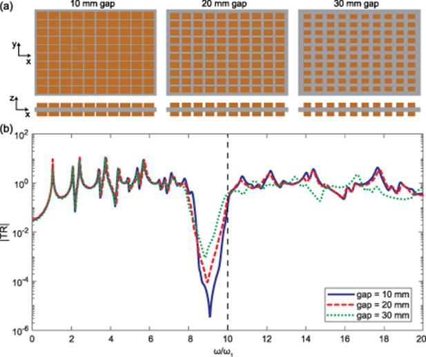
In order to understand the effect of physical segmentation of local resonators, the transmissibility FRFs are calculated for three gap sizes of 10 mm, 20 mm, and 30 mm, with 10 × 10 resonator grid, as shown in figure 6. Although the bandgap formation is clear in all cases , the sharpest attenuation is observed for the lowest physical gap between the resonators. This could be attributed to the unit-cell size, where the larger ones allow better electromechanical coupling, and hence sharper bandgap. The rationale behind such case study is to show the effect of electromechanical coupling of the resonators on the bandgap quality, while their electrical quality factor is at their maximum value. Furthermore, we can see that the transmissibility for different gap is more significant at higher frequencies because of the following reasons. Firstly, at higher frequencies, the flexural modes reach a wavelength comparable to the piezo-patch size, and the gap size can affect the mode shapes and resonant frequencies substantially. Secondly, at lower frequencies, the mode shapes have wavelength much larger than each unit cell, and thus the system's mass and stiffness components at those modes are not sensitive to change in the gap or size of unit cells.
Figure 6. Bandgap formation with discrete resonators. (a) Schematics of 10 × 10 piezo-patch array on the host structure with three different gap sizes (b) Transmissibility FRFs for three different gap sizes. Transmissibility FRFs are between the input forcing point at  and output point at
  for double-sided piezoelectric metamaterial plate. The mechanical damping ratio ζ is 0.5% for all vibration modes.
Download figure:
Standard image High-resolution image
4. Conclusion
Two-dimensional electromechanical metamaterials made from a thin plate with an array of piezoelectric elements connected to resonant shunt circuits can display bandgap for vibration reduction in aerospace, marine, and automotive applications. In this study, we developed a modal analysis framework for thin plates with an array of piezo-patches shunted to resonating circuits for investigating the bandgap formation. First, for a bimorph metamaterial plate, the bandgap formation was validated by an estimated formula from the literature. Then, for the unimorph metamaterial plate, it was shown that the bandgap frequency width is about half of the one in the bimorph configuration. The numerical studies were also performed to investigate the role of the quality factor of resonators. It was shown that the increase of Q factor is critical for transitioning from broadband shunt damping to the emergence of bandgap in metamaterial plates. Finally, the effects of the physical gap between the discretely-placed resonators were investigated, where the larger gap sizes yielded shallower bandgap formation. The future work will investigate the random distribution of the resonators on the host plates using the developed framework, which could be essential for accounting the experimental errors, and understanding the non-periodic placement effects on the bandgap formation.