
Abstract
Because of the limitations of thin-layer plasma for electromagnetic wave attenuation, a new PS-AWV (plasma-superimposed artificial wave vector) metasurface structure is proposed. We also introduced the design principle of increasing the propagation distance of electromagnetic waves in plasma using artificial wave vector metasurface. We designed a X band artificial wave vector metasurface by geometric phase dispersion control such that the incident electromagnetic wave abnormally reflected, and the reflection angle reached 55° when measured at normal incidence. Using an electromagnetic finite element method, we established a coupling model of the PS-AWV metasurface structure attenuated electromagnetic wave using CST (Computer Simulation Technology). We analyzed the variation law of reflectivity under different plasma parameter distribution, and the experiment was performed in a microwave darkroom. We also measured the reflectivity of the wave-vector metasurface structure. Both simulation and experimental results show that the artificial wave vector metasurface can effectively increase the attenuation effect of plasma on electromagnetic waves and improve the attenuation effect of electromagnetic waves because of thickness reduction; thus, it can reduce the plasma thickness required for plasma stealth and improve its application in practical scenarios.
Export citation and abstract BibTeX RIS

Original content from this work may be used under the terms of the Creative Commons Attribution 3.0 licence. Any further distribution of this work must maintain attribution to the author(s) and the title of the work, journal citation and DOI.
1. Introduction
Because of the continuous development of anti-stealth technology, a new stealth technology based on broadband and wide-angle active absorbing materials is the trend of next-generation stealth equipment. At the macro level, when the wave hits on plasma, we observe multiple types of propagation such as reflection, refraction, and attenuation. However, at the micro level, the response of free electrons in plasma to the electric field component of electromagnetic wave changes the propagation characteristics [1–3]. For aircrafts, the thinner the discharge chamber of the RF (radio frequency) plasma, the better it is to install and use the strong scattering parts such as the leading edge of the wing and the radar cabin; however, the thin-layer transmissive chamber structure will affect the characteristics of plasma discharge. The reduction in plasma thickness reduces the transmission distance of the radar wave in the plasma, and the amplitude of the electromagnetic wave attenuation is reduced [4, 5]. Studies at the University of Tennessee have shown that when the plasma electron density ranges from 2.8 × 10¹⁷ m−3 to 2.7 × 10¹⁸ m−3 and the thickness is 0.3 mm, the maximum attenuation at the frequency of 15 GHz is only 0.02 dB [6]. That mean there is basically no stealth effect. These results indicate that the plasma must have a certain thickness to have the effect of attenuating electromagnetic waves; however, when the closed plasma is thicker, it causes problems such as weight increase, difficulty in conformalizing with the body, and insufficient mechanical strength, which considerably increases the difficulty of engineering application.
When designing plasma-based stealth technology, radar-absorbing materials and plasma should simultaneously cover the aircraft's surface to reduce the plasma's thickness and improve the plasma's stealth effect [7, 8]. Chaohui et al used the FDTD (finite-difference time-domain) method to analyze the response of electromagnetic waves to conductive plates covered by plasma and radar-absorbing materials. In a higher frequency band, compared with metal plates covered by pure plasma or radar-absorbing materials, the composite structure covered by plasma on the absorbing material has a wave-absorbing effect. When the absorbing material covers the plasma, the absorbing band shifts to a lower frequency and the parameters of the plasma and the absorbing material are optimized such that the absorbing bandwidth is increased [9]. Yuan et al proposed a four-layer structure containing good conductors, absorbing materials, plasma, and non-destructive transport materials. Both the reflection and absorption characteristics of electromagnetic waves were studied via impedance transformation. Moreover, the effect of plasma and absorbing materials on RCS (radar cross section) reduction was confirmed [10]. Multilayer structures are a simple superposition of two absorbing materials and have limited effect on reducing plasma thickness. The absorbing material's function is to absorb a part of the incident electromagnetic wave that does not help the absorbing effect of the plasma itself. To achieve the absorbing effect, radar-absorbing materials need to have a certain thickness, which can lead to maintenance-related problems.
Artificial wave vector metasurface material is an electromagnetic wave propagation mode regulation technology that is based on the phase structure of surface structure. It can manually interfere with the reflection direction of electromagnetic waves [11]. When both the artificial wave vector super surface material and the plasma are superimposed, the propagation distance of the electromagnetic wave in the plasma significantly increases, and the radar wave attenuation effect improves. In this study, for attenuating electromagnetic waves, we propose the theory and method of a PS-AWV metasurface composite structure. We designed the metasurface structure of singular reflection and established the theoretical model of superimposed artificial wave vector metasurface. The reflectivity of the superimposed structure was obtained by simulation, and the superposition structure could effectively reduce the reflectivity. Finally, we performed experimental verifications, and the results obtained were basically consistent with the simulation results.
2. Cell design and singular reflection verification
The phase gradient metasurface can realize the regulation of the reflection direction of the reflected wave. When designing the unit, to generate magnetic resonance, the back of the thin dielectric substrate is coated with a layer of metal, and the front side is loaded with a metal patch that can be coupled with the metal back sheet. By changing the patch size, the phase of the reflected wave can be adjusted. For adjusting the direction of electromagnetic wave reflection, when the phase difference covers the range of 2π, a reasonable phase gradient is designed, and the cells are arranged in a matrix to obtain a 2D reflection phase gradient metasurface.
Figure 1(b) shows the unit structure designed in this study. The dielectric substrate is FR4 (εr = 4.5 and tan δ = 0.025), the side length l is 6 mm, and the thickness h is 1.52 mm. The back side of the substrate is coated with metallic copper, and the front surface structure is an 'H'-shaped metal piece. This structure can effectively reduce the cell size (0.49 ), which is shown in figure 1(b). When the electromagnetic wave is incident on the unit's surface, the metal structure on the unit's front side is coupled with the metal plate to generate magnetic resonance, which changes the reflection phase of the electromagnetic wave. By fine tuning the size of the patch, different reflection phases are generated, thereby changing the direction of the reflected wave and realizing the abnormal emission. The frequency m is scanned by the electromagnetic simulation software CST Microwave Studio, and the result is shown in figure 1(d). At the center frequency of 10 GHz, six cells with a phase interval
  between adjacent cells of 60° are selected to construct a supercell. Table 1 shows the corresponding phase.
Table 1. Parameters corresponding to the unit at 10 GHz.
| Length of m of six units (mm) | Corresponding phase (°) | |
|---|---|---|
| 1 | 1.50 | −342.72 |
| 2 | 5.44 | −403.85 |
| 3 | 6.05 | −462.71 |
| 4 | 6.40 | −520.82 |
| 5 | 6.80 | −581.80 |
| 6 | 8.38 | −642.16 |

Figure 1. (a) Artificial wave vector super surface, (b) unit structure, (c) reflectivity measuring device, and (d) selected six units.
Download figure:
Standard image High-resolution imageAccording to the generalized Snell's law of reflection (the medium is air and the refractive index n ≈ 1):
where  is the angle of reflection,
  is the angle of incidence,
  is the wavelength of the electromagnetic wave in free space, and
  is the phase gradient of the length of the element. Then using (1), we obtain the following:
When the incident wave is perpendicularly incident, equation (2) is simplified as follows:
The theoretical value of the reflection angle obtained by substituting 10 GHz for the wavelength  and
and  for (3) is 54.5°.
The full-wave simulation is performed using the frequency domain solver of the simulation software CST, the selected cells are sequentially arranged along the x-axis to form a phase gradient metasurface, and the x-polarized wave is perpendicularly incident on the metasurface along the z-axis direction. Figure 2 shows the electric field distribution at 10 GHz. The reflected wave deviates from the normal incidence direction and the reflection angle is ~55°, which agrees with theoretical calculations.

Figure 2. Electric field distribution at 10 GHz at normal incidence.
Download figure:
Standard image High-resolution imageTo confirm the feasibility of the scheme, the artificial wave vector metasurface was obtained by machining and its scale are 400 mm × 400 mm × 1.52 mm. As shown in figure 1(a), we used the far field reflectance measurement and the near-field distribution measurement to measure the surface plasmon coupling efficiency and surface electromagnetic wave propagation of the artificial wave vector metasurface. Figure 1(c) shows the reflectivity measuring device. Figure 3 shows a comparison of the measured artificial wave vector metasurface frequency domain response with the simulation results. The measurement results are in good agreement with simulation results. The anomalous reflection effect generated by the 'manual wave vector' effectively reduces the amount of reflection when the electromagnetic wave is incident normally. At 10.8 GHz, the maximum attenuation is 14.7 dB.

Figure 3. Frequency domain reflectivity of artificial wave vector metasurface.
Download figure:
Standard image High-resolution image3. Attenuation of electromagnetic waves by PS-AWV metasurface structure
3.1. Plasma density measurement experiment
In this paper, the radial electron density of plasma is measured by microwave interferometry. The microwave interferometry is to calculate the equivalent dielectric constant of the plasma by measuring the phase shift of the wave, and then obtain ne.
Limited by the wavelength of the interference wave and the plasma scale, the microwave interference method cannot directly apply the spatial distribution diagnosis of small-size discharge, and can only diagnose the string average ne on the interference wave propagation path. Generally, the frequency of the interference wave is much larger than the plasma frequency. When the pressure is in the range of 1 pa–100 pa, the influence of the collision on the  can be neglected.
  can directly obtain the line integral on the transmission path by the formula (4).
When the wave interference method is used to diagnose the distribution on the detection path, an additional means must be introduced to obtain the contour function. The method in this paper is to approximate the contour curve by using the solution of the diffusion equation under steady-state conditions. For a uniformly diffused particle source, the steady-state diffusion equation is the Poisson equation [12],  . According to the excitation mode of the inductively coupled plasma, the energy injection region can be approximated as a cylindrical shape. For a given cylindrical plasma with radius R, in azimuthally symmetric coordinate system, the diffusion equation becomes:
The boundary condition of the diffusion equation is the maximum at the axis and zero at R, then the complete solution of the diffusion equation is a parabola:
Limiting the discharge gas to an electropositive gas. In the cylindrical coordinate system, the diffusion equation becomes (7), The solution of the diffusion equation is a zero-order Bessel equation, where  and
and  is the peak of ne.
The wheelbase of the entire quartz chamber is short, the wheelbase of the chamber is close to the wavelength of the interference wave, and the phase shift of the interference wave generated in the plasma is small. According to the method in [13], this paper uses a dual-port standard gain horn antenna S12 measurement scheme, which can more accurately measure the phase shift of thin layer plasma. It should be noted that in the discharge, the plasma will be significantly unevenly distributed. When using the microwave diagnostic method, it is necessary to move the central axis position of the antenna to maximize the phase shift amount.
When the air pressure is 10 pa, the plasma density at different thicknesses and powers measurement results are shown in the figure 4. When the power is 500 W, the thickness is 5 cm, the plasma density at different pressures are shown in the figure 5.

Figure 4. Plasma density at different thicknesses and powers.
Download figure:
Standard image High-resolution image
Figure 5. Plasma density at different pressures.
Download figure:
Standard image High-resolution image3.2. Simulation study on reflectivity of superimposed structure
In this section, a space-time coupled model of plasma superposition artificial wave vector super-electromagnetic wave propagation is established using CST microwave studio. First, we establish a parameter distribution model of inductively coupled plasma (ICP). In the CST, the plasma can be directly defined by setting the plasma frequency and the collision frequency, and the electromagnetic properties of the plasma can be more realistically simulated compared to the plasma model defined by the in-built dielectric constant formula.
The RF power is 500 W and the pressure is 10 Pa. Figure 6 shows the plasma model in the 5 cm-thick chamber and the reflectivity simulation results of the plasma superimposed artificial wave vector super surface. After the addition of the metasurface, the amplitude of the reflectance significantly decreases, the bandwidth increases, and the maximum attenuation rate exceeds −40 dB. Bands with reflectivity below −5 dB include 0.53–1.07, 1.66–3.74, 6.6–11.38, and 11.53–12.08 GHz. These results prove that the artificial wave vector metasurface can effectively improve the attenuation effect of plasma on electromagnetic waves. In particular, for a thin layer of plasma with uneven electron density distribution, the artificial wave vector super surface can effectively increase the propagation distance of electromagnetic waves in the plasma, thereby enhancing the attenuation of electromagnetic waves by the plasma. However, because of the working bandwidth limitation of the artificial wave vector metasurface, the effect of reducing the reflectivity in the low frequency band is not obvious. In the range of 6–12 GHz where the metasurface is effectively operated, the average reflectance is reduced from −5 dB to −15 dB. Such results indirectly confirm that plasma as a main medium for attenuating electromagnetic waves has obvious advantages for absorbing bandwidth. Although we used various methods to increase the working bandwidth of the artificial wave vector metasurface, we still cannot cover all the absorbing bands of the plasma. Additional studies on the design of broadband artificial wave vector metasurface are required to strengthen the electromagnetic wave attenuation effect of PS-AWV metasurface structure.
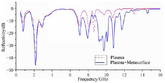
Figure 6. Simulation results of plasma reflectivity with or without superimposed artificial wave vector metasurface.
Download figure:
Standard image High-resolution image
Figure 7. Simulation results of 2.5 cm-thick ICP superimposed artificial wave vector metasurface reflectance.
Download figure:
Standard image High-resolution image
Figure 8. Simulation results of 5 cm-thick ICP-superimposed artificial wave vector metasurface reflectance.
Download figure:
Standard image High-resolution imageFigures 7–9 show the reflectivity simulation results of ICP-superimposed artificial wave vector metasurface structures with thicknesses of 2.5, 5, and 10 cm, respectively, at a gas pressure of 10 Pa. The comparison shows that, for different thicknesses of ICP, the reflectivity will be significantly reduced when the RF power is increased. Compared with the influence of RF power, when the thickness of the chamber increases, the reflectivity and the amplitude decrease and the bandwidth significantly increases. First, in the low frequency region below 3 GHz, because the artificial wave vector super surface cannot work in this frequency band, the attenuation of electromagnetic waves primarily depends on the plasma. Moreover, because of the long wavelength of the electromagnetic wave in the low frequency band, the response to the plasma thickness is more sensitive. When the thickness increases, the reflectance amplitude and bandwidth significantly improve. In the X-band where the artificial wave vector metasurface primarily works, the influence of the thickness on the attenuation effect of the electromagnetic wave is far less obvious than that of the simple plasma because of the change in the reflected wave path. Because electromagnetic waves propagate in the plasma more laterally, even with a 2.5 cm-thick ICP, the electromagnetic wave attenuation effect is relatively obvious. However, in the high frequency range of > 14 GHz, the ICP attenuation effect of 10 cm thickness is still better.

Figure 9. Simulation results of 10 cm-thick ICP-superimposed artificial wave vector metasurface reflectance.
Download figure:
Standard image High-resolution imageAfter superimposing the artificial wave vector metasurface structure, the simulation results of ICP reflectivity at different pressures are shown in figure 10. Compared with the simple plasma, the effect of plasma on the electromagnetic wave attenuation is improved at 1 Pa and at a higher pressure of 100 Pa. In particular, at 100 Pa, the attenuation bandwidth is considerably increased. The attenuation effect because of uneven plasma distribution under the original high pressure is insufficient, and it is obviously improved after superimposing the artificial wave vector metasurface. First, at high pressure, because the plasma frequency and the electromagnetic collision frequency are both high, the effective absorption band of the plasma moves toward a higher frequency. As can be seen from the figure, the first attenuation peak changed from 2.2 GHz at 10 Pa to 5.2 GHz at 100 Pa. Second, after superimposing the artificial wave vector metasurface, the electromagnetic wave propagated more in the radial direction in the plasma. At high pressure, the gradient of the plasma in the radial distribution changed very sharply, and multiple reflections of the electromagnetic wave occurred during the propagation. Refraction, which is equivalent to increasing the range of electron density distribution, increased the bandwidth of electromagnetic wave attenuation.
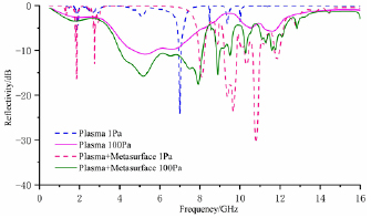
Figure 10. Simulation results of ICP superposition artificial wave vector metasurface reflectivity at different pressures.
Download figure:
Standard image High-resolution image3.3. Experimental study on reflectivity of superimposed structures
To confirm the attenuation effect of the superimposed surface of the plasma superimposed artificial wave vector on the electromagnetic wave in the previous section, relevant experiments were performed to measure the reflectivity of the superposed structure. Figure 11 shows the schematic of the experimental system. The angle between the antenna emission direction and the center of the chamber is 10°, and the sweep range of the vector network analyzer is set to 0.5–16 GHz. First, a metal plate is placed on the support and the reflectance is measured as a background reference value. Then, the artificial wave vector super surface and the quartz chamber are placed, the RF power source is turned on, and a plasma is generated in the quartz chamber. We adjusted the experimental conditions such as RF power and air pressure to measure the reflectivity of the superimposed artificial wave vector metasurface structure under different conditions. Figure 12 shows the schematic of the experimental equipment (The diameter is 200 mm. The direction of incidence of the electromagnetic wave is the axial direction, and the direction parallel to the metasurface is the radial direction). The air pressure conditions in the experiment are all 10 pa. Figure 13 shows the dimension and the cell configuration for the artificial wave vector metasurface section used in the experiments.
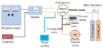
Figure 11. Schematic of the experimental system.
Download figure:
Standard image High-resolution image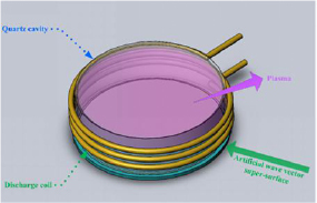
Figure 12. Schematic of the experimental equipment.
Download figure:
Standard image High-resolution image
Figure 13. The dimensions and the cell configuration for the artificial wave vector metasurface section used in the experiments.
Download figure:
Standard image High-resolution imageFigure 14 shows a comparison of the reflectance of a 2.5 cm-thick ICP and the reflectance measurement after superimposing the artificial wave vector metasurface. The plasma attenuation of electromagnetic waves is still weak when the RF power reaches 500 W because the electromagnetic wave traveling in the plasma is considerably short and cannot fully react with the plasma; therefore, the spatial distribution gradient of the thin layer ICP is very large. Because of the high potential in the chamber, the plasma appears as a very narrow circle. The annular distribution reduces the effective interaction area of the electromagnetic wave; however, after superimposing the artificial wave vector super surface, the reflectivity is considerably reduced at 300 W, and the reflectance is further lowered when the power increases to 500 W. Compared with simulation results, the actual ICP electron density is lower than the simulation result because of the power loss in the experiment. Therefore, the experimentally measured reflectance is higher than the simulation result, and the maximum attenuation bandwidth for the electromagnetic wave is determined using X, and the band is reduced to the C band.
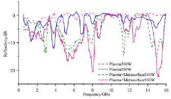
Figure 14. Plasma reflectance measurement results with or without superimposed artificial wave vector metasurface.
Download figure:
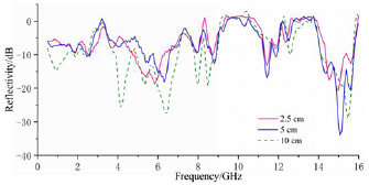
Standard image High-resolution imageFigure 15 shows the comparison of reflectance measurements of three different thicknesses of ICP-superimposed artificial wave vector metasurfaces at a RF power of 700 W. After superimposing the artificial wave vector super surface, the influence of the thickness on the plasma reflectivity reduces because the abnormal reflection of the surface of the artificial wave vector changes the propagation path of the reflected wave in the plasma. The electromagnetic wave propagates more radially from the axial direction, which weakens the influence of the thickness.
Figure 15. Measurement of metasurface reflectance of artificial wave vector with ICP superposition of different thicknesses.
Download figure:
Standard image High-resolution image
4. Conclusion
In this study, we proposed the metasurface structure of PS-AWV and introduced the principle of increasing electromagnetic wave attenuation. To overcome the limitations reported in the current research, we designed an ultra-surface structure that can adjust the electromagnetic wave propagation vector in X band. A PS-AWV metasurface model was established using CST. Moreover, using thin-layer plasma as the mainabsorbing medium, the artificial wave vector metasurface artificially intervened in the reflected wave vector of the electromagnetic wave to ensure the near-surface 'artificial wave vector' improved the propagation distance of the electromagnetic wave in the plasma. Furthermore, the reflectivity of the superposed structure was obtained by simulation and experimental methods. The results show that the superposition of artificial wave vector metasurface structure by plasma can effectively reduce the reflectivity and that the attenuation of electromagnetic waves is better than that of pure thin-layer plasma. In this manner, the PS-AWV super surface structure designed in this study has a stealth effect. Because of the anomalous reflection of the artificial wave vector metasurface, the propagation path of the reflected wave in the plasma changed. The reflected wave primarily propagated from the axial direction to the more radial direction; therefore, the chamber thickness attenuated the electromagnetic wave and the degree of influence is weakened. Furthermore, the uneven effect of the electron density distribution caused by the high gas pressure on the plasma absorbing effect improved because of abnormal reflection.
Acknowledgment
This paper was supported by the National Natural Science Foundation of China (No. 11805277) and China Postdoctoral Science Foundation (No. BX20190378).