
Abstract
The current establishment of stretchable electronics to form a seamless link between soft or even living materials and the digital world is at the forefront of multidisciplinary research efforts, bridging physics, engineering and materials science. Magnetic functionalities can provide a sense of displacement, orientation or proximity to this novel formulation of electronics. This work reviews the recent development of stretchable magnetic field sensorics relying on the combination of metallic thin films revealing a giant magnetoresistance effect with elastomeric materials. Stretchability of the magnetic nanomembranes is achieved by specific morphologic features (e.g. wrinkles or microcracks), which accommodate the applied tensile deformation while maintaining the electrical and magnetic integrity of the sensor device. The entire development, from the demonstration of the world's first elastically stretchable magnetic sensor to the realization of a technology platform for robust, ready-to-use elastic magnetosensorics is described. Soft giant magnetoresistive elements exhibiting the same sensing performance as on conventional rigid supports, but with fully strain invariant properties up to 270% stretching have been demonstrated. With their unique mechanical properties, these sensor elements readily conform to ubiquitous objects of arbitrary shapes including the human skin. Stretchable magnetoelectronic sensors can equip soft and epidermal electronic systems with navigation, orientation, motion tracking and touchless control capabilities. A variety of novel technologies, like electronic skins, smart textiles, soft robotics and actuators, active medical implants and soft consumer electronics will benefit from these new magnetic functionalities.
Export citation and abstract BibTeX RIS

Original content from this work may be used under the terms of the Creative Commons Attribution 3.0 licence. Any further distribution of this work must maintain attribution to the author(s) and the title of the work, journal citation and DOI.
1. Introduction
Stretchable electronics [1–4] has become one of the most vital technological research fields of recent years, aiming to revolutionize common electronic systems towards being arbitrarily re-shapeable on demand after their fabrication, particularly on large areas. Especially compliant designs of inorganic semiconductor [5–7] and metal-based [1, 5, 7–15] electronics combine the advantages of being soft with the high speed and low power consumption capabilities of conventional semiconductor-based electronics [7, 16–19]. In this respect, stretchable devices are able to accommodate tensile strains much larger than 10%, without sacrificing their performance. For this purpose, these electronic systems have to reversibly accommodate tensile strains far beyond the intrinsic ductility of the active electronic materials they are made of.
A large variety of compliant organic and inorganic electronic elements with various functions have been realized in the last years, which are summarized in figure 1. These devices include light emitting diodes (LEDs) [22, 23], heaters [17, 21, 24], actuators [8, 15, 18, 19, 21, 25] and supercapacitors [26]. Stretchable sensoric devices can detect mechanical [11, 27–29], optical [12], thermal [15, 30] or bioelectric [31, 32] stimuli. The power supply of prospective soft electronic systems may be provided by incorporated stretchable solar cells [33, 34], energy harvesters [35–37] or batteries [19, 38]. Wireless powering and data transfer using stretchable antenna designs have also been shown [8, 39].

Figure 1. Overview of available functionalities in stretchable electronic devices: various capabilities have been demonstrated already. Stretchable magnetoelectronics, as reviewed in this work, adds magnetic functionalities and is also included as a member in this family. (Piezo-responsive electronics) From [1]. Reprinted with permission from AAAS. (Thermo-electronics) [15] John Wiley & Sons. © 2015 WILEY-VCH Verlag GmbH & Co. KGaA, Weinheim. (Integrated circuitry) From [1, 5]. Reprinted with permission from AAAS. (Wireless transmission) Adapted from [8] with permission of The Royal Society of Chemistry. (Magneto-electronics) [21] John Wiley & Sons. © 2012 WILEY-VCH Verlag GmbH & Co. KGaA, Weinheim. Reprinted by permission from Springer Nature Customer Service Centre GmbH: Nature Communications [17] (2015). (Opto-electronics) Reprinted by permission from Springer Nature Customer Service Centre GmbH: Nature [12] (2008). Reprinted by permission from Springer Nature Customer Service Centre GmbH: Nature Materials [7] (2010). (Batteries) Reprinted by permission from Springer Nature Customer Service Centre GmbH: Nature Communications [19] (2013). (Bio-interfacing electronics) Reprinted by permission from Springer Nature Customer Service Centre GmbH: Nature Materials [18] (2010).
Download figure:
Standard image High-resolution imageThe stretchable magnetic field sensor was introduced as a new member in the family of soft electronic devices [40]. Subsequently, shapeable magnetoelectronics [41], was defined as a more wide-spread concept which, besides stretchable [40], also incorporates flexible [42, 43] and printable [44–46] magnetosensitive elements. Up to now, there had been various distinguished publications regarding flexible magnetic sensors relying on giant magnetoresistive multilayers [17, 43, 47–52] and spin valves [48, 53–56], magnetic tunnel junctions [57, 58], anisotropic magnetoresistive [59, 60] and magnetoimpedance [61, 62] elements as well as Hall probes [42, 63, 64] and other magnetic sensor principles [58, 65]. While review articles focussing on flexible [41, 66, 67] and also printed magnetoelectronics are available [41, 46], this review is strongly dedicated to the emerging topic of elastically stretchable magnetic field sensorics as one key facet of shapeable magnetoelectronics. The realization of magnetic sensing elements that are elastic and ideally alter neither electrical properties nor their magnetoelectric response upon severe and repeated tensile deformations (strain invariance) was the main focus of this development so far.
1.1. Potential applications
The ability to sense, measure and respond to external magnetic stimuli paves the way to realize smart and soft electronic systems with appealing new features, like navigation, orientation, motion tracking and touchless human–machine interaction. Several application areas of compliant electronics that can benefit from magnetic functionalities are illustrated in figure 2.

Figure 2. Application fields of stretchable electronics: overview of applications for soft electronics with prospective potential for stretchable magnetic sensorics. (Electronic skins) Reprinted by permission from Springer Nature Customer Service Centre GmbH: Nature Communications [68] (2014). (Functional implants) Reprinted by permission from Springer Nature Customer Service Centre GmbH: Nature Communications [13] (2014). (Soft robotics) [14] John Wiley & Sons. © 2011 WILEY-VCH Verlag GmbH & Co. KGaA, Weinheim. (Smart textiles) Reproduced with permission from [69, 70].
Download figure:
Standard image High-resolution imageOne of the most prominent examples is the emerging field of electronic skins (e-skins) [39, 69–71], which are conformably positioned on biological tissue readily following all its natural motions and distortions. Stretchable magnetic sensorics leads electronic skin systems beyond imitating the characteristics of its natural archetype and extends their cognition to static and dynamic magnetic fields that by no means can be perceived by human beings naturally. This enables a sixth sense of magnetoception [72, 73] for artificial skin systems. In addition to being wearable, e-skins can also be operated in vivo as bio-integrated electronics [18, 74–76]. Magnetic sensing capabilities could include real time monitoring of muscles, joints or valves of the heart or allow remotely monitoring specific physiological actions and processes by highly functional and compliant diagnostic or therapeutic implants [32] as well as advanced surgical tools [77].
Another novel and highly innovative field of prospective applications for stretchable magnetic sensorics is soft robotics [14, 78] and particularly elastomeric actuators [25, 79]. Since the acquisition of motion and displacement has developed to be the main duty of magnetic sensorics in conventional machinery, a stretchable counterpart can adopt these functions into these soft systems, enabling accurate control of actuation. As for their rigid counterparts, keeping track of the current position of all its movable parts is an essential requirement for highly functional robots with multi-tasking abilities. This is even more vital to soft robots, as the displacement of actuating components is strongly dependent on the mechanical load on these parts. Control strategies relying on the feedback from magnetic motion tracking sensorics can provide a comprehensive, highly integrative and cost effective solution to this issue compared to e.g. optical approaches.
The ability to conform to arbitrary nonplanar surfaces can be of great advantage for the field of non-destructive material testing, which in case of metal parts prevalently relies on magnetic sensing [80]. Compliant forms of magnetic sensors can follow the shape of parts under test, which brings the sensing part much closer to the source of magnetic stray fields to be detected and are also able to allow for severe shape deviations of specimens in a high-throughput production process.
Foreseeable applications of highly sensitive and re-shapeable magnetosensorics also include the in-flow detection of magnetic particles or magnetically labelled analytes [51, 81], in advanced fluidics [82] and lab-on-a-chip [83] platforms, which may boost health monitoring, point-of-care diagnostics and environmental sensing capabilities into a new realm of possibilities. Furthermore, stretchable forms of consumer electronics [84] and smart textiles [85, 86] will benefit from magnetic functionalities offered by compliant magnetoelectronics.
1.2. Technological approaches
Depending on the desired properties (i.e. sensitivity, magnetic field range, sensitive direction, temperature behaviour, etc), there are several technologies available for the realization of magnetic sensing devices [87]. These include conventional Hall [88] and planar Hall [89] effect sensors, anisotropic magnetoresistance elements [90], magnetic tunnel junctions [91] and fluxgate magnetometers [92].
Magnetic materials revealing a giant magnetoresistance (GMR) effect are able to vary their electrical resistance by several tens of percent upon application of an external magnetic field [93]. The GMR effect was originally observed in thin film stacks of magnetic and non-magnetic metal layers deposited in an alternating order by molecular beam epitaxy [94]. For a high GMR effect in these multilayer films, an antiferromagnetic exchange coupling between the ferromagnetic layers occurring at very distinct thicknesses of the non-magnetic spacer layers and a good interface quality [95] are essential. Later, GMR multilayer films were mainly prepared by economically preferable magneton sputter deposition techniques [93]. This kind of magnetoelectronic thin films revealed high resistance changes of up to more than 65% at room temperature [96] and their field range of operation can be widely tuned by the selection of materials and layer structure [93]. The magnetoresistive characteristic is symmetric with respect to zero magnetic fields in general. Hence, without magnetic biasing, a sense of direction along a certain field axis is not comprised in GMR multilayer sensors. Also, hysteresis is an application limiting factor that cannot fully be suppressed in these structures.
Similar GMR multilayer structures can also be obtained by electrochemical deposition methods [97], which hold great economic potential, as it involves no vacuum processing. This fabrication approach also allows the growth of GMR nanowires. Electrochemically deposited multilayer structures exhibit much higher film thicknesses, which mainly creates magnetically uncoupled layers, resulting in lower GMR magnitudes.
Comparable GMR effects have also been observed in granular alloys containing magnetic particles in a metallic host, which do not require any layered structure [98, 99]. In most cases, the preparation of granular GMR material includes careful annealing procedures to obtain a desired particle size, shape and distribution.
More sophisticated GMR architectures are obtained utilizing the exchange bias interaction [100], occurring between ferromagnetic and adjacent antiferromagnetic thin films. The respective spin valve sensors [101] and magnetic tunnel junctions [91] offer high sensitivities, directional field discrimination and are prepared using magnetron sputtering. While spin valves can be large area thin film structures operated in a current-parallel-to-plane geometry, magnetic tunnel junctions, which involve the charge transport through a defect-free tunnel barrier, require micropatterned sensor elements with a current-perpendicular-to-plane architecture. For both types, hysteresis in the magnetoelectric response function is a mayor issue and needs to be reduced for magnetic sensor applications.
GMR-based sensor devices fabricated on rigid inorganic substrates, like oxidized silicon (SiOx) wafers or glass, are widely used in conventional and highly demanding sensoric applications [102, 103], due to their robustness, fast response and high sensitivity to magnetic fields in the sub-Oe to few kOe range.
GMR thin film structures have been chosen as the backbone for a magnetic sensorics technology suitable for the development of compliant and shapeable magnetosensitive devices [21, 41, 50, 57]. Processed into a powder and further to a homogeneous paste, GMR sensor elements were also printed onto arbitrary surfaces by conventional thick film technologies, for instance [44–46]. Several examples of flexible magnetoresistive films and sensing elements on different plastic sheets have also been demonstrated over the last years [47, 48, 50, 53, 54, 57], reaching bending radii in the low centimetre range. By directly applying tensile deformation by plastic stretching, functional GMR films could be tested beyond 2% strain [50]. This approach revealed a novel post-fabrication strategy to permanently adapt the sensor parameters by strain-tuning. In order to be able to elastically stretch GMR sensor elements to much higher levels of deformation, the magnetic nanomembranes should be placed onto an elastomeric substrate.
Several approaches to evolve layered electronic components into highly stretchable devices are known in the context of stretchable electronics [2]. The smart combination of thin metal films and soft polymeric membranes allows creating the technology platform for stretchable GMR based sensorics. The accommodation of high strains in thin films of intrinsically stiff materials is facilitated by morphologic features [104], e.g. wrinkles or microcracks, which are to be introduced into the system. They are able to transfer large tensile deformations of the substrate into minimal strains in the functional film [105, 106].
Soft magnetic sensor materials of non-layered GMR architectures may be feasible as well. For granular GMR materials, a suitable conductive matrix material that is also soft turns out to be the key, as well as the magnetic particle arrangement therein [107]. Electrodeposited GMR wires in a wavy or coiled architecture may be another alternative approach to obtain stretchable GMR elements.
1.3. Approaches towards stretchable electronics
Several approaches to build soft systems with high performance using rigid and brittle materials (like silicon, metals and ceramics) on top of elastomer membranes are known from the development of stretchable electronics [1, 2, 108]. The ones that are applicable to layered structures are summarized in table 1, including their key attributes, especially in the scope of magnetoelectronic elements.
Table 1. Approaches to stretchable thin film electronics: the table summarizes the key parameters of the discussed approaches to achieve stretchability in electronic systems. (Microcracks) Reprinted from [4], with the permission of AIP Publishing. (Meander patterns) [109] John Wiley & Sons. © 2004 WILEY-VCH Verlag GmbH & Co. KGaA, Weinheim. (Rigid islands) From [1]. Reprinted with permission from AAAS.
| Approach: | Microcracks | Meander patterns | Surface wrinkling | Rigid islands |
|---|---|---|---|---|
| Example: |  |
 |
 |
 |
| Difficulty: | Easy | Medium | Easy − medium | Demanding |
| Stretchability: | Low − medium | Medium − high | Medium | Low − high |
| Main applications: | Interconnects, capacitive sensors, biostimulation | Interconnects, medical sensors, antennas | Surface electrodes, integrated circuits, large area sensors | Complex electronic systems, epidermal electronics |
| Peculiarity: | Resistance changes element with stretching | Preferential with larger film thickness | Large area and extended films | Functional elements isolated from strain |
A thin metal film with a microcracked morphology, for example, as obtained when deposited on a rubber support under certain growth conditions [104, 106], remains electrically conductive for applied lateral strains beyond 20% [110]. Compliant metal interconnects that could be elastically stretched over more than 100 000 loading cycles [111], as well as conformable capacitive pressure sensors [11] were demonstrated using this approach. It is also possible to prepare compliant patterns (e.g. meanders) in films of rigid material using lithographic structuring methods. Similar to a spring, this approach effectively transforms the tensile deformation of the system to a bending of the rigid material [112], including significant out-of-plane distortions [113]. Metal meanders are mainly used to fabricate highly conductive stretchable interconnects [109], antennas [39] and epidermal contact pads for biosensing [114]. One of the most prominent approaches to stretchable electronic systems, however, is to exploit surface wrinkling, which occurs, if a thin layer of stiff material is deposited or laminated onto a pre-stretched elastomeric substrate upon subsequent relaxation of the pre-strain [115]. In the ideal case, a wrinkled nanomembrane can accommodate tensile strains by levelling out its buckles [105], without the generation of cracks, until the original pre-strain is reached [116] (i.e. the point where the film is flat again). This effect led to the design of various functional and highly integrated stretchable electronic systems [5, 26, 27, 33]. A further approach relies on mesh designs of distributed functional elements or clusters prepared on arrays of rigid islands, which are electrically linked by highly stretchable interconnects [117, 118]. Upon stretching, the compliant electrical bridges accommodate the lateral deformation, while the functional islands ideally remain unstrained and only adjust their distance to each other. Many complex and multifunctional electronic systems have been realized using this approach [7, 19, 30, 77, 119, 120].
Often two or more of these approaches are combined in order to reach the desired mechanical properties. If the rigid islands of a compliant mesh design are combined, for example, with sophisticated meander patterned interconnects, stretchabilities of several hundred percent are possible [19].
1.4. Compatibility to magnetic sensorics
With respect to GMR nanomembrane-based sensorics, the above mentioned approaches have different advantages and disadvantages. A microcracked thin metal film, for instance, is easy to fabricate on elastomeric substrates, but leads to elements with varying resistance upon stretching [110, 121], which is of great disadvantage for (magneto-) resistive sensor devices. Furthermore, the strong morphological transitions and induced local strains associated with stretching can in particular have a strong influence on the magnetic properties of magnetic thin films [122–124] and are thus expected to alter the sensor response of GMR structures. The use of compliant meander structures for stretchable magneto-sensorics seems feasible. However, due to the large local stresses imposed on the functional layer at higher strains, demanding preparation procedures would be needed in order to prevent the GMR layer stacks, with a total thickness of about 100 nm only, from breaking. Surface wrinkling is very promising, as it allows closed large area membranes to be stretched without cracking. In the case of wrinkled magnetic nanomembranes, however, the local out-of-plane tilting on the sides of the buckles may cause an influence on the sensor response due to the resulting local out-of-plane components of in-plane applied magnetic fields. Compliant mesh designs would allow for large arrays of conventional GMR sensor dies on the rigid islands, eventually combined with CMOS electronics, e.g. for signal processing or active matrix addressing. On the other hand, the fabrication is comparably demanding and yields a low spatial yield, since only micro sized elements are distributed with a large separation. No large area elements are supported using this technique.
Several of the fabrication approaches discussed here have been used for the realization of stretchable magnetic sensorics, also in combination with each other. The different research efforts conducted for its establishment are reviewed in this work.
2. GMR multilayer structures on elastomeric membranes
As a first step towards stretchable magnetic sensorics, GMR multilayers [96] directly structured and deposited on elastomeric films were investigated [40]. The lithographically structured GMR multilayers of Co(1 nm)/[Co(1 nm)/Cu(1.2 nm)]50, in the first antiferromagnetic coupling maximum [125], (![$\left[{\rm Co}/{\rm Cu} \right]_{50}^{1{\rm st}}$](https://content.cld.iop.org/journals/0022-3727/53/8/083002/revision2/dab52cfieqn005.gif) ) were sputter deposited directly onto a film of polydimethylsiloxane (PDMS), which was spin coated on a silicon handling wafer equipped with an anti-stick layer. PDMS was chosen due to its excellent elastic properties, good thermal stability and simple preparation procedure. Furthermore, the spin-coated and cross-linked PDMS film exhibits a very smooth surface, with a roughness comparable to the surface of a clean silicon wafer. This is particularly important for the effective growth of GMR layer stacks, in order to prevent unwanted orange peel coupling.
) were sputter deposited directly onto a film of polydimethylsiloxane (PDMS), which was spin coated on a silicon handling wafer equipped with an anti-stick layer. PDMS was chosen due to its excellent elastic properties, good thermal stability and simple preparation procedure. Furthermore, the spin-coated and cross-linked PDMS film exhibits a very smooth surface, with a roughness comparable to the surface of a clean silicon wafer. This is particularly important for the effective growth of GMR layer stacks, in order to prevent unwanted orange peel coupling.
An array of GMR multilayer sensor stripes is presented in figure 3(a). The sensor design represents a sample stripe of 1 × 16 mm2 equipped with four contact pads to allow a reliable 4-point magneto-electrical characterization. In order to obtain specimens on free-standing stretchable membranes, the PDMS film was cut and then individual elements were peeled from the rigid silicon wafer, as shown in figure 3(b). Due to the anti-sticking layer underneath, the spin coated PDMS film was gently released upon peeling along the patterned GMR structure without too much expansion. The final samples were free-standing 40 µm thick PDMS rubber membranes coated with photopatterned GMR multilayer structures (figure 3(c)).
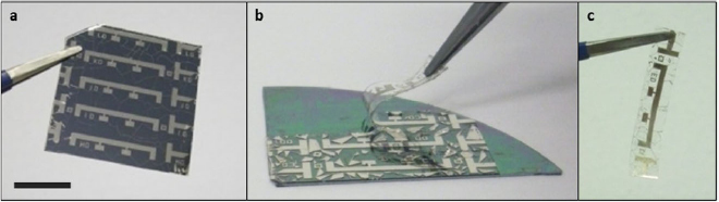
Figure 3. Peeling of GMR multilayers on PDMS from the handling wafer: (a) array of photopatterned ![$\left[{\rm Co}/{\rm Cu} \right]_{50}^{1{\rm st}}$](https://content.cld.iop.org/journals/0022-3727/53/8/083002/revision2/dab52cfieqn006.gif) multilayers on a PDMS coated silicon wafer (scale bar: 10 mm). (b) Peeling of an individual GMR element from the rigid silicon support by means of the anti-stick layer. (c) Photopatterned
multilayers on a PDMS coated silicon wafer (scale bar: 10 mm). (b) Peeling of an individual GMR element from the rigid silicon support by means of the anti-stick layer. (c) Photopatterned ![$\left[{\rm Co}/{\rm Cu} \right]_{50}^{1{\rm st}}$](https://content.cld.iop.org/journals/0022-3727/53/8/083002/revision2/dab52cfieqn007.gif) multilayer element on a free-standing PDMS membrane of 40 µm thickness. (c) Reprinted with permission from [40]. Copyright (2011) American Chemical Society.
multilayer element on a free-standing PDMS membrane of 40 µm thickness. (c) Reprinted with permission from [40]. Copyright (2011) American Chemical Society.
Download figure:
Standard image High-resolution imageFigure 4(a) shows the GMR ratio measured at room temperature for such multilayers on different substrates. The GMR ratio is obtained by the change of electrical resistance R(H) relative to the value at magnetic saturation Rsat: GMR = R(H) − Rsat/Rsat. Curves obtained from samples prepared in the same deposition run on a rigid silicon wafer without (SiOx) and with PDMS coating (PDMS/SiOx) are very similar. A maximum GMR value of more than 50% is obtained on both substrates, which is a typical value for Co/Cu based GMR multilayers [96]. Furthermore, the GMR characteristic does not change after the sample is peeled off the silicon wafer (PDMS). Hence, the magnetic sensing capabilities of GMR multilayer elements on free-standing rubber membranes are as good as on conventional rigid silicon substrates [40]. The absolute sensor resistances for the three cases, as given in the caption of figure 4, are also found to be very comparable.
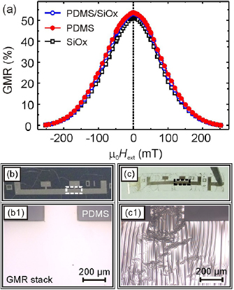
Figure 4. Characterization of GMR multilayers on PDMS: (a) GMR curves of ![$\left[{\rm Co}/{\rm Cu} \right]_{50}^{1{\rm st}}$](https://content.cld.iop.org/journals/0022-3727/53/8/083002/revision2/dab52cfieqn008.gif) elements grown on rigid silicon wafer (
elements grown on rigid silicon wafer ( ; R0 = 15.3 Ω), PDMS coated silicon wafer (
 ; R0 = 15.9 Ω) and free-standing PDMS membrane (
 ; R0 = 15.0 Ω). (b) and (c) Photographs (top) of the PDMS/SiOx and PDMS samples, respectively and optical micrographs (bottom) of the sections highlighted by the dashed squares. All scale bars: 200 µm. Reprinted with permission from [40]. Copyright (2011) American Chemical Society.
Download figure:
Standard image High-resolution imageAlthough the GMR performance of the devices on freestanding PDMS membranes and on PDMS-coated silicon wafers is similar, the morphology of the samples is found to be substantially different. Figures 4(b) and (c) shows photographs and optical microscopy close-ups of a GMR multilayer on top of the PDMS surface before and after the rubber was delaminated from the rigid substrate. When the rubber film is still attached to the silicon wafer, the metal film is smooth, which indicates low intrinsic stresses during the deposition of the GMR multilayers [104]. On the peeled rubber membrane, however, the formation of buckles is observed (bottom of figure 4(c)).
2.1. Thermally induced wrinkling
The observed wrinkling of the GMR layer upon peeling is caused by the curing of the spin-coated PDMS films at an elevated temperature during its fabrication. The thermal shrinkage of the cured rubber film upon cooling down is suppressed in the lateral directions by the rigid silicon wafer it is attached to. This suppression is due to a large mismatch of the thermal expansion coefficients α of the two materials (αPDMS = 9.6 × 10⁻⁴ K−1 versus αSi = 2.6 × 10⁻⁶ K−1). As a result, a significant part of the thermal contraction of the rubber is 'stored' by means of a compressive lateral stress arising inside the elastic PDMS film. This stress is maintained during the structuring and sputter deposition of the GMR layers and is not released until the sample is peeled from the rigid supporting wafer. Upon peeling, the rubber laterally contracts which causes wrinkling of the incompressible metal film [126]. This feature is referred to as thermally induced wrinkling [127]. The thermal contraction along one axis of the PDMS film for the applied temperature difference of ΔT = 70 K (from 90 °C down to room temperature), is about 7%. The shrinkage of the elastomeric support also revealed a self-healing effect [128] on GMR films that were broken during their fabrication, as distinct cracks could be closed upon peeling and the electric and magnetoresistive properties of the sensing elements could be fully restored.
Figure 5(a) shows a 3D confocal laser scanning microscopy of a GMR multilayer on a free-standing PDMS membrane. Although the thermally induced pre-strain leads to a laterally isotropic contraction of the rubber film, the wrinkles have a strong preference for a parallel alignment perpendicular to the patterned stripe structure (in figure 5(a), the sensor stripe lies in the horizontal axis). This is expected, as wrinkles generally tend to align perpendicular to structural defects or the edges of structured films [115, 129]. Furthermore, the specimens are peeled along the stripe structure, which favours the wrinkling perpendicular to it. The aligned wrinkling of the metal film, with the stress being relaxed along the sensor stripe, makes it more stiff in the orthogonal direction [130], which prevents the perpendicular stress relaxation and associated wrinkling in most regions. Instead, a slight bending across the GMR stripe could be observed on the peeled sensor elements.
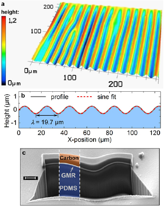
Figure 5. Thermally induced wrinkling on PDMS: wrinkled topography of GMR multilayer elements prepared on PDMS films after peel-off. (a) 3D confocal microscopy image showing the height profile. (b) Confocal line scan (gray) and sinusoidal fit (red) providing a mean wrinkle period λ of 19.7 µm. (c) SEM image of a FIB cut through the sample showing the deposited carbon protective layer for FIB cutting, the ![$\left[{\rm Co}/{\rm Cu} \right]_{50}^{1{\rm st}}$](https://content.cld.iop.org/journals/0022-3727/53/8/083002/revision2/dab52cfieqn012.gif) GMR layer and the PDMS substrate (scale bar: 2 µm). Adapted with permission from [40]. Copyright (2011) American Chemical Society.
GMR layer and the PDMS substrate (scale bar: 2 µm). Adapted with permission from [40]. Copyright (2011) American Chemical Society.
Download figure:
Standard image High-resolution imageWrinkling of hard films on soft membranes exhibits a characteristic wrinkling period, which depends on the mechanical properties of both materials and scales with the film thickness [115, 131]. The height profile of the soft GMR elements reveals a wrinkling period of λexp = 19.7 µm and a mean amplitude of about 0.45 µm (figure 5(b)). A FIB cut of the sample (figure 5(c)) discloses the wavy GMR film (indicated by the gray line) firmly attached to the bulky rubber (highlighted in blue). This suggests that the contact between the PDMS and the metal film is maintained throughout the wrinkle structure and no delamination occurs. On the one hand, a good adhesion is essential for the stable operation of thin film electronic devices on soft supports, especially regarding their long-term behaviour. Otherwise, delamination would occur and destroy the electrical and magnetic integrity of the functional layers over time. On the other hand, a theoretical model suggested by Bowden et al [115] can be applied in this case to calculate the period of the wrinkles formed for a thin incompressible metal film of thickness d on an elastomeric surface. Considering the total thickness of the GMR multilayer stack of 110 nm, the calculation predicts a value for the wrinkling period of λtheo ≈ 21.7 µm [40], which is in good agreement with the experimental value derived from the line scan in figure 5(b). The critical strain [132] for the occurrence of wrinkling in the investigated system is computed to be εc = 0.26‰.
2.2. Sensitivity enhancement
The magnetoresistive Co/Cu multilayers prepared in the first coupling maximum (i.e. ![$\left[{\rm Co}/{\rm Cu} \right]_{50}^{1{\rm st}}$](https://content.cld.iop.org/journals/0022-3727/53/8/083002/revision2/dab52cfieqn013.gif) ) are optimized in order to obtain a maximum GMR ratio and exhibit a saturation field of about 2.5 kOe (figure 4(a)). The respective GMR characteristic makes it a good choice to use as sensing elements for magnetic fields in the range of about 1 kOe. However, different applications demand different sensing capabilities that require specific features of the sensor response, like a linear characteristic or a high sensitivity to low magnetic field strengths. One example is the application of magnetic sensors in medical diagnostics or bio-analytic systems [103, 133–135], which requires reliable detection of magnetic fields in the range of 10 Oe and below.
) are optimized in order to obtain a maximum GMR ratio and exhibit a saturation field of about 2.5 kOe (figure 4(a)). The respective GMR characteristic makes it a good choice to use as sensing elements for magnetic fields in the range of about 1 kOe. However, different applications demand different sensing capabilities that require specific features of the sensor response, like a linear characteristic or a high sensitivity to low magnetic field strengths. One example is the application of magnetic sensors in medical diagnostics or bio-analytic systems [103, 133–135], which requires reliable detection of magnetic fields in the range of 10 Oe and below.
In order to qualify the described compliant magnetic sensor platform for a wider field of applications, four different systems of GMR multilayers were fabricated and compared on free-standing elastomer membranes, highlighting their unique magnetoelectric properties [136].
- Co/Cu multilayer in the first coupling maximum: Co(1)/[Cu(1.2)/Co(1)]50 →
![$\left[{\rm Co}/{\rm Cu} \right]_{50}^{1{\rm st}}$](data:image/png;base64,iVBORw0KGgoAAAANSUhEUgAAAAEAAAABCAQAAAC1HAwCAAAAC0lEQVR42mNkYAAAAAYAAjCB0C8AAAAASUVORK5CYII=)
- Py/Cu multilayers in the first coupling maximum: Py(1.9)/[Cu(0.9)/Py(1.9)]50 →
- Co/Cu multilayers in the second coupling maximum: Co(1)/[Cu(2.2)/Co(1)]30 →
- Py/Cu multilayers in the second coupling maximum: Py(1.5)/[Cu(2.3)/Py(1.5)]30 →
![$\left[{\rm Co}/{\rm Cu} \right]_{50}^{1{\rm st}}$](https://content.cld.iop.org/journals/0022-3727/53/8/083002/revision2/dab52cfieqn014.gif)
![$\left[{\rm Py}/{\rm Cu} \right]_{50}^{1{\rm st}}$](https://content.cld.iop.org/journals/0022-3727/53/8/083002/revision2/dab52cfieqn015.gif)
![$\left[{\rm Co}/{\rm Cu} \right]_{30}^{2{\rm nd}}$](https://content.cld.iop.org/journals/0022-3727/53/8/083002/revision2/dab52cfieqn016.gif)
![$\left[{\rm Py}/{\rm Cu} \right]_{30}^{2{\rm nd}}$](https://content.cld.iop.org/journals/0022-3727/53/8/083002/revision2/dab52cfieqn017.gif)
All thickness values are given in nm and Py denotes the soft magnetic permalloy (Ni81Fe19). In comparison to the previously presented ![$\left[{\rm Co}/{\rm Cu} \right]_{50}^{1{\rm st}}$](https://content.cld.iop.org/journals/0022-3727/53/8/083002/revision2/dab52cfieqn018.gif) multilayer, the adaption of the GMR stack includes two approaches to enhance the sensitivity to external magnetic fields, which are approved for rigid substrates [93]. On the one hand, the magnetically softer permalloy, that shows a different switching behaviour due to its reduced coercivity, is used as the ferromagnetic layers in
multilayer, the adaption of the GMR stack includes two approaches to enhance the sensitivity to external magnetic fields, which are approved for rigid substrates [93]. On the one hand, the magnetically softer permalloy, that shows a different switching behaviour due to its reduced coercivity, is used as the ferromagnetic layers in ![$\left[{\rm Py}/{\rm Cu} \right]_{50}^{1{\rm st}}$](https://content.cld.iop.org/journals/0022-3727/53/8/083002/revision2/dab52cfieqn019.gif) . On the other hand, the magnetic layers are coupled in the 2nd antiferromagnetic coupling maximum by increasing the thickness of the copper spacer layers in
. On the other hand, the magnetic layers are coupled in the 2nd antiferromagnetic coupling maximum by increasing the thickness of the copper spacer layers in ![$\left[{\rm Co}/{\rm Cu} \right]_{30}^{2{\rm nd}}$](https://content.cld.iop.org/journals/0022-3727/53/8/083002/revision2/dab52cfieqn020.gif) , which leads to a weaker interlayer exchange coupling between the ferromagnetic layers [125]. Both modifications allow the magnetic moments in the multilayers to align (i.e. the resistance to drop) at lower magnetic fields. The
, which leads to a weaker interlayer exchange coupling between the ferromagnetic layers [125]. Both modifications allow the magnetic moments in the multilayers to align (i.e. the resistance to drop) at lower magnetic fields. The ![$\left[{\rm Py}/{\rm Cu} \right]_{30}^{2{\rm nd}}$](https://content.cld.iop.org/journals/0022-3727/53/8/083002/revision2/dab52cfieqn021.gif) stack represents a combination of both approaches by preparing a Py/Cu multilayer coupled in the 2nd coupling maximum. As for the
stack represents a combination of both approaches by preparing a Py/Cu multilayer coupled in the 2nd coupling maximum. As for the ![$\left[{\rm Co}/{\rm Cu} \right]_{50}^{1{\rm st}}$](https://content.cld.iop.org/journals/0022-3727/53/8/083002/revision2/dab52cfieqn022.gif) GMR elements already presented above, the multilayers were lithographically structured on a PDMS film with thermally induced pre-strain and then peeled from the carrying wafer after preparation.
GMR elements already presented above, the multilayers were lithographically structured on a PDMS film with thermally induced pre-strain and then peeled from the carrying wafer after preparation.
For a comparison of their specific sensing capabilities, the four multilayer systems were characterized at room temperature, as shown in figure 6. Each layer stack was measured on the PDMS film before and after peeling and on a rigid SiOx wafer as a reference. In all four cases, the multilayer elements reveal a similar GMR performance on the elastomeric substrates, as on the rigid reference samples. As in the case of ![$\left[{\rm Co}/{\rm Cu} \right]_{50}^{1{\rm st}}$](https://content.cld.iop.org/journals/0022-3727/53/8/083002/revision2/dab52cfieqn023.gif) , the thermally induced wrinkling that occurs when the PDMS membranes are peeled has little influence on the GMR characteristic in the other three multilayer systems, which proves the applied fabrication technology suitable for a variety of magnetoresistive sensing elements. The data also includes the magnetic field dependent sensitivity of the different GMR multilayers derived from the measurements on free-standing PDMS membranes. The sensitivity S of the GMR elements is related to the slope of the GMR characteristic, according to S(H) = (dR(H)/dH)/R(H).
, the thermally induced wrinkling that occurs when the PDMS membranes are peeled has little influence on the GMR characteristic in the other three multilayer systems, which proves the applied fabrication technology suitable for a variety of magnetoresistive sensing elements. The data also includes the magnetic field dependent sensitivity of the different GMR multilayers derived from the measurements on free-standing PDMS membranes. The sensitivity S of the GMR elements is related to the slope of the GMR characteristic, according to S(H) = (dR(H)/dH)/R(H).

Figure 6. GMR multilayers with enhanced sensitivity on PDMS: magnetoelectric characterization of the four investigated GMR multilayer stacks: (a) ![$\left[{\rm Co}/{\rm Cu} \right]_{50}^{1{\rm st}}$](https://content.cld.iop.org/journals/0022-3727/53/8/083002/revision2/dab52cfieqn024.gif) . The GMR sensors are fabricated on different substrates: rigid SiOx wafer (
. The GMR sensors are fabricated on different substrates: rigid SiOx wafer ( ), PDMS coated SiOx wafer (
 ) and free-standing PDMS membrane (
 ). The field dependent sensitivity of the GMR sensors on free-standing PDMS membranes is also shown (
 ). The inset in (d) shows the same data zoomed in the low field range for better distinction. Reproduced from [136] with permission of The Royal Society of Chemistry.
Download figure:
Standard image High-resolution imageCompared to the ![$\left[{\rm Co}/{\rm Cu} \right]_{50}^{1{\rm st}}$](https://content.cld.iop.org/journals/0022-3727/53/8/083002/revision2/dab52cfieqn029.gif) system (figure 6(a)) the magnetically softer Py layers do not lead to an overall increased sensitivity, whereas the magnitude of the GMR ratio is only half as large (figure 6(b)). However, the sensitivity maximum is shifted to the low field range (i.e. from about 800 Oe in (a) to 80 Oe in (b)) and the GMR characteristic becomes more linear. Therefore, this layer system would be well suited for example for proximity sensors monitoring the distance to a permanent magnet, which typically generates fields of about 1 kOe in close vicinity. The
system (figure 6(a)) the magnetically softer Py layers do not lead to an overall increased sensitivity, whereas the magnitude of the GMR ratio is only half as large (figure 6(b)). However, the sensitivity maximum is shifted to the low field range (i.e. from about 800 Oe in (a) to 80 Oe in (b)) and the GMR characteristic becomes more linear. Therefore, this layer system would be well suited for example for proximity sensors monitoring the distance to a permanent magnet, which typically generates fields of about 1 kOe in close vicinity. The ![$\left[{\rm Co}/{\rm Cu} \right]_{30}^{2{\rm nd}}$](https://content.cld.iop.org/journals/0022-3727/53/8/083002/revision2/dab52cfieqn030.gif) multilayer reveals a narrow response curve without losing as much of the GMR effect (figure 6(c)), giving it an increased sensitivity compared to the multilayers prepared in the 1st coupling maximum. This system should be chosen, if a high signal for moderate fields up to 500 Oe is needed. The GMR curves obtained for the
multilayer reveals a narrow response curve without losing as much of the GMR effect (figure 6(c)), giving it an increased sensitivity compared to the multilayers prepared in the 1st coupling maximum. This system should be chosen, if a high signal for moderate fields up to 500 Oe is needed. The GMR curves obtained for the ![$\left[{\rm Py}/{\rm Cu} \right]_{30}^{2{\rm nd}}$](https://content.cld.iop.org/journals/0022-3727/53/8/083002/revision2/dab52cfieqn031.gif) multilayer are very narrow with a saturation field of about 50 Oe and exhibit a considerable resistance change of more than 13% (figure 6(d)). The sensitivity of these elements on free-standing PDMS reaches a remarkable value of 1.06%/Oe, which is almost 30 times larger than for the
multilayer are very narrow with a saturation field of about 50 Oe and exhibit a considerable resistance change of more than 13% (figure 6(d)). The sensitivity of these elements on free-standing PDMS reaches a remarkable value of 1.06%/Oe, which is almost 30 times larger than for the ![$\left[{\rm Co}/{\rm Cu} \right]_{50}^{1{\rm st}}$](https://content.cld.iop.org/journals/0022-3727/53/8/083002/revision2/dab52cfieqn032.gif) samples. Also, the maximum of the sensitivity is found at very low fields of only 8 Oe, making it the system of choice for the detection of small or weak magnetic objects [136], for example microscopic magnetic particles as they are used in biotechnology and medical applications [137, 138]. A unique feature that can be added by soft magnetoresistive sensors in this respect will be introduced in the next paragraph.
samples. Also, the maximum of the sensitivity is found at very low fields of only 8 Oe, making it the system of choice for the detection of small or weak magnetic objects [136], for example microscopic magnetic particles as they are used in biotechnology and medical applications [137, 138]. A unique feature that can be added by soft magnetoresistive sensors in this respect will be introduced in the next paragraph.
Table 2 summarizes the key parameters of the four GMR multilayer systems investigated in this study. The GMR sensor response can be further adapted to specific applications by altering its shape, by means of magnetic shape anisotropy [139] or adjusting its size to the magnetic objects that should be detected.
Table 2. Key parameters of GMR multilayers deposited on PDMS: denotation, GMR magnitude, maximum sensitivity and field of highest sensitivity for the four investigated GMR multilayer stacks, according to the data presented in figure 6.
| Multilayer: | ![$\left[{\rm Co}/{\rm Cu} \right]_{50}^{1{\rm st}}$](https://content.cld.iop.org/journals/0022-3727/53/8/083002/revision2/dab52cfieqn033.gif) |
![$\left[{\rm Py}/{\rm Cu} \right]_{50}^{1{\rm st}}$](https://content.cld.iop.org/journals/0022-3727/53/8/083002/revision2/dab52cfieqn034.gif) |
![$\left[{\rm Co}/{\rm Cu} \right]_{30}^{2{\rm nd}}$](https://content.cld.iop.org/journals/0022-3727/53/8/083002/revision2/dab52cfieqn035.gif) |
![$\left[{\rm Py}/{\rm Cu} \right]_{30}^{2{\rm nd}}$](https://content.cld.iop.org/journals/0022-3727/53/8/083002/revision2/dab52cfieqn036.gif) |
|---|---|---|---|---|
| Panel in figure 6: | a | b | c | d |
| GMR magnitudes | ||||
| On SiOx | 54.7% | 26.5% | 31.3% | 14.1% |
| On SiOx/PDMS: | 54% | 25.4% | 28.3% | 13.9% |
| On PDMS membrane: | 53.7% | 25.2% | 27.9% | 13.5% |
| Max. sensitivity Smax: (%/Oe) | 0.034 | 0.022 | 0.113 | 1.06 |
| Filed of Smax: (Oe) | 800 | 80 | 160 | 8 |
2.3. GMR sensors in circumferential geometry
Based on the magnetoresistive sensing elements with enhanced sensitivities, a conceptually new approach for the detection of magnetic objects flowing through a fluidic channel was introduced [136]. This detection scheme is facilitated by the unique mechanical properties of the prepared soft GMR sensor elements, which allow them to be reshaped on demand after their fabrication. It is demonstrated that using this approach the stray fields generated by the flowing magnetic objects can be detected virtually in all directions (isotropic sensitivity) [136], which is unique compared to conventional rigid sensors [83, 140].
Magnetic particles are widely used for diagnostic or therapeutic purposes in biology and medicine [103, 137, 138, 141, 142], implying the necessity of implementation of magnetic field sensors in complex biomedical systems. In this respect, magnetoresistive sensors, especially those relying on the GMR effect represent an efficient solution for the use in fluidic biodetection platforms due to their high sensitivity [143]. Planar [83, 144, 145] as well as rolled-up83 magnetic sensors have previously been incorporated into microfluidic channels enabling detection of magnetic particles. The fabrication of these magnetic sensors requires extensive lithographic processing and is therefore expensive and time consuming [103, 133]. In contrast, for the dynamically developing millifluidic approach [146–148], which implies the use of millimeter size objects, a sensor can be of larger size and its design can be simplified substantially [149]. In this case, cost effective solutions for a magnetic sensor with an attractive possibility to be easily integrated into a system and to be reused several times are of great advantage.
GMR elements on free-standing elastomeric membranes can attain the above mentioned requirements in an elegant way. The prepared GMR sensors combine the advantages of being flexible with the speed and performance of conventional magnetoresistive devices on rigid substrates [40]. Due to their compliant nature, they can be efficiently implemented in a millifluidic system by wrapping them tightly around the fluidic channel [136], as shown in figure 7(a). Given the imposed cylindrical symmetry, an isotropic sensitivity can be expected for detection of the stray fields of magnetic particles in a suspension [82] that flows through the tubing. This is a unique feature of flexible magnetic sensors compared to their rigid planar counterparts, which are able to detect only a component of the magnetic stray field, parallel to the sensor's plane, thus limiting the possibility for efficient and quantitative detection of small magnetic objects. In addition, the cylindrical symmetry of the wrapped sensors makes the detected signal less dependent on the position of a magnetic object inside the tubing, since the sensing element covers its entire circumference. Therefore, this approach can diminish the need of applying an external magnetic bias field to align the magnetic moment of the particles with the direction of maximum sensitivity of a conventional planar sensor. This feature is particularly interesting for a quantitative in-flow analysis of microscopic objects, which is nowadays predominantly realized by optical means [150, 151]. Advanced magnetic analysis in fluidic systems is based on the selective immobilization of magnetic objects at the sensor site and the subsequent magnetization or alignment of the stray fields [103, 133]. Finally, in combination with magnetic particles as biomarkers [138, 152], these compliant magnetic sensors can be considered as a new generation of biosensors for cells or even biomolecules [103, 133] evading many difficulties of traditional optical detection methods [153] like low speed, excitation, bulky and expensive equipment, biomolecular amplification and the need for transparent packaging. For the integration of circumferential magnetic sensorics into microfluidic systems, however, rolled-up nanotechnology should be considered [81]. The potential of the magnetic in-flow detection in flexible fluidic systems was demonstrated by Lin et al [51].
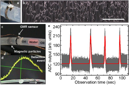
Figure 7. Detection of magnetic particles in a fluidic channel: (a) soft multilayer element of ![$\left[{\rm Py}/{\rm Cu} \right]_{{\rm 30}}^{{\rm 2nd}}$](https://content.cld.iop.org/journals/0022-3727/53/8/083002/revision2/dab52cfieqn037.gif) wrapped around the circumference of a Teflon tube and contacted using silver paste. (b) Optical microscopy image of the wrinkled sensor surface on a free-standing PDMS membrane. (scale bar: 1 mm) (c) Agglomerate of FeNdB particles suspended in oil and separated by coloured water droplets inside the tube approaching the wrapped GMR sensor. (d) Sensor signal on an oscilloscope (background) as the magnetic cluster is passing the multilayer element (foreground). (e) Several consecutive detection events of particles passing the soft GMR sensor without an alignment of their magnetic moments. The gray line shows the acquired data, the red line is included as a guide to the eye. Reproduced from [136] with permission of The Royal Society of Chemistry.
wrapped around the circumference of a Teflon tube and contacted using silver paste. (b) Optical microscopy image of the wrinkled sensor surface on a free-standing PDMS membrane. (scale bar: 1 mm) (c) Agglomerate of FeNdB particles suspended in oil and separated by coloured water droplets inside the tube approaching the wrapped GMR sensor. (d) Sensor signal on an oscilloscope (background) as the magnetic cluster is passing the multilayer element (foreground). (e) Several consecutive detection events of particles passing the soft GMR sensor without an alignment of their magnetic moments. The gray line shows the acquired data, the red line is included as a guide to the eye. Reproduced from [136] with permission of The Royal Society of Chemistry.
Download figure:
Standard image High-resolution imageTo realize the in-flow detection of magnetic particles using the soft GMR multilayer elements within the proposed detection approach, a simple millifluidic circuit was designed using a Teflon tube (inner diameter: 1.5 mm; outer diameter: 3.2 mm) [136]. Detection of magnetic particles typically requires a high sensitivity of the sensor to magnetic fields in the range of 10 Oe and below [81, 133, 144, 154–156]. As discussed above, because of their outstanding sensitivity to small magnetic fields, ![$\left[{\rm Py}/{\rm Cu} \right]_{30}^{2{\rm nd}}$](https://content.cld.iop.org/journals/0022-3727/53/8/083002/revision2/dab52cfieqn038.gif) multilayers are chosen for this task. A microscopic image of the GMR layer after peeling, showing its thermally induced wrinkling, is displayed in figure 7(b). Due to the flexibility of the prepared sensor elements it is possible to wrap the GMR film on the rubber membrane around the entire outer circumference of the millifluidic channel (figures 7(a) and (c)). No adhesive was used to attach the sensor to the tubing, which renders the detachment and re-use of individual elements possible. The fluidic circuit allows the flow of magnetic particles inside the tube towards the sensing element. The wrapped sensor was contacted for a two-probe measurement of the electrical resistance with a twisted pair of thin copper wires using conductive silver paste and connected to a self-made data acquisition hardware. The experiment was performed using commercially available Fe67Nd22B10 magnetic particles dispersed in a mineral oil. Sorbitane monooleate was added to reduce the wetting of the dispersion on the tube walls. When placed in a liquid, the magnetic particles quickly aggregate, forming macroscopic clusters with sizes of about 1 mm. These clusters were pumped into the fluidic channel. In order to separate neighboring clusters for detection, water droplets, colored by red ink, were injected into the channel as spacers (figure 7(c)). As the magnetic particles appear in close vicinity to the GMR detector the total resistance of the sensor element decreases, resulting in an easily detectable voltage change of the sensor's output (figure 7(d)). Several consecutive in-flow detection events are demonstrated in figure 7(e) by monitoring the time evolution of the sensor's output. The signal to noise ratio is about 13 dB, which allows detecting reliably the magnetic objects of interest and suggests that even smaller particles can be detected.
multilayers are chosen for this task. A microscopic image of the GMR layer after peeling, showing its thermally induced wrinkling, is displayed in figure 7(b). Due to the flexibility of the prepared sensor elements it is possible to wrap the GMR film on the rubber membrane around the entire outer circumference of the millifluidic channel (figures 7(a) and (c)). No adhesive was used to attach the sensor to the tubing, which renders the detachment and re-use of individual elements possible. The fluidic circuit allows the flow of magnetic particles inside the tube towards the sensing element. The wrapped sensor was contacted for a two-probe measurement of the electrical resistance with a twisted pair of thin copper wires using conductive silver paste and connected to a self-made data acquisition hardware. The experiment was performed using commercially available Fe67Nd22B10 magnetic particles dispersed in a mineral oil. Sorbitane monooleate was added to reduce the wetting of the dispersion on the tube walls. When placed in a liquid, the magnetic particles quickly aggregate, forming macroscopic clusters with sizes of about 1 mm. These clusters were pumped into the fluidic channel. In order to separate neighboring clusters for detection, water droplets, colored by red ink, were injected into the channel as spacers (figure 7(c)). As the magnetic particles appear in close vicinity to the GMR detector the total resistance of the sensor element decreases, resulting in an easily detectable voltage change of the sensor's output (figure 7(d)). Several consecutive in-flow detection events are demonstrated in figure 7(e) by monitoring the time evolution of the sensor's output. The signal to noise ratio is about 13 dB, which allows detecting reliably the magnetic objects of interest and suggests that even smaller particles can be detected.
The demonstrated concept for in-flow detection of magnetic particles in millifluidics using GMR sensors on PDMS membranes offers the following advantages compared to currently available solutions based on rigid magnetic sensors: (i) sensing of the magnetic stray fields in virtually all directions (isotropic sensitivity) without the need of an alignment of magnetic moments; (ii) simplicity of the sensor integration into a fluidic circuit; (iii) possibility of being reused on demand. Thus, the approach of flexible magnetic sensors wrapped around the circumference of a fluidic channel potentially opens exciting possibilities in the field of biology and chemistry, which are conceptually highlighted in figure 8. The displayed tubing may represent a timeline for a further development and miniaturization of the proposed technology, with the upper part (in-flow detection of magnetic particles) being realized on a proof-of-concept level, as described above. As a next step, the detection of biological objects, e.g. living cells with accumulated magnetic nanoparticles for magnetic-activated cell sorting (MACS) [152], is envisioned. With further miniaturization, the in-flow detection of magnetically tagged biomolecules [103, 133] seems feasible. However, on smaller scales, the implementation of rolled-up nanotechnology [157, 158] will be necessary for the sensor fabrication [159, 160] and integration into fluidic systems [161].
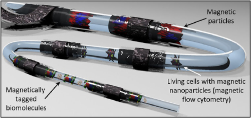
Figure 8. Concept of isotropic detection for biomedical applications: conceptual sketch demonstrating the potential of compliant magnetic sensors with isotropic sensitivity for the in-flow detection of magnetic objects of different sizes in fluidic channels for biomedical applications. Reproduced from [136] with permission of The Royal Society of Chemistry.
Download figure:
Standard image High-resolution image2.4. Stretchability test
The demonstrator presented above proved that the prepared GMR multilayer sensors are functional on curved surfaces. However, stretchable devices need to withstand tensile deformations as well. The thermally induced wrinkling of the GMR layer on soft membranes can help to protect the metallic film from cracking and breaking by smoothing out the buckles during uniaxial elongation of the rubber substrate [105]. Flat metal films without surface wrinkling are expected to withstand tensile strains of below 1% before breaking [162, 163]. In order to test their stretchability, wrinkled GMR multilayer elements were mounted into a computer controlled magnetoelectric characterization setup with in situ stretching capability. The electrical connection was realized by thin (0.1 mm) copper wires linked to the four contact pads using silver ink. The measurement routine includes applying an external uniaxial strain to the sample and, for each strain value, recording a GMR curve at room temperature.
Figure 9(a) shows GMR curves for increasing strains applied to the multilayer element. All curves, according to the color chart in the legend, are plotted in the graph and are congruent to each other. Hence, the GMR characteristic remains unaffected by applied tensile deformations up to 2.5%. The data obtained during the stretching experiment is summarized in figure 9(b), which displays the strain dependent GMR magnitude and absolute sample resistance of the sensor element during stretching. The curves reveal that the resistance remains constant for tensile strains below 1.7%. In this regime the sensor can be regarded as strain invariant, as its signal can be directly correlated to an in-plane magnetic field without compensating for a resistance change due to the tensile deformation. With further stretching, the resistance rises strongly until the electrical conduction across the element is lost beyond 2.6%. This increase of resistance at higher strains is attributed to the formation of microcracks, which lower the cross section of the conducting metal film. The most striking aspect of the stretching experiment is that, although its absolute resistance increases by a factor of about 5 during the elongation, the GMR ratio remains at a constant level. Hence, as demonstrated by the matching GMR curves, this suggests that even if the metallic film is partly damaged by the imposed tensile strain, the GMR effect is still present without major deterioration and the sample acts as a magnetic sensor element with the same performance as on rigid silicon substrates [136].

Figure 9. Stretching test of a wrinkled GMR sensor on PDMS membrane: (a) 27 GMR curves of a ![$\left[{\rm Co}/{\rm Cu} \right]_{50}^{1{\rm st}}$](https://content.cld.iop.org/journals/0022-3727/53/8/083002/revision2/dab52cfieqn039.gif) multilayer element measured at different applied strains (according to the legend) plus the reference curve recorded on a rigid SiOx wafer (
multilayer element measured at different applied strains (according to the legend) plus the reference curve recorded on a rigid SiOx wafer ( ). (b) GMR magnitude (
 ) and sample resistance (▪) in dependence of the imposed tensile strain. (c) 3D confocal microscopy images of the wrinkled GMR layer subjected to an increasing strain along the horizontal axis. Reprinted from [41], with the permission of AIP Publishing.
Download figure:
Standard image High-resolution imageTensile strains imposed on magnetic multilayers are actually expected to influence the GMR effect by reducing the spacer thickness and thus varying the interlayer exchange coupling [50, 164]. In the conducted stretching experiment however, no change of the GMR ratio upon stretching is found, which indicates that the tensile strain on the actual GMR multilayers is low due to the presence of the wrinkles. A set of confocal micrographs showing the wrinkled topography of the GMR film at zero strain and at two different stretched states is provided in panels (1–3) of figure 9(c). With increasing strain, the wrinkles become less pronounced and the entire metal film becomes smoother.
Cyclic loading experiments, which include measurements of resistance and the GMR effect during repeated consecutive stretching and relaxing periods, were also performed on these compliant GMR sensor elements, in order to demonstrate their elastic behaviour [40]. The sensors revealed low deviations of the GMR ratio (≈0.2%) and a stable resistance over 10 loading cycles between 0% and 1%, which makes them well-suited for magnetic sensor applications in environments where small dynamic deformations are required. These results represented the world's first elastically stretchable magnetic sensors.
2.5. Wrinkled GMR sensors with compliant meander patterns
Besides wrinkling, there are other approaches to impart compliant mechanical properties to functional systems based on rigid and brittle materials [4, 118, 165]. The stretchability of GMR multilayer elements could be improved by exploiting a meander structure, as an established technique for stretchable interconnects [109], which was prepared on PDMS membranes in a similar photolithographic lift-off process [128]. Figure 10 shows an applied meander pattern including four similar contact pads, which allow for reliable four-probe resistance and GMR characterizations of the fabricated magnetoresistive elements. Apart from the adapted geometry, the fabrication process is the same as for previously mentioned sensing elements, hence the thermally induces wrinkling is also present in the meander shaped sensors after peeling them from the handling support.
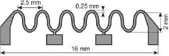
Figure 10. Meander sensor geometry: dimensioning of a compliant serpentine meander that was lithographically defined on elastomeric supports to enhance the stretchability of the GMR sensor elements. Reproduced with permission from [128].
Download figure:
Standard image High-resolution imageIn the stretchability test, shown in figure 11, these sensor structures reveal an enhanced resilience against tensile deformations [128]. The meander pattern represents a 2D spring that is compliant to uniaxial tensile deformations [165, 166]. Up to a deformation of 4%, the specimen reveals a GMR effect that is only gradually decreasing with strain (figure 11(a)). At 4.5% the GMR curve of the element shows an unstable behaviour (dashed line) before the contact is lost at 5% strain. The experimental data is again summarized in figure 11(b), where the GMR magnitude (red squares) and the absolute resistance (blue dots) are shown in dependence of the applied strain. This plot demonstrates the stable behaviour of the prepared GMR element up to about 3.5%. At this point, the GMR effect is reduced by less than 5% (absolute value) and the resistance increased by about 45%. It is expected that this strain denotes the point of reversible magneto-electric behaviour, where the GMR ratio is maintained also for mechanical unloading and reloading of the sensing element.
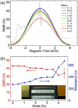
Figure 11. Stretchability test of the meander shaped GMR sensors: (a) GMR curves for different strains. (b) GMR magnitude ( ) and element resistance (
 ) in dependence of tensile strain. The inset shows the fixture of the specimen in the stretching apparatus. Reproduced with permission from [128].
Download figure:
Standard image High-resolution imageBeyond 3.5% the resistance starts to increase more substantially, which defines the upper limit of the stretchability at about 4.5% compared to the 2.5% reached using a simple stripe geometry [40, 136]. As the GMR nanomembrane, in addition to the structured meander pattern, exhibits also a wrinkled surface, due to the thermally induced pre-strain, a combination of both strategies accounts for the enhanced compliance of these GMR elements. Furthermore, another advantage of using meander-shaped sensors is an increased resistance, which is beneficial from the signal acquisition point of view.
3. Stretchable spin valves
Besides multilayers, also other GMR systems are known, which may provide superior performance, in particular aspects that are vital to specific application fields [93]. Spin valves (SV) exhibit a sensitivity that exceeds the values of ![$\left[{\rm Py}/{\rm Cu} \right]_{30}^{2{\rm nd}}$](https://content.cld.iop.org/journals/0022-3727/53/8/083002/revision2/dab52cfieqn044.gif) or other GMR multilayer systems [101]. This makes them particularly interesting for many applications, where the detection of small magnetic fields is required. Hence, a mechanical compliance of spin valves, in terms of stretchable magnetoelectronics, is highly promising for wearable [39, 167] and implantable [18, 77] electronics as well as for advanced bio-medical systems [32] to be equipped with magnetic functionalities. Most of these applications also require higher stretchabilities of the functional components to be integrated. Both aspects, increase of magnetic sensitivity and stretchability, have been addressed by the development of stretchable spin valves, which utilize a unique stretching mechanism relying on specific morphologic features [21].
or other GMR multilayer systems [101]. This makes them particularly interesting for many applications, where the detection of small magnetic fields is required. Hence, a mechanical compliance of spin valves, in terms of stretchable magnetoelectronics, is highly promising for wearable [39, 167] and implantable [18, 77] electronics as well as for advanced bio-medical systems [32] to be equipped with magnetic functionalities. Most of these applications also require higher stretchabilities of the functional components to be integrated. Both aspects, increase of magnetic sensitivity and stretchability, have been addressed by the development of stretchable spin valves, which utilize a unique stretching mechanism relying on specific morphologic features [21].
3.1. Random wrinkles and periodic fracture
The fabrication process of stretchable SVs was conducted similar to the stretchable GMR multilayers discussed above, as outlined in figure 12, using the approved 4-pin stripe pattern. The deposited magnetic layer stack of Ta(2)/Ir19Mn81(5)/[Ni81Fe19(4)/Co90Fe10(1)]/Cu(1.8)/[Co90Fe10(1)/Ni81Fe19(4)]/Ta(4) resembles an in-plane IrMn-based top-pinned symmetric SV. The entire deposition was done in the presence of a constant in-plane magnetic field of ≈1 kOe, in order to induce an antiferromagnetic order into the IrMn pinning layer and thus define the direction of the exchange bias (EB). This is necessary, since a conventional field cooling procedure is not possible on polymeric substrates, due to the high temperatures involved. If not stated differently, the EB direction was chosen to be perpendicular to the long axis of the patterned sensor stripe (cross-pinned configuration). In figure 12, emphasis is given to the morphologic transitions occurring on the sensor surface during the fabrication flow, which plays a key role for the enhanced stretchability in this case.

Figure 12. Morphologic transitions during the preparation of stretchable spin valves: the top right part conceptually shows the PDMS film on SiOx wafer as the substrate and the layer composition of the spin valve stack. After deposition, the SV film is randomly wrinkled, as shown in the top right micrograph. Peeling the sensor element from the supporting wafer leads to the formation of a periodic fracture pattern (bottom right), which acts as a template for a compliant meander pattern that evolves upon stretching (bottom left). The central part shows photographs of a prepared SV element (left) that can be distorted (center) or stretched (right). [21] John Wiley & Sons. Copyright © 2012 WILEY-VCH Verlag GmbH & Co. KGaA, Weinheim.
Download figure:
Standard image High-resolution imageUnder the used sputter conditions, the bottom 5 nm thick Ta seed layer grows with a strong compressive stress. This stress relaxes into the soft rubber substrate, forming a pattern of randomly aligned micro wrinkles [104]. Hence, the subsequent spin valve stack is deposited onto this wrinkled template in the same process, without interrupting the vacuum. An additional pattern of parallel trenches (periodic fracture) is induced in the SV film by the peeling process. Upon stretching, a pronounced grating of microcracks occurs, which resembles the pattern of the trenches.
AFM measurements on the SV layer stack grown on PDMS, provided in figure 13, reveal the details of the two morphologic key-features present in the as-prepared sensing elements. The random wrinkling of the sputtered SV stack is clearly observed in figure 13(a), when the rubber membrane is still attached to the handling wafer (period: 1.4 µm and amplitude: ≈160 nm). A similar image recorded after peeling the PDMS membrane with the sensor along the stripe direction is given in figure 13(b), showing the parallel trenches, which are oriented along the short axis of the sensor stripe with a periodicity of 13.9 ± 4.6 µm. A periodic fracture of the sensor film upon peeling was not observed in the previous case of GMR multilayers prepared in the same way [40, 128, 136]. Instead, these multilayers did exhibit a pronounced parallel wrinkling upon peeling, which is in contrast to the observed random wrinkling of the Ta seed layer in the case of the SV stack. The parallel wrinkling in GMR multilayers was assigned to a thermally induced stress in the PDMS film [40]. Although the profile of the periodic fracture differs from the sinusoidal shape of the wrinkling in GMR multilayers, as shown by the line scan in figure 13(c), its orientation is the same and the periodicity could be related to a theoretical prediction based on the same model [21]. Hence, the same physical origin could be expected, which was supported by FIB/SEM investigations of the parallel trenches.
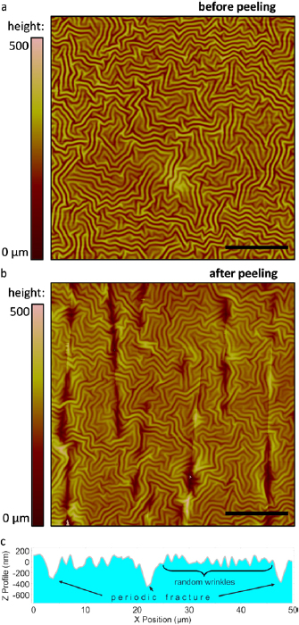
Figure 13. AFM investigations of random wrinkles and periodic fracture: (a) and (b) AFM measurements of the sensor film before and after peeling, respectively All scale bars: 20 µm. (c) Line profile extracted from (b) showing both morphologic features. [21] John Wiley & Sons. Copyright © 2012 WILEY-VCH Verlag GmbH & Co. KGaA, Weinheim.
Download figure:
Standard image High-resolution image3.2. GMR characterization of stretchable spin valves
The magneto-electrical characterization of the spin valve elements on rubber membranes at room temperature (red dots), in comparison with the performance of reference samples on rigid silicon substrates fabricated in the same deposition run (black squares), is presented in figure 14. The GMR curves consists of two sub-loops characteristic for the magnetization reversal of the magnetic free (at small fields) and pinned (shifted to higher fields due to the EB effect) layers. In general, the GMR characteristics on the soft supports show less sharp switching behaviour compared to their rigid counterparts. This is attributed to the pronounced randomly wrinkled morphology of the spin valve films, which leads to local fluctuations of the actual in-plane magnetic field component from a homogeneously applied field, due to film tilting. Accordingly, different parts of the magnetic layers may switch at slightly different external field, giving rise to more eroded GMR curves of the entire sensor element.
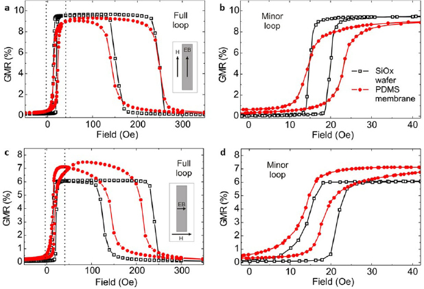
Figure 14. GMR characterization of the spin valves: GMR curves of the prepared spin valve elements on free-standing PDMS membranes ( ) and on a rigid SiOx wafer (
 ). Major loop (a) and minor loop (b) measurement for exchange bias set parallel to the long axis of the sensor stripe, as indicated in the inset. (c) and (d) Respective loops for exchange bias set perpendicular to the sensor stripe (cross-pinned configuration) as indicated in the inset. [21] John Wiley & Sons. Copyright © 2012 WILEY-VCH Verlag GmbH & Co. KGaA, Weinheim.
Download figure:
Standard image High-resolution imageFigure 14(a) shows the field dependent GMR ratio measured for the SV stacks with the EB direction set parallel to the sensor stripe (see inset). A maximum GMR value of more than 9% is obtained on both substrates. Furthermore, the GMR characteristics are comparable, which accounts for the good performance of the stretchable SV samples on rubber despite the strongly corrugated topography. Because spin valve elements are used for low field applications, its working region is limited to the switching region on the free (sensing) layer (i.e. between the two dotted lines). The corresponding GMR curves of only the free layer (minor loop characterization) is separately shown for both substrates in figure 14(b). Although the maximum GMR ratio of the SV stacks is smaller than for GMR multilayers, a sensitivity of 1.4%/Oe at low fields of 12 Oe is achieved on PDMS, which is superior to the stretchable sensitivity-optimized ![$\left[{\rm Py}/{\rm Cu} \right]_{30}^{2{\rm nd}}$](https://content.cld.iop.org/journals/0022-3727/53/8/083002/revision2/dab52cfieqn047.gif) multilayers [136].
multilayers [136].
Figures 14(c) and (d) provides similar data for SV sensors with the EB set perpendicular to the lithographically defined sensor geometry (cross-pinning). For both pinning directions, the external magnetic field for the magneto-electronic characterization is applied along the pinning axis, as this defines the sensitive direction of the SV device. Interestingly, an enhanced GMR magnitude is observed for cross-pinned sensors on a PDMS substrate, compared to its rigid silicon counterpart in this case, which was attributed to a realignment of the shape anisotropy induced by the present periodic fracture pattern perpendicular to the structured sensor stripe. However, also in this case, the GMR characteristics on both substrates are comparable to a certain extent. This data proved that spin vales can be prepared on free-standing rubber membranes as well, with similar sensing performance as on conventional rigid substrates.
3.3. Stretching of spin valves
A similar measurement scheme as for the GMR multilayers was conducted to study in situ the magnetoelectric behaviour of the free-standing PDMS membranes with patterned SV sensors under tensile deformation [21]. This study was carried out on cross-pinned sensor elements, as the stretching is possible perpendicular to the applied field and along the sensor stripe only. Furthermore, this configuration allows reducing the hysteresis of the free layer [168]. However, as the direction of the EB is defined solely by magnetic means, it is not expected to significantly influence the mechanical stretchability of the prepared sensors. GMR curves of the full range and minor loop obtained at different tensile strains are shown in figures 15(a) and (b), respectively. Remarkably, the characteristic shape of the GMR curve as well as the GMR magnitude remains similar up to high tensile strains of 29%. In figure 15(c), the GMR magnitude and the absolute sample resistance in magnetic saturation are displayed in dependence of the applied strain. For small deformations below 2%, there is a slight increase in both values. Even though the resistance of the SV element increases strongly while the sample is expanded to higher strains, the GMR magnitude changes only very gradually, until the electrical conduction is lost beyond 29%. With increasing strain, the minor loop becomes more sheared indicating a decrease of the sensitivity. Sensitivity values are obtained by averaging the slope of the ascending and descending branches of the minor loop. Furthermore, it is apparent that the hysteresis loops become significantly broader with rising strain. Both properties are plotted in dependence of the applied strain in figure 15(d). The apparent variations in the GMR characteristics upon stretching could be related to the respective morphologic transitions of the SV nanomembrane [21], which were revealed by detailed microscopic investigations.
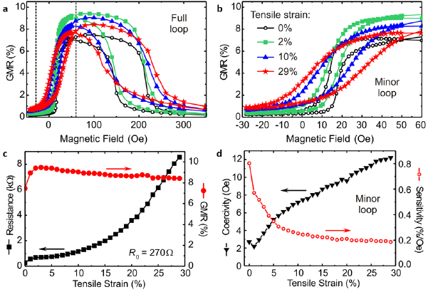
Figure 15. Stretchability of spin valve sensor elements: major loop (a) and minor loop (b) GMR curves at different applied strains according to the legend given in (b). (c) Magnitude of the GMR effect ( ) and absolute sample resistance (▪) in dependence of tensile strain up to the point where the electrical contact is lost. (d) Sensitivity of the SV element (
 ) and coercivity of the free layer (▼) over the applied tensile strain. [21] John Wiley & Sons. Copyright © 2012 WILEY-VCH Verlag GmbH & Co. KGaA, Weinheim.
Download figure:
Standard image High-resolution image3.4. Microcrack formation
The enhanced stretchability of the prepared SV elements, compared to the GMR multilayer based sensors [40, 128, 136], are accommodated by a distinct microcrack pattern occurring in the magnetic nanomembrane. Figures 16(a)–(c) shows a series of optical micrographs of the same area on the SV film at different applied strains along the horizontal axis (0%, 5%, and 20% respectively). These pictures demonstrate, that the parallel trenches, which are formed upon peeling the soft SV elements with thermally induced pre-strain from the handling support, evolve into open gaps as the rubber substrate underneath is expanded. In this respect, the trenches act as pre-determined fracturing sites for the formation of a compliant crack pattern. This microcrack formation gives rise to a meander-like structure that maintains a network of connected slaps along the surface which can facilitate high tensile strains [109]. Arrows in panel c indicate a conductive pathway across the highly stretched sensor surface. Random micro fracture of thin and flat metal films on elastomeric substrates is a well-established approach to generate highly compliant interconnects and surface electrodes for stretchable electronic platforms [4, 106]. Figures 16(d) and (e) show the topography of the relaxed and stretched SV film, respectively, obtained by confocal laser scanning microscopy. The way a thin film behaves upon compressive deformation on an elastomeric substrate, in particular concerning the formation of cracks, strongly depends on its ductile properties [15]. The different morphology that results from the release of the thermally induced pre-strain upon peeling compared to the observations on GMR multilayers above were attributed mainly to the presence of the brittle IrMn layer. In contrast to the materials present in the multilayers, which all exhibit a good ductility, the IrMn may cause the SV film to crack rather than to wrinkle upon compression. The apparent development of buckles perpendicular to the emerging gaps with rising strain originates from the Poisson's contraction of the elastomeric support [169, 170].

Figure 16. Formation of a compliant microcrack pattern upon stretching: (a-c) Optical micrographs of the sensor surface at 0%, 5% and 20% tensile strains, respectively. Indicated in (a) are the directions of the applied strain and magnetic field. A conductive pathway though the expanded microcrack pattern is indicated in (c). (d) and (e) 3D confocal laser scanning images showing the topography of the relaxed and stretched SV film, respectively. [21] John Wiley & Sons. Copyright © 2012 WILEY-VCH Verlag GmbH & Co. KGaA, Weinheim.
Download figure:
Standard image High-resolution imageIn order to reveal the nature of the microcrack pattern in more detail, an SEM study of the spin valve layer on the PDMS film was performed [21]. Figure 17 shows SEM images of the stretched SV sensor element including a cross-sectional view of one microcrack obtained through FIB milling. First of all, the micrographs show the good adhesion of the wrinkled SV layer to the elastic PDMS membrane underneath, which is an important factor for the high stretchability of the presented sensor elements. Hence, delamination and slipping of the sensor layer upon stretching can be excluded as the main mechanism during the elongation of the underlying PDMS membrane. It is clearly visible, that the random wrinkles from the Ta layer deposition are still present at high strains. Thus, the actual stress on the sensor layer slabs is assumed to be low and most of the strain is accommodated by the broadened microcracks. The deposition induced random wrinkling supports the accommodation of strain at the sites that bridge the different slabs between two opening gaps. Also visible are the perpendicular buckles from the Poisson contraction, which may also contribute to the perpetuation of conductive paths at higher strains. It was concluded that a smart interplay between periodic fracture and random wrinkling allows for the high stretchability achieved in the presented SV sensor elements.
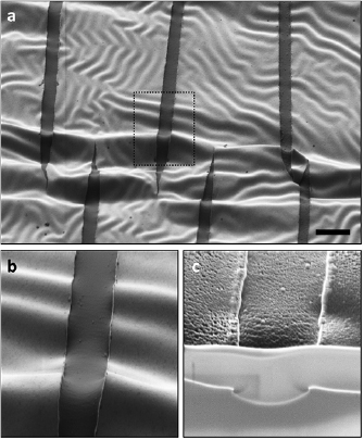
Figure 17. SEM/FIB investigation of the stretched spin valve: SEM images of (a) and (b) the stretched sensor surface and (c) a FIB cut through a periodic fracture site. Stretching was done along the horizontal axis by about 20%. Scale bar: 5 µm. [21] John Wiley & Sons. Copyright © 2012 WILEY-VCH Verlag GmbH & Co. KGaA, Weinheim.
Download figure:
Standard image High-resolution imageFor flat metallic films on elastomeric substrates, the number of cracks is expected to increase with applied tensile strain [169, 171]. In the present case, however, the initial number of cracks is predetermined by the period of the parallel trenches upon peeling. It can be assumed that initially, the number of periodic fractures is larger than the number of cracks necessary to accommodate the tensile deformation. Therefore, the number of cracks is not increasing for low and medium strains (figures 16(a) and (b)), even if the adhesion to the rubber is maintained and no slipping occurs. For higher strains, the number of necessary cracks eventually exceeds the number of initial periodic trenches and additional cracks may be formed (figure 16(c)). In any case, the first elongation creates the microcrack pattern and defines the absolute resistance of the sensor element, which is maintained for lower strains. As the geometry and orientation of the individual slabs does hardly change upon stretching, a stable GMR effect is observed as long as the electrical connection along the sensor film is maintained.
The induced periodic fracture of the sensor film not only allows for a high stretchability, but is also responsible for transitions in its GMR characteristic, which were highlighted in figure 15. The induced microcracks create perpendicular elongated slabs (figures 16(a)–(c)), which cause the shape anisotropy to realign along their long axis, rather than along the lithographically defined sensor stripe (i.e. parallel to the EB in case of the investigated cross-pinned configuration). This establishes a favourable uniaxial anisotropy with aligned magnetic moments leading to the observed early increase in the GMR magnitude (figure 15(c)). The effect of the relative alignment of shape anisotropy and exchange bias is also apparent from the data presented in figures 14(a) and (c), where on the rigid substrate the GMR magnitude is significantly higher for the parallel configuration. Since the gaps are opening already at low strains on the rubber substrate, due to the pre-determined periodic fracture, the transition of the shape anisotropy is completed at about 2% of tensile strain, which is enough to overcome the thermally induced pre-strain and open up the trenches into the periodic microcrack pattern.
Other variations in the GMR characteristics upon stretching could be attributed to the statistical distribution of the slab width or the occurrence of the perpendicular buckles from the Poisson contraction [21].
3.5. Cyclic loading
In order to test the elasticity and long-term reliability of these sensor elements, extensive cyclic loading experiments have been performed [21], which involve repeated uniaxial deformations between 5% and 10% strain. Before cycling, an initial loading step to 15% was applied to the as-prepared sample to induce the microcrack pattern as described above. The result of the cyclic loading experiment is shown in figure 18, where the GMR magnitude and resistance at the two strain reversal points is plotted in dependence of cycle number. The data shows similar GMR and resistance values at both strain states. Furthermore, no fatigue is observed, as all parameters remain at a constant level over several hundred loading cycles. For more than 500 cycles the data starts to scatter progressively, which could be attributed to electrical contact issues, rather than to a failure of the sensor element itself. Reliable electrical contacting of stretchable electronic devices, for tensile deformations of several tens of percent and above, remains a challenging task. Fully relaxing the SV elements back to 0% strain during cyclic loading appeared to induce significant fatigue in the sensor layer, which was attributed to internal friction of opposing edges of the apparent microcracks as they are closing upon each relaxation. However, the otherwise stable behaviour of the prepared SV elements suggests that the number and length of microcracks, created by the initial loading cycle is not changed during this experiment and renders the fabricated elements to be suitable as elastic and highly sensitive magnetoresistive sensors, if repeated relaxation to 0% strain is avoided.

Figure 18. Cyclic loading of stretchable spin valves: cycling interval: [5..10]%, with initial loading to 15% strain. Displayed are the GMR magnitude  and sample resistance
  at the minimum (filled symbols) and maximum (open symbols) strain over the number of loading cycles. Error bars represent the standard deviations of resistance values at magnetic saturation and GMR values on the plateau between the two hysteresis loops. [21] John Wiley & Sons. Copyright © 2012 WILEY-VCH Verlag GmbH & Co. KGaA, Weinheim.
Download figure:
Standard image High-resolution image3.6. Stretchable spin valves without microcrack formation
Recently, Li et al introduced dual spin valve ribbons prepared onto mechanically pre-stretched PDMS membranes that can accommodate high tensile deformations by means of wrinkling, without relying on cracks [172].
Figure 19(a) shows the deposited dual spin valve layer stack, which exhibits a symmetric core structure with a free magnetic layer (FeCo(1)/FeNi(6)/FeCo(1)) sandwiched between two pinned layers (FeCo(5)) which are exchange biased by two separate antiferromagnetic layers (IrMn(10)). Besides increasing the GMR effect of spin valves by enabling spin dependent scattering on both sides of the free layer, such a symmetric layer system may be beneficial for stretchable magnetoelectronics in particular, as the key functional part of the layer stack (i.e. the interfaces between the free layer and the adjacent non-magnetic Cu(3) spacers) is situated close to the neutral mechanical plane [173], which prevents in these layers the generation of large bending strains associated with wrinkling.

Figure 19. Wrinkled dual spin valve ribbons on pre-stretched PDMS: (a) the deposited layer stack of the dual spin valve (not drawn to scale). (b) Experimental setup configuration for the sample fabrication. (c) A schematic illustration of the as-fabricated SVR sample after releasing the tensile pre-strain. (d) Optical image of the SVR fabricated with a pre-strain of 30%. (e) The surface topography and (f) a cross-sectional line scan extracted along the red dashed line obtained by AFM (red dots: measured results, black line: sinusoidal fitting). Reprinted with permission from [172]. Copyright (2016) American Chemical Society.
Download figure:
Standard image High-resolution imageThe sensor fabrication scheme is shown in figure 19(b). The applied uniaxial pre-strains in the PDMS substrate of 30% and 50% lead to severe wrinkling of the spin valve layer stack upon its release. At the same time, a spin valve ribbon (SVR) pattern defined by a shadow mask, with 100 µm wide stripes aligned along the pre-strain direction and separated by 200 µm wide gaps effectively prevents the sensing layer from being torn apart by the severe lateral expansion perpendicular to the pre-strain direction due to the Poisson effect. A DC magnetic field perpendicular to the ribbon pattern during the deposition process defines the exchange bias direction in this work as well. The result are highly compliant SVRs that can accommodate lateral deformations in both directions: along the ribbons by means of parallel wrinkling and across the ribbons by expansion and contraction of the softer regions in between, as illustrated in figure 19(c).
The corrugated surface of the SVR fabricated with 30% pre-strain are further investigated in figures 19(d)–(f) by optical microscopy and AFM, respectively, revealing a sinusoidal topography with a periodicity of 7.66 µm and an amplitude of 1.42 µm. In case of 50% pre-strain, 8.22 and 1.75 µm are obtained, respectively [172]. Both wavelengths values agree well with the theoretically predicted wrinkling period for this system of 7.96 µm derived via the previously applied model suggested by N. Bowden et al [115].
GMR characteristics of the SVRs prepared with 0%, 30% and 50% pre-strain using in-plane magnetic fields applied perpendicular to the long axis of the ribbons are presented in figures 20(a)–(c), respectively. The curves show the typical shape of a dual spin valve which is attributed to the magnetization configurations of the three magnetic layers, as indicated in figure 20(a). Although the characteristics for the wrinkled SVRs slightly differ from the one on PDMS prepared without pre-strain, the magnetoresistive behaviour is similar and high GMR ratios can be obtained. Furthermore, the curves from the wrinkled SVRs hardly change with strains of 25% applied along the ribbon direction, accounting for the stretchability of these soft GMR sensing elements.
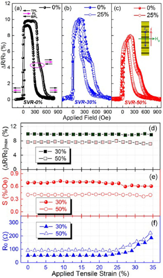
Figure 20. Stretching experiment for wrinkled spin valve ribbons: GMR characteristics of SVR (a) on PDMS without applied pre-strain (the magnetic configuration at the four distinct resistive states of the spin valve is indicated by arrows from top to bottom: top pinned layer-TPL, free layer-FL, and bottom pined layer-BPL), (b) with 30% pre-strain at 0 ( ) and 25% (
 ) applied tensile strain and (c) with 50% with pre-strain at 0 (
 ) and 25% (
 ) applied tensile strain. Inset in (c) indicates the directions of wrinkles, current, applied strain and magnetic field for these experiments. The dependence of (d) the GMR ratio (squares), (e) the magnetic field sensitivity (circles) and (f) the zero-field resistance (triangles) on the tensile strain applied along the ribbons is plotted for SVR with pre-strains of 30% (solid symbols) and 50% (open symbols), respectively. Reprinted with permission from [172]. Copyright (2016) American Chemical Society.
Download figure:
Standard image High-resolution imageThe strain dependences of the GMR ratio, the sensitivity as well as the zero-field sensor resistance for the SVR, with 30% and 50% pre-strain, are presented in figures 20(d)–(f), respectively. While the former two parameters remain constant for applied tensile strains of up to 35%, in both cases, the sensor resistance shows an increase for applied strains above 25%. Since the onset of the rising resistance is very similar for both SVR types prepared with highly different pre-strains, this deviation from the fully strain invariant behaviour may be attributed to a destabilization of contacts, rather than a damaging of the sensor element itself.
In order to test the long term stability, severe cyclic loading was performed on a SVR prepared with 30% pre-strain, as depicted in figure 21. The experiment involves 500 stretching cycles to a peak strain of 10%, followed by another 500 stretching cycles up to 20%, while the SVR is fully relaxed back to 0 strain in each cycle. The peak strain in this experiment is chosen well below the pre-strain during the fabrication. The three key parameters of GMR ratio, sensitivity and zero-field resistance are plotted over the cycle number in figures 21(a)–(c), respectively. Apparently the sensing element remains remarkably stable in all three parameters over both phases of cyclic loading. More precisely, for those parameters standard deviations of 1.4%, 2.6%, and 5.5% as well as 2.0%, 3.5%, and 6.4% are obtained for the two phases of cyclic loading to 10% and 20% tensile strain, respectively, accounting for their outstanding strain invariant properties and the lack of crack formation. A distinct role is also attributed to the ratio of SVR width and separation in order to further prevent cracking induced by the Poisson effect [172].
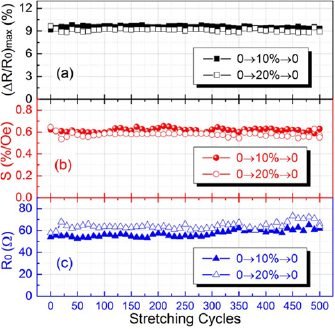
Figure 21. Cyclic loading of wrinkled spin valve ribbons: (a) GMR ratio (squares), (b) magnetic field sensitivity (circles) and (c) zero-field resistance (triangles) during the cyclic loading of a SVR prepared with 30% pre-strain to 10% (solid symbols) and 20% (open symbols), respectively. The GMR curves were recorded every 10 stretching cycles at the maximum strain state. The test with 20% peak strain was performed following the test with 500 loading cycles to 10% on the same piece of sample. Reprinted with permission from [172]. Copyright (2016) American Chemical Society.
Download figure:
Standard image High-resolution image4. Elastic GMR sensors via direct transfer printing
All approaches to fabricate stretchable magnetoelectronics described so far rely on the direct deposition and lithographic structuring of magnetoresistive thin films onto pre-strained elastomeric membranes [21, 40, 128, 136]. However, this method is associated with severe process limitations, preventing significant advances in performance and level of complexity and thus, restricting the applicability of the technology. First of all, the photolithographic structuring on the PDMS surface is challenging for feature sizes well below 100 µm [128] and multiple patterning steps, which are absolutely necessary for the integration of magnetoelectronic components into multifunctional stretchable electronic systems, can hardly be realized on PDMS reliably. Another crucial drawback is related to the limited stretchability of the functional elements relying on wrinkling due to thermally induced pre-strain. In fact, stretchabilities of a few percent only can be achieved in this way, unless cracking of the sensing layer is permitted. However, stretching due to crack formation is applicable only for thin film elements that are much larger than the cracks and hence, this approach contradicts the device miniaturization, which is highly relevant especially for the integration into wearable navigation and orientation systems, bio-medical systems [134, 135] or for the fine mapping of inhomogeneous magnetic fields and textures. Other application fields like smart skins [30, 39], functional medical implants [32, 77] and soft robotics [78, 174], require stretchabilities of electronic components in the order of 20% or more for useful integration. Further process limitations are related to the thermal and chemical conditions the polymeric substrate can endure during the fabrication of the magnetoelectronic system. These severe limitations call for a novel fabrication strategy of stretchable magnetoelectronic devices that allows for smaller structures and supports mechanically induced pre-strain.
Inspired by transfer printing techniques [175], a single step transfer printing process was developed for the fabrication of stretchable magnetic sensorics [176]. It allows preparing miniaturized and complex GMR systems on common rigid (donor) substrates, which are then directly transferred onto the elastomeric receiving substrate, without requiring micropatterned stamps, as for conventional transfer printing methods. With the preparation of entire magnetoelectric sensor systems or arrays including wiring and contact structures on silicon wafer substrates, the full potential of state-of-the-art microfabrication methods and thin film technologies can be exploited to reach a level of complexity that is not met when the magnetic layer stack is directly deposited onto elastomeric membranes. One of the key advantages is that the receiving PDMS substrate can be pre-stretched mechanically during the transfer process, which results in higher wrinkling amplitudes compared to the thermally pre-strained case [115, 177]. This is beneficial to achieve higher stretchabilities without inducing cracks in the functional magnetic layer. Another advantage of this approach is that the direction of the pre-strain can be controlled in order to either prepare systems that are compliant along one defined axis or even achieve biaxial stretchability [127]. Additionally, the advanced microfabrication potential allows for the combination with compliant meander geometries [109, 165] and fractal designs [178].
4.1. The direct transfer printing process
Figures 22(a)–(h) shows the process flow of the developed direct transfer method for GMR multilayer sensor elements. One of the key aspects is a sacrificial layer on top of the donor substrate (figure 22(a)), which facilitates the preparation of GMR sensor systems on its surface. For this purpose, Ca2+ metal cross-linked poly(acrylic acid) (PAA) with a total thickness of only 80 nm was chosen, fulfilling all crucial requirements for the sacrificial layer [179]. The resultant donor surface provides a very small roughness of below 1 nm and, together with its excellent chemical inertness and temperature stability, allows using the entire spectrum of multiple lithographic patterning and thin film preparation techniques to prepare sophisticated GMR sensoric systems. Another crucial issue is the good adhesion of the prepared sensor structures to the receiving elastomeric membrane. Depositing a thin silicon capping layer on the entire system and activating it with weakly excited RF oxygen plasma together with the PDMS receiver, was found to provide a strong bonding upon contact assisted by moderate heat and pressure. To facilitate a gentle removal of the PAA sacrificial layer, it is dissolvable in chelating solvents (e.g. an aqueous solution of ethylene-diaminetetraacetic acid, EDTA). This leads to the smooth detachment of the rigid donor substrate and the sensoric system remaining flipped onto the soft receiver membrane. If the nanomembrane is uniaxially or biaxially pre-stretched during the transfer procedure, the strain in the elastomeric receiver releases simultaneously, leading to a respective wrinkling of the transferred structures. Hence, the wrinkled sensor elements on the soft support can be elastically stretched according to the mechanically induced pre-strain.
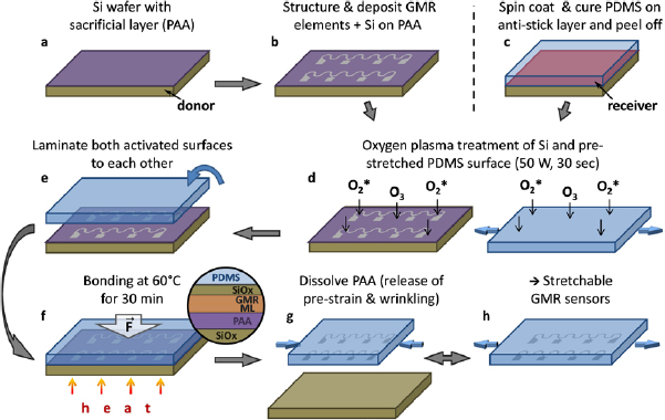
Figure 22. Process flow of the direct transfer printing: (a) and (b) preparation of GMR multilayers with Si capping layer on a PAA coated Si wafer (donor). (c) Spin coating and curing of a PDMS film (receiver) on an anti-stick layer coated carrier. (d) Oxygen plasma activation of donor and pre-stretched receiver substrate. (e) and (f) Heat and pressure assisted adhesion of both activated surfaces. The magnified view in (f) shows a cross section of the bonding interface region. The bonding is established between the top Si surface, which is oxidized to SiOx by the plasma and the activated PDMS (layers not drawn to scale). (g) Dissolving of the PAA sacrificial layer to detach the GMR structures from the donor substrate and release of the pre-strain in the receiver membrane to obtain a wrinkled morphology. (h) The transferred sensors can be elastically stretched in the direction of the pre-strain. [176] John Wiley & Sons. Copyright © 2015 WILEY-VCH Verlag GmbH & Co. KGaA, Weinheim.
Download figure:
Standard image High-resolution imageTwo different sensor designs have been demonstrated in this study to highlight the two main features enabled by the introduced transfer process. The first layout is an array of micro-sized GMR sensors with electrical contacts, which requires two-step lithography to be performed, to demonstrate the enhanced fabrication potential in terms of miniaturization and level of complexity compared to previous fabrication approaches. The second sensor design is a serpentine meander, as already introduced above, to demonstrate the increased stretchability using the direct transfer method.
4.2. Direct transfer of GMR microsensor arrays
The microsensor array consists of five GMR multilayer test-structures, all of 6 µm width and different lengths, including one sensor shaped to a microscopic meander. As displayed in figures 23(a) and (b), each element is equipped with an electrode structure of Cr(5 nm)/Cu(50 nm) for reliable contacting, which was prepared by electron beam evaporation and a second photolithographic patterning step. Because microsensor arrays are mainly used to detect spatially confined and small magnetic fields in the range of several oersteds only [134], the sensing elements in this design consist of highly sensitive ![$\left[{\rm Py}/{\rm Cu} \right]_{30}^{2{\rm nd}}$](https://content.cld.iop.org/journals/0022-3727/53/8/083002/revision2/dab52cfieqn056.gif) multilayers [93]. Two of the sensor elements, a stripe of 60 µm length and the meander, are displayed in figures 23(c) and (d), respectively.
multilayers [93]. Two of the sensor elements, a stripe of 60 µm length and the meander, are displayed in figures 23(c) and (d), respectively.
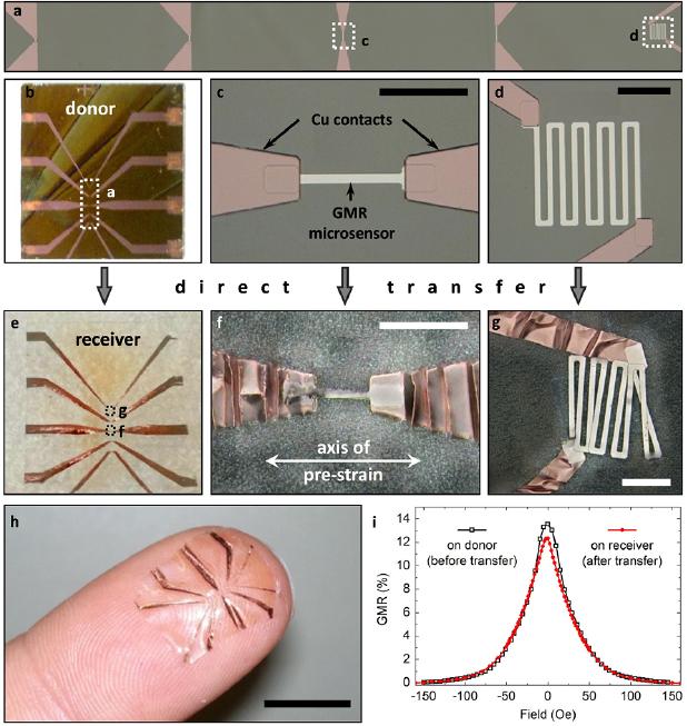
Figure 23. Direct transfer of a GMR microsensor array: (a) Microscope image of the array of five ![$\left[{\rm Py}/{\rm Cu} \right]_{30}^{2{\rm nd}}$](https://content.cld.iop.org/journals/0022-3727/53/8/083002/revision2/dab52cfieqn057.gif) GMR elements (four stripes of different length and one meander, widths: 6 µm). (b) Entire structure including contacts on the rigid donor substrate. (c) and (d) Magnified views of the 60 µm microsensor stripe and the meander, with contacts to the electrodes, respectively. (e)–(g) Microsensors transferred to the receiving substrate using a uniaxial pre-strain of 20%, as indicated in (f). All scale bars: 50 µm. (h) The transferred microsensor array can conform to the soft and curved surface of a fingertip (scale bar: 10 mm). (i) GMR characteristics of the meander microsensor element before (
GMR elements (four stripes of different length and one meander, widths: 6 µm). (b) Entire structure including contacts on the rigid donor substrate. (c) and (d) Magnified views of the 60 µm microsensor stripe and the meander, with contacts to the electrodes, respectively. (e)–(g) Microsensors transferred to the receiving substrate using a uniaxial pre-strain of 20%, as indicated in (f). All scale bars: 50 µm. (h) The transferred microsensor array can conform to the soft and curved surface of a fingertip (scale bar: 10 mm). (i) GMR characteristics of the meander microsensor element before ( ) and after (*) the transfer process. [176] John Wiley & Sons. Copyright © 2015 WILEY-VCH Verlag GmbH & Co. KGaA, Weinheim.
Download figure:
Standard image High-resolution imageFigures 23(e)–(g) shows the same structures as above, respectively, after the transfer to the receiving PDMS membrane. For the microsensor array, a uniaxial pre-strain of 20% along the sensor stripes was used, as indicated in figure 23(f). In the case of uniaxial pre-strain, the transverse direction has to be pre-stretched as well, in order to compensate for the Poisson's contraction, avoiding the destruction of transferred structures upon strain release. The final sensor array can be applied to any curved or soft surfaces, as demonstrated in figure 23h with the GMR microsensors positioned on a fingertip. The functionality of the transferred sensors is proven by GMR measurements on the meander element before and after the transfer process (figure 23i). Both curves show a similar GMR signal with high sensitivities at small magnetic fields.
4.3. Direct transfer of compliant GMR meander sensors
As the second sensor design, the macroscopic serpentine meander with four contact pads, according to figure 10, was used. In this case, ![$\left[{\rm Co}/{\rm Cu} \right]_{50}^{1{\rm st}}$](https://content.cld.iop.org/journals/0022-3727/53/8/083002/revision2/dab52cfieqn059.gif) GMR multilayers were chosen. Figures 24(a) and (b) shows the same element before and after the transfer to the receiving PDMS membrane, respectively, using a biaxial pre-strain of 25% × 25%. A confocal microscopy image of the serpentine trace after the transfer is included in figure 24(c) showing the biaxially wrinkled morphology of the GMR film with an amplitude of ≈2.5 µm and a period of ≈11.7 µm. The theoretically estimated value of the wrinkling period according to the previously employed model by N. Bowden et al. [115], was computed to λ = 17.8 µm. This theoretical consideration, however, did not take into account the existing stiffness modification of the PDMS surface by the used oxygen plasma treatment [129].
GMR multilayers were chosen. Figures 24(a) and (b) shows the same element before and after the transfer to the receiving PDMS membrane, respectively, using a biaxial pre-strain of 25% × 25%. A confocal microscopy image of the serpentine trace after the transfer is included in figure 24(c) showing the biaxially wrinkled morphology of the GMR film with an amplitude of ≈2.5 µm and a period of ≈11.7 µm. The theoretically estimated value of the wrinkling period according to the previously employed model by N. Bowden et al. [115], was computed to λ = 17.8 µm. This theoretical consideration, however, did not take into account the existing stiffness modification of the PDMS surface by the used oxygen plasma treatment [129].

Figure 24. Direct transfer of a compliant meander GMR sensor: (a) a macroscopic serpentine meander element consisting of a ![$\left[{\rm Co}/{\rm Cu} \right]_{50}^{1{\rm st}}$](https://content.cld.iop.org/journals/0022-3727/53/8/083002/revision2/dab52cfieqn060.gif) GMR multilayer on the donor substrate. (b) The same meander element after the transfer to a free-standing PDMS membrane using a biaxial pre-strain of 25% × 25%. All scale bars: 5 mm. (c) A confocal microscopy image showing the topography of the wrinkled GMR multilayer element in (b). (d) SEM images of a FIB cut through the transferred GMR film showing the good adhesion of the wrinkled magnetic nanomembrane to the PDMS support (scale bar: 5 µm). (e) GMR characteristics of the serpentine meander before (
GMR multilayer on the donor substrate. (b) The same meander element after the transfer to a free-standing PDMS membrane using a biaxial pre-strain of 25% × 25%. All scale bars: 5 mm. (c) A confocal microscopy image showing the topography of the wrinkled GMR multilayer element in (b). (d) SEM images of a FIB cut through the transferred GMR film showing the good adhesion of the wrinkled magnetic nanomembrane to the PDMS support (scale bar: 5 µm). (e) GMR characteristics of the serpentine meander before ( ) and after (
 ) the transfer process. [176] John Wiley & Sons. Copyright © 2015 WILEY-VCH Verlag GmbH & Co. KGaA, Weinheim.
Download figure:
Standard image High-resolution imageThe good adhesion of the plasma induced bonding between the GMR multilayer and the PDMS membrane is demonstrated by means of an SEM/FIB investigation of the sensor cross-section (figure 24(d)). The images show that the GMR multilayer is firmly attached to the soft PDMS, even throughout the wrinkles. The magnetoelectrical performance of the ![$\left[{\rm Co}/{\rm Cu} \right]_{50}^{1{\rm st}}$](https://content.cld.iop.org/journals/0022-3727/53/8/083002/revision2/dab52cfieqn063.gif) multilayer meander on the donor and the receiver substrate is shown in figure 24(e). The GMR curve determined in this measurement reaches a value of 46% after the transfer from 57% beforehand. This, however, is not an evidence of a reduced total GMR magnitude in the transferred sensor element, as the magnetic sensor also reveals an increased saturation field. This broadening of the GMR curve is attributed to the appearance of out-of-plane components of the magnetization at the locations of the tilted wrinkle side-walls, which run perpendicular to the applied magnetic field. This effect becomes pronounced in this sample due to the large amplitude of biaxial wrinkles (amplitude/period = 0.4) compared to the previous cases with rather shallow parallel wrinkles (amplitude/period = 0.04), which were thermally induced [40]. A similar effect was already observed by means of perpendicular buckles due to the Poisson contraction in the case of stretchable spin valves [21] described above.
multilayer meander on the donor and the receiver substrate is shown in figure 24(e). The GMR curve determined in this measurement reaches a value of 46% after the transfer from 57% beforehand. This, however, is not an evidence of a reduced total GMR magnitude in the transferred sensor element, as the magnetic sensor also reveals an increased saturation field. This broadening of the GMR curve is attributed to the appearance of out-of-plane components of the magnetization at the locations of the tilted wrinkle side-walls, which run perpendicular to the applied magnetic field. This effect becomes pronounced in this sample due to the large amplitude of biaxial wrinkles (amplitude/period = 0.4) compared to the previous cases with rather shallow parallel wrinkles (amplitude/period = 0.04), which were thermally induced [40]. A similar effect was already observed by means of perpendicular buckles due to the Poisson contraction in the case of stretchable spin valves [21] described above.
4.4. Stretching test of compliant GMR meander sensors
The chosen meander geometry of the transferred sensing elements have previously been shown to enhance the stretchability of GMR multilayers grown onto PDMS substrates [128]. Hence, this type of sensor was applied to demonstrate the increased stretchability achieved using the direct transfer printing method with mechanically induced pre-strain. The stretching test was performed according to the previously utilized stretching setup and procedure.
The sensor characteristics for in situ recording of GMR curves as the sample is stretched is plotted in figure 25(a) and shows no significant changes, except for a small drop beyond 20% strain. In figure 25(b) the GMR magnitude and the sensor resistance at zero fields is presented in dependence of the applied tensile strain. Both values are subject to only small changes up to a uniaxial deformation of 30% before the electrical connection is lost. This data demonstrates the compliant properties and invariance of the prepared magnetic sensing elements to application relevant tensile deformations. Especially the maintained resistance, in contrast to the behaviour of the spin valves described in the previous section, proves that no or only very few cracks are induced in the wrinkled GMR nanomembrane as it expands. The obtained stretchability of 30% was attributed to a combination of the wrinkling due to mechanically induced pre-strain in the stretching direction (≈25%) and the additional compliance of the meander pattern (≈5%) [128]. A sensor element mounted to the in situ stretching stage is displayed in the inset of figure 25(b).
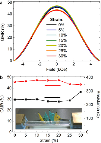
Figure 25. Stretching test of a transferred GMR meander: (a) GMR curves of a ![$\left[{\rm Co}/{\rm Cu} \right]_{50}^{1{\rm st}}$](https://content.cld.iop.org/journals/0022-3727/53/8/083002/revision2/dab52cfieqn064.gif) multilayer meander transferred to a PDMS membrane, measured at different strains applied along the meander, as indicated in the legend. The pre-strain used for the transfer process was 25% × 25%. (b) GMR magnitude (
multilayer meander transferred to a PDMS membrane, measured at different strains applied along the meander, as indicated in the legend. The pre-strain used for the transfer process was 25% × 25%. (b) GMR magnitude ( ) and sensor resistance (▪) with increasing tensile strain. The inset shows the sensor mounted to the stretching stage and contacted for 4-point in situ GMR characterization. [176] John Wiley & Sons. Copyright © 2015 WILEY-VCH Verlag GmbH & Co. KGaA, Weinheim.
Download figure:
Standard image High-resolution imageThese results denote a one order of magnitude increase in stretchability and miniaturization of compliant GMR multilayers compared to the previously described approach of sensor preparation directly onto the elastomeric substrate with thermally induced pre-strain [40, 128]. Both, the GMR characteristic and sensor resistance remain almost unchanged over the entire range of strain, which was not achieved by any other means so far. Since almost no resistance change is associated with the tensile deformation as well, the sensor elements introduced here are truly strain invariant. Although an unchanged resistance up to high tensile deformations was also observed in the case of stretchable spin valves after the first stretching, a severe damage occurred, when these elements were released back to their fully relaxed state [21]. This effect is neither observed nor expected in the present case, due to the absence of cracks in the functional GMR layer. Furthermore, the direction of the pre-strain can be controlled in order to achieve either uniaxial or biaxial stretchability. The presented direct transfer approach is not limited to magnetic nanomembranes, which renders the combination of magnetoelectronic components with other stretchable functional elements possible to form smart multi-functional and interactive electronic systems triggered by magnetic fields.
5. Highly compliant magnetoelectronics on ultra-thin foils
In order to go beyond the possibilities provided by using PDMS as elastic support for GMR thin films, as for all cases discussed so far, the concept of imperceptible electronics [24] has been adapted to magnetoelectronics. This approach relies on the fabrication of functional thin film electronic elements on very thin (<2 µm) polymeric membranes. The reduction of the flexible substrate to a minimum thickness provides unique mechanical properties of extreme bendability and light-weight to the entire electronic device [24, 173] and, hence, these components readily conform to ubiquitous objects. Both, organic and inorganic electronic components have been very recently introduced to imperceptible electronics. Besides electronic circuity [180] also tactile sensors [24], light emitting diodes [23], solar cells [34], as well as thermoelectric elements [15] have been realized. Magnetosensitive nanomembranes fabricated onto such thin plastic foils resulted in ultra-thin GMR sensors that are extremely flexible, light-weight and durable. These imperceptible magneto-sensitive elements have particular impact on electronic skin systems [17, 56], which paves the way to go beyond the imitation of natural skin functionalities and could equip the recipient with the 'sixth sense' of magnetoception [72, 73]. However, the presented GMR foils could also lead to outstanding uniaxial and biaxial stretchabilities of far beyond 100% with a very stable performance and long-term persistence.
Highly sensitive ![$\left[{\rm Py}/{\rm Cu} \right]_{30}^{2{\rm nd}}$](https://content.cld.iop.org/journals/0022-3727/53/8/083002/revision2/dab52cfieqn066.gif) multilayer elements fabricated on 1.4 µm biaxially-oriented polyethylene terephthalate (PET) revealed a typical GMR ratio of 13.2% at room temperature and their magnetosensitive behaviour appeared to be in very good agreement to their rigid silicon based counterparts [17]. Also other imperceptible GMR multilayer systems including spin valve stacks have been prepared with similar results [17, 56], confirming their potential for a wide range of magnetic sensorics applications. The extreme light-weight and compliant nature of the sensor elements allows them to be operated on virtually any soft material and arbitrarily formed surface [17]. On the other hand, the sensor foil is robust and tearproof. If worn on skin, these magnetic sensing elements intimately conform to any complex epidermal shape and simultaneously follow the surface's motions and deformations. As the presence of such thin and compliant on-skin electronic components is haptically not perceived by the recipient, they are denoted imperceptible.
multilayer elements fabricated on 1.4 µm biaxially-oriented polyethylene terephthalate (PET) revealed a typical GMR ratio of 13.2% at room temperature and their magnetosensitive behaviour appeared to be in very good agreement to their rigid silicon based counterparts [17]. Also other imperceptible GMR multilayer systems including spin valve stacks have been prepared with similar results [17, 56], confirming their potential for a wide range of magnetic sensorics applications. The extreme light-weight and compliant nature of the sensor elements allows them to be operated on virtually any soft material and arbitrarily formed surface [17]. On the other hand, the sensor foil is robust and tearproof. If worn on skin, these magnetic sensing elements intimately conform to any complex epidermal shape and simultaneously follow the surface's motions and deformations. As the presence of such thin and compliant on-skin electronic components is haptically not perceived by the recipient, they are denoted imperceptible.
5.1. Ultra-stretchable GMR sensors
Although the used ultra-thin PET foil is hardly stretchable itself, imperceptible electronics offers an elegant route to facilitate very high levels of tensile strain without any sacrifices in device performance by a facile post-fabrication transfer step onto a pre-strained elastomer [23, 24, 34], as illustrated in figure 26(a). When the rubber tape is allowed to relax, wrinkles are formed not solely in the GMR thin film, but in the entire imperceptible sensor foil (i.e. GMR layer + ultra-thin PET membrane), instead. In the case of GMR elements, this leads to magnetic sensing devices that can reversibly attain nearly ten-fold higher stretch deformations over the previously described concepts, with remarkable long-term stability. Furthermore, the magneto-sensitive elements can be prepared to withstand large uniaxial or biaxial a deformations, which highlights their universal application potential for stretchable electronic systems.

Figure 26. Lamination of imperceptible GMR multilayers onto pre-stretched adhesive tape: (a) The post fabrication step to obtain ultra-stretchable GMR sensors from imperceptible elements by face-down lamination onto a highly pre-stretched stripe of VHB tape. Four contact pads are reaching beyond the tape (top). Relaxing the elastomer results in out-of-plane wrinkling of the sensor foil and enables re-stretching (bottom). (b) and (c) Optical microscopy (scale bar: 200 µm) and SEM (scale bar: 100 µm) top view images, respectively, revealing the wrinkled structure of the sensor surface in the relaxed state. (d) GMR curves of an imperceptible ![$\left[{\rm Py}/{\rm Cu} \right]_{30}^{2{\rm nd}}$](https://content.cld.iop.org/journals/0022-3727/53/8/083002/revision2/dab52cfieqn067.gif) multilayer element at a flat state before lamination onto the pre-stretched VHB support (
multilayer element at a flat state before lamination onto the pre-stretched VHB support ( ) and at a highly wrinkled state after release of pre-strain (
 ). Reprinted by permission from Springer Nature Customer Service Centre GmbH: Nature Communications [17] (2015).
Download figure:
Standard image High-resolution imageThe presence of a thin flexible, but not stretchable polymer membrane supports the delicate GMR nanomembrane throughout its corrugations and protects it from high mechanical stresses during arbitrary deformations of the sensor device, which allows for very high stretchabilities. The maximum compression and therefore stretchability of the sensors is mainly determined by the pre-strain magnitude of the elastomer along the respective direction before lamination and limited by the packing density of the out-of-plane folds [24]. In order to test the limits of the uniaxial stretchability for the used combination of materials, large pre-strains of 600% on a highly stretchable adhesive tape (VHB™ 4905, 3M) were used for the fabrication of compliant devices. For such high pre-strains, the VHB tape is unable to relax back to its initial length upon release, as adjacent buckles start to push against each other. The resulting equilibrium state is defined as the reference in stretching experiments, which corresponds to 0% strain. Optical microscopy and SEM top view images provided in figures 26(b) and (c), respectively, reveal the highly wrinkled topography of the sensors after the relaxation of the pre-strain.
The magneto-sensitive capabilities of the presented elements are not affected by the post-processing, as shown in figure 26(d) on a GMR device measured before and after the lamination and wrinkling on the VHB tape. The GMR elements are laminated face down to the pre-stretched VHB tape, which in turn acts as an encapsulation for the functional magnetic layer between the stretchable tape and the ultra-thin PET foil, as visualized by SEM imaging of the sample's cross-section in figure 27(a) prepared by FIB milling. In order to realize reliable contacting of the buried GMR layer, elongated contact pads that after the lamination reach sideways beyond the stretchable tape (figure 26(a)) were used. Hence, contacting to thin copper wires was done on the metalized bottom side of the free waving PET foil using conductive silver paste.
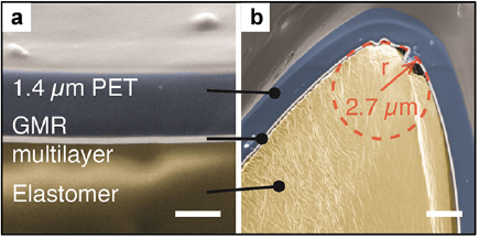
Figure 27. Cross-sectional views of the encapsulated GMR sensing layer: SEM images of FIB cuts through the wrinkled sensor foil on the relaxed VHB tape. The GMR nanomembrane is encapsulated between the ultra-thin PET and the stretchable adhesive tape, as indicated in (a). Some parts of the magnetoresistive foil on the tip of the buckles are bent into radii of curvature of less than 3 µm (b). Reprinted by permission from Springer Nature Customer Service Centre GmbH: Nature Communications [17] (2015).
Download figure:
Standard image High-resolution imageFigure 27(b) reveals that, for high uniaxial pre-strains, some parts of the magnetoresistive foil on the tip of the buckles are bent into radii of curvature of less than 3 µm, while the sensor not only remains functional, but also maintains its full performance. The locations of the presented FIB cuts in figures 27(a) and (b) are marked in the top view SEM image in figure 26(c) by the labels (l) and (r), respectively.
The stretchability of the post processed sensor elements has been investigated in accordance to the previously used stretching setup and procedure, as well. A top view of a mounted and contacted stretchable ![$\left[{\rm Py}/{\rm Cu} \right]_{30}^{2{\rm nd}}$](https://content.cld.iop.org/journals/0022-3727/53/8/083002/revision2/dab52cfieqn070.gif) GMR sensing element in a relaxed (left) and the fully stretched state (right) is provided in figure 28a. The axis of the applied magnetic field was perpendicular to the sensor stripe (along the wrinkles). The strain was increased in steps of 10% with a rate of 100 µm s−1 (0.7 % s−1) between the magnetoelectric measurements. The recorded GMR curves at different tensile strain levels along the direction of pre-strain are congruent with each other, as presented in figure 28(b). The progression of the GMR magnitude and the relative resistance change due to stretching of the sensor are plotted as a function of the uniaxial deformation in figure 28(c). Both values also remain unchanged over this entire strain regime (relative standard deviations: RSDR < 0.1%; RSDGMR < 0.6%). At 270%, the PET foil with the GMR layer is fully elongated and the wrinkles vanish, as shown in the right hand picture of figure 28(a). Once the foil is stretched even slightly beyond its fully flat state, the resistance rapidly increases due to some ultimate tensile deformations of the flattened GMR layer (shaded region in figure 28(c)). Surprisingly, by overstretching the GMR element by several percent, here from 270% to 275%, the magnitude of the GMR effect is not reduced. The respective GMR curve for the overstretched sensor, shows a significant increase of its saturation field instead (figure 28(b)), which may be due to a modification of the interlayer exchange coupling by slightly reduced layer thicknesses in the strained GMR film [50]. This effect, however, is fully reversible and the reduced saturation field is restored as soon as some strain is released.
GMR sensing element in a relaxed (left) and the fully stretched state (right) is provided in figure 28a. The axis of the applied magnetic field was perpendicular to the sensor stripe (along the wrinkles). The strain was increased in steps of 10% with a rate of 100 µm s−1 (0.7 % s−1) between the magnetoelectric measurements. The recorded GMR curves at different tensile strain levels along the direction of pre-strain are congruent with each other, as presented in figure 28(b). The progression of the GMR magnitude and the relative resistance change due to stretching of the sensor are plotted as a function of the uniaxial deformation in figure 28(c). Both values also remain unchanged over this entire strain regime (relative standard deviations: RSDR < 0.1%; RSDGMR < 0.6%). At 270%, the PET foil with the GMR layer is fully elongated and the wrinkles vanish, as shown in the right hand picture of figure 28(a). Once the foil is stretched even slightly beyond its fully flat state, the resistance rapidly increases due to some ultimate tensile deformations of the flattened GMR layer (shaded region in figure 28(c)). Surprisingly, by overstretching the GMR element by several percent, here from 270% to 275%, the magnitude of the GMR effect is not reduced. The respective GMR curve for the overstretched sensor, shows a significant increase of its saturation field instead (figure 28(b)), which may be due to a modification of the interlayer exchange coupling by slightly reduced layer thicknesses in the strained GMR film [50]. This effect, however, is fully reversible and the reduced saturation field is restored as soon as some strain is released.
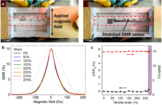
Figure 28. Stretching of imperceptible GMR sensors: (a) A ![$\left[{\rm Py}/{\rm Cu} \right]_{30}^{2{\rm nd}}$](https://content.cld.iop.org/journals/0022-3727/53/8/083002/revision2/dab52cfieqn071.gif) sample mounted to the in situ stretching stage relaxed (left) and fully elongated (right). The arrow in the left image indicates the axis of the applied magnetic field. (b) GMR curves recorded for strains from 0% to 275%, according to the legend. (c)
sample mounted to the in situ stretching stage relaxed (left) and fully elongated (right). The arrow in the left image indicates the axis of the applied magnetic field. (b) GMR curves recorded for strains from 0% to 275%, according to the legend. (c)  GMR magnitude and ▪ resistance change normalized to 0% strain (R0 = 9.7 Ω) as a function of applied strain. The shaded region indicates overstretching. Reprinted by permission from Springer Nature Customer Service Centre GmbH: Nature Communications [17] (2015).
Download figure:
Standard image High-resolution imageTo investigate the long-term behaviour and reliability of the imperceptible, highly stretchable magnetoresistive elements upon deformation, cyclic loading experiments were performed. Wrinkled ![$\left[{\rm Py}/{\rm Cu} \right]_{30}^{2{\rm nd}}$](https://content.cld.iop.org/journals/0022-3727/53/8/083002/revision2/dab52cfieqn073.gif) multilayer sensors were prepared, as described, using a pre-strain of 150% for lamination. The strain interval for the repeated loading and unloading was set from 50% to 100% to meet the maximum permanent operation limits of the used test setup and to avoid slacking due to the viscoelasticity of the rubber tape during this long-term test. The investigated magnitude of strain meets the typical demands for most on-skin and in vivo operations. Cyclic loading was conducted at a rate of 150 µm s−1 (1.25 % s−1), 1 s delay at the reversal points and 9 cycles were driven between the GMR measurements at both reversal points.
multilayer sensors were prepared, as described, using a pre-strain of 150% for lamination. The strain interval for the repeated loading and unloading was set from 50% to 100% to meet the maximum permanent operation limits of the used test setup and to avoid slacking due to the viscoelasticity of the rubber tape during this long-term test. The investigated magnitude of strain meets the typical demands for most on-skin and in vivo operations. Cyclic loading was conducted at a rate of 150 µm s−1 (1.25 % s−1), 1 s delay at the reversal points and 9 cycles were driven between the GMR measurements at both reversal points.
The GMR characteristics for the 1st and 1000th loading cycle are displayed in figure 29(a) for the low- and high-strain state. They show no evidence of fatigue or any other influence of the repeated loading scenario. The recorded traces are congruent with each other and to the control measurement of the as-prepared sensor in the fully relaxed state (0% strain). Figure 29(b) plots the GMR magnitude and relative resistance change (normalized to the as-prepared sensor before lamination) for the high (100%) and low (50%) strain reversal points versus cycle number. The GMR values remain at their high level throughout the 1000 loading cycles, and even the electrical resistance of the nanomembrane stays nearly unchanged (far less than 1% resistance change over 1000 cycles). Although a slight resistance increase is observed over the first 200 cycles, saturation sets in and no further fatigue occurs. This is remarkable for a fully functional sensor element, as such a long-term stability is rarely observed even for simple stretchable conductors [4].

Figure 29. Reliability upon cyclic loading: (a) GMR curves of a ![$\left[Py/Cu \right]_{30}^{{{2}^{nd}}}$](https://content.cld.iop.org/journals/0022-3727/53/8/083002/revision2/dab52cfieqn074.gif) element under cyclic loading between 50% strain (
element under cyclic loading between 50% strain ( ) and 100% strain (
 ), measured after the first cycle (open symbols) and after cycle No. 1000 (closed symbols). The characteristic of the as-prepared sample (at 0% strain) is also plotted in dashed gray. (b)
  GMR magnitude and ▪ resistance change normalized to the as-prepared sample at 50% strain (open symbols) and 100% strain (closed symbols) as a function of cycle number. Reprinted by permission from Springer Nature Customer Service Centre GmbH: Nature Communications [17] (2015).
Download figure:
Standard image High-resolution imageThese results proved in a compelling way that imperceptible GMR sensors are rugged and very durable, a prerequisite for 'real world' electronic skin and stretchable electronics applications. The here presented stretchable GMR sensors outperform all previously introduced elements in terms of stretchability, reliability and application potential. Since both the GMR magnitude and the sensor's resistance are invariant to stretching, no additional strain calibration is necessary and the sensor elements can be regarded as truly strain invariant over a large range of tensile deformation. The outstanding resilience of the presented imperceptible and stretchable GMR elements against high and repeated mechanical deformations can be attributed to the ductile properties of the used metals in the Co/Cu and Py/Cu GMR stacks, in particular those of copper. It has recently been shown, that thin copper films are much less susceptible to aging upon repeated deformations in the concept of imperceptible electronics compared to e.g. Al or Ag electrodes [15].
5.2. Biaxial stretchability
The ultimate goal for stretchable electronic systems is to be compliant also against high biaxial deformations. Sensor elements ideally show orthogonality of arbitrarily imposed deformations to the detected signal. For the case of GMR sensors, this means that both, the magnetoelectric characteristic and the resistance, are not altered by any deformation, including areal expansion of the device. Using biaxial pre-strain, the described GMR sensing elements can also be stretched in all lateral directions simultaneously [17]. This feature is demonstrated in figure 30 by the operation of an imperceptible sensor on an expanding diaphragm. The soft diaphragm was made of VHB tape and forms a sealed chamber, which is filled with water fed by a syringe through an inlet/outlet tubing. Pumping water into the chamber forces the VHB diaphragm to bulge accordingly. An imperceptible ![$\left[{\rm Co}/{\rm Cu} \right]_{30}^{2{\rm nd}}$](https://content.cld.iop.org/journals/0022-3727/53/8/083002/revision2/dab52cfieqn078.gif) sensor element was attached face down to the top of the VHB membrane while it is strongly inflated, which generates the strong biaxial pre-strain. The GMR sensor was contacted with 50 µm copper wires and silver paste before lamination. Upon deflating the diaphragm, the attached sensor is biaxially compressed and wrinkles accordingly. A photograph of the biaxially stretched GMR sensor on the inflated diaphragm being placed between the pole shoes of a magnetoelectric characterization setup is provided in figure 30(a).
sensor element was attached face down to the top of the VHB membrane while it is strongly inflated, which generates the strong biaxial pre-strain. The GMR sensor was contacted with 50 µm copper wires and silver paste before lamination. Upon deflating the diaphragm, the attached sensor is biaxially compressed and wrinkles accordingly. A photograph of the biaxially stretched GMR sensor on the inflated diaphragm being placed between the pole shoes of a magnetoelectric characterization setup is provided in figure 30(a).
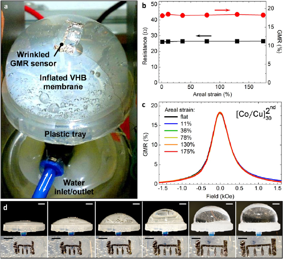
Figure 30. Biaxial stretchability on an expanding diaphragm: (a) Biaxially stretchable ![$\left[{\rm Co}/{\rm Cu} \right]_{30}^{2{\rm nd}}$](https://content.cld.iop.org/journals/0022-3727/53/8/083002/revision2/dab52cfieqn079.gif) GMR sensor on a VHB diaphragm inflated by water. (b) GMR magnitude (
GMR sensor on a VHB diaphragm inflated by water. (b) GMR magnitude ( ) and sensor resistance (▪) as a function of applied areal strain. (c) GMR curves recorded for different inflation states. The corresponding areal strain was estimated from the side view photographs of each inflated state shown in the upper row of (d). The bottom row shows the biaxially wrinkled sensor for the inflation above, respectively. Scale bars: 10 mm (top), 5 mm (bottom). Reprinted by permission from Springer Nature Customer Service Centre GmbH: Nature Communications [17] (2015).
Download figure:
Standard image High-resolution imageFigure 30(b) shows the GMR characterization results of the ![$\left[{\rm Co}/{\rm Cu} \right]_{30}^{2{\rm nd}}$](https://content.cld.iop.org/journals/0022-3727/53/8/083002/revision2/dab52cfieqn081.gif) sensor on the diaphragm at different inflation states, from planar to 175% areal strain. As for the uniaxial case, the GMR magnitude as well as the absolute sensor resistance remain at a constant level with stretching. Furthermore, for biaxial stretching, the GMR curves at different strains are congruent with each other as well (figure 30(c)). A set of images showing the inflation of the diaphragm (top) and the respective wrinkling of the sensor (bottom) for all strain levels characterized in this experiment is given in figure 30(d).
sensor on the diaphragm at different inflation states, from planar to 175% areal strain. As for the uniaxial case, the GMR magnitude as well as the absolute sensor resistance remain at a constant level with stretching. Furthermore, for biaxial stretching, the GMR curves at different strains are congruent with each other as well (figure 30(c)). A set of images showing the inflation of the diaphragm (top) and the respective wrinkling of the sensor (bottom) for all strain levels characterized in this experiment is given in figure 30(d).
The side-view photographs at the top were used to estimate the amount of areal strain at the sensor position.
The geometry of an expanding diaphragm represents several potential application scenarios for biaxially compliant magnetic sensors, e.g. soft diaphragm actuators made of electro-active polymers [181, 182] or multifunctional medical implants on muscular biological tissue [77]. Using the stretchable sensor on the diaphragm, it is possible for example to easily detect its inflation by adding a permanent magnet at a central position into the water chamber, as shown in figure 31(a). In this configuration, the sensor resistance provides a measure for the distance to the permanent magnet, and hence the inflation of the diaphragm (figure 31(b)). For this task, a ![$\left[{\rm Co}/{\rm Cu} \right]_{30}^{2{\rm nd}}$](https://content.cld.iop.org/journals/0022-3727/53/8/083002/revision2/dab52cfieqn082.gif) element was chosen, as it gives the largest GMR signal in the typical field range (<500 Oe) of a permanent magnet in few millimeters to few centimeters distance, among the investigated multilayer systems (figure 6 and table 2) [136]. The obtained sensor signal for a permanently pulsating diaphragm is displayed in figure 31(c), which readily monitors its inflation and deflation in real time.
element was chosen, as it gives the largest GMR signal in the typical field range (<500 Oe) of a permanent magnet in few millimeters to few centimeters distance, among the investigated multilayer systems (figure 6 and table 2) [136]. The obtained sensor signal for a permanently pulsating diaphragm is displayed in figure 31(c), which readily monitors its inflation and deflation in real time.
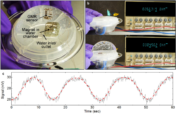
Figure 31. Demonstrator of a magnetic detector for soft diaphragm actuation: (a) Inflated diaphragm with compliant ![$\left[{\rm Co}/{\rm Cu} \right]_{30}^{2{\rm nd}}$](https://content.cld.iop.org/journals/0022-3727/53/8/083002/revision2/dab52cfieqn083.gif) GMR sensor and a permanent magnet fixed in the water chamber on the plastic tray. (b) The resistance of the sensor is displayed on a directly connected multimeter for the deflated (top) and inflated (bottom) diaphragm. (c) Recorded sensor signal for a pulsating diaphragm demonstrating the dynamic magnetic detection of its inflation. The dashed line is a smoothed graph to guide the eye Reprinted by permission from Springer Nature Customer Service Centre GmbH: Nature Communications [17] (2015).
GMR sensor and a permanent magnet fixed in the water chamber on the plastic tray. (b) The resistance of the sensor is displayed on a directly connected multimeter for the deflated (top) and inflated (bottom) diaphragm. (c) Recorded sensor signal for a pulsating diaphragm demonstrating the dynamic magnetic detection of its inflation. The dashed line is a smoothed graph to guide the eye Reprinted by permission from Springer Nature Customer Service Centre GmbH: Nature Communications [17] (2015).
Download figure:
Standard image High-resolution image
With the demonstration of biaxial stretchability, this novel platform for magnetic sensorics revealed excellent capabilities in terms of strain invariance. The presented GMR elements are compliant to literally any kind of deformation that can occur on an arbitrary surface. These versatile features are imparted to the magnetoelectronic devices by their ultra-thin and flexible, yet robust polymeric support.
6. Conclusions
This review highlights the successful establishment of stretchable GMR based magnetic sensorics, describing the entire development from the first attempts to verify the functional concept [40] to the realization of ready-to-use highly compliant and strain invariant sensor devices with remarkable robustness [17]. The developed technology platform offers significant application potential in the fields of soft robotics, medical implants, smart skins and textiles as well as consumer electronics. Lithographically structured magnetoresistive layer stacks have been deposited [21, 40] or transferred [17, 176] onto elastomeric films, which serve as compliant supports and determine the unique mechanical properties of the sensor elements. Stretchability of the GMR sensors is achieved by certain morphologic features, e.g. wrinkles brought into the magnetosensitive thin films, which accommodate the applied tensile deformation while maintaining the electrical and magnetic integrity of the devices.
The morphologic feature that was mostly applied to obtain stretchable GMR elements is wrinkling [126], which occurs if a soft material with a harder skin is compressed laterally. The utilization of a thermally induced pre-strain led to the realization of the world's first elastically stretchable magnetic sensor element [40]. The magnetoelectric performance of this first demonstrator was identical to GMR multilayer sensors fabricated on conventional rigid substrates and did not degrade if stretched by several percent. Based on that, several optimizations and advancements were conducted in order to enhance the sensor properties [17, 21, 136, 176]. The sensitivity to low magnetic fields, as required for most e-skin and biomedical applications, was increased by lowering the magnetic coupling strength between the ferromagnetic layers, using magnetically softer materials in the GMR stack [136] or by replacing the GMR multilayers by more advanced spin valve stacks [21]. The application of spin valves also gave rise to an improved stretchability by incorporating predetermined periodic fracturing sites in combination with deposition-induced random wrinkles [21].
Increasing the resilience against tensile deformation without relying on crack formation has been achieved by using mechanically instead of thermally induced pre-strain. For this purpose, a novel fabrication process was introduced that allows transferring the GMR sensor devices from a rigid donor substrate to a pre-strained rubber membrane, resulting in stretchabilities of about 30% [176]. The developed direct transfer process also greatly enhances the miniaturization and level of complexity of the compliant GMR devices, as their initial preparation can be done on conventional rigid substrates. Therefore, entire microsensor arrays including electrode structures could be transferred to elastomeric receiver substrates in a single step [176].
The most recent breakthrough in stretchable magnetoelectronics came with the preparation of GMR multilayer elements onto ultra-thin (1.4 µm) plastic membranes, and laminating them onto highly pre-stretched rubber tape. This fabrication approach results in large stretchabilities of up to 270% without altering any of their magnetoelectric characteristics; hence they are truly strain invariant. These magnetic sensors can even be stretched biaxially and showed a remarkable durability by enduring 1000 loading cycles without any fatigue.
With the technical development described in this review, the key attributes of stretchable GMR sensors (i.e. sensitivity, stretchability, miniaturization and durability) were improved by about two orders of magnitude [17, 21, 176] compared to the original sensor design [40]. As the developed platform was demonstrated with different kinds of magnetoresistive systems, including various multilayers [136] and spin valves [21], it represents a universal basis for the realization of stretchable GMR based sensorics and may even be extended to advanced spintronic systems [183] (e.g. magnetoresistive memories [184] or magnetic logic devices [185]).
6.1. Further development steps
The sensor layouts utilized for the development of stretchable magnetic sensorics have been designed as test structures that allow for fundamental investigations of the deformability and precise magnetoelectric characterization. Since photolithographic patterning of the magnetoresistive nanomembranes was successfully applied from the very beginning, the device structure can be adapted and scaled to meet the requirements for specific applications and design concepts. Patterning defined meander structures, for instance, will adapt the electrical parameters of individual sensing elements to the requirements of specific signal processing electronics [52]. Preparing the GMR elements into a Wheatstone bridge configuration would allow for a differential signal and may compensate for temperature drifts. An integration of compliant ferromagnetic structures [186] can help to realize magnetic biasing of the proposed GMR sensors to operate them around a defined working point of the GMR response curve in a fully stretchable design. This would not only allow using the maximum sensitivity of the respective elements but may also add a sense of directionality to lift the symmetry of magnetic field sign in GMR multilayers. Finally, detailed finite element method (FEM) mechanical modelling will be necessary to further guide improvements in mechanical performance of the stretchable magnetic field sensorics. Although the field of stretchable magnetoelectronics is currently limited to GMR (multilayers and spin valves), it will benefit from other sensor technologies and spintronic devices in the future.
For a successful commercialization of stretchable magnetic sensors, the long-term stability upon deformation far beyond 1000 loading cycles has to be verified. To further reduce the impact of mechanical stresses on the functional magnetic nanomembrane upon device deformation, the GMR film may be positioned in a neutral mechanical plane [173]. For the imperceptible magnetic sensors, this may be realized by chemical vapour depositions of parylene, which results in a thin and inert passivation layer [180]. It homogeneously covers also highly non-planar surfaces with a controllable thickness and is even biocompatible. This would also render these sensors suitable for more practical on-skin and in vivo use, by preventing long-term damage from aggressive body fluids. However, in accordance with the standards for specific utilization scenarios, further reliability tests against the persistent exposure to temperature changes, humidity, vibrations, wear and different chemical or biological environments have to be undertaken to qualify soft magnetic sensors for 'real world' applications. The impact from many of these lifetime-limiting factors should be minimized my means of smart and compliant packaging solutions, primarily. Apart from that, large area and high throughput production of compliant GMR sensorics has to be proven.
Future work will also focus on electrical and mechanical interfacing with other soft electronic components enabling for example signal conditioning [180] and multiplexing [24]. For this purpose, thin film transistor (TFT) architectures relying on organic [187] or inorganic [188] semiconductors may be applied. Both have recently demonstrated their outstanding suitability to provide functional signal conditioning circuitry on imperceptible electronics platforms [189, 190]. Wireless readout and remote sensing capabilities [39] will be also included to overcome the mayor issue of reliable electrical contacts. The integration of imperceptible magnetoelectronics with various functional elements on comparable platforms like solar cells [34], light emitting diodes [23], rechargeable batteries [38] as well as temperature [15] and tactile [24] sensors enables the realization of autonomous and versatile soft smart systems with a multitude of sensing and responsive features.
Acknowledgments
We acknowledge the great input of and fruitful discussions with Dr D Karnaushenko, Dr D D Karnaushenko, Dr J I Mönch, Dr G Lin (all IFW Dresden), Dr M Kaltenbrunner, Dr I Graz, Professor S Bauer (all JKU Linz), Professor T Someya (University Tokyo) and Professor T Sekitani (University Osaka).
This work was funded, in part, via the German Research Foundation DFG (Project SCHM 1298/15-1), BMBF Project Nanett (federal research funding of Germany FKZ: 03IS2011F and 03IS2011O) as well as by the European Research Council within the European Union's Seventh Framework Programme (FP7/2007-2013)/ERC Grant Agreement No. 306277.
Permissions for reprints were mainly conveyed through Copyright Clearance Center, Inc.