

Abstract
Magnesium alloys appear as one of the most promising materials for many applications such as degradable implants. However, their mechanical, corrosion and integration behaviors need to be optimized to comply with this application. The present paper focuses on laser-assisted maskless microdeposition (LAMM) of silver nanoparticles, a surface treatment aiming to modify the surface characteristics for better integration of the magnesium implant. The LAMM process parameters for obtaining desirable depositions are reported. The impacts of the LAMM process on the deposit and the substrate microstructure have been investigated using various characterization techniques. The results show that laser processing, which can lead to particle sintering in the deposit, can be fine-tuned to achieve necking between nano particles, while the nano-scale characteristics of the deposited layer is retained. Microstructural characterization reveals significant grain refinement in the immediate vicinity of the surface, providing evidence for the thermal impact of the laser process on the substrate. The thermal profiles of the deposit and the substrate during processing are further investigated by developing a 3D finite element modelling method. The implementation of the model allows us to better understand the origin of the fine-grained sublayer as well as the overall thermal impact of the current laser processing method on the substrate.
Export citation and abstract BibTeX RIS
1. Introduction
Magnesium alloys are considered as the most suitable metallic materials for degradable implant applications. Efforts to optimize the corrosion and mechanical behavior of these alloys usually concentrate on either alloy composition design [1–4] or microstructure tailoring [5–9]. Among all systems, magnesium–calcium alloys appear as the most promising candidate. Like magnesium, calcium is well tolerated by the body: it is a major element of bones (30–40 wt.% for an adult bone) [10]. Calcium may also promote the healing process with the formation of hydroxyapatite [11, 12]. Also increasing the calcium content has been reported to improve mechanical behaviour [13, 14]. However, a higher degradation rate in simulated body fluid environment has been reported for increasing calcium content [15–17]. In the present work, to benefit from the positive aspects of calcium and limiting the detrimental effect on corrosion behavior, the composition Mg-2wt.%Ca alloy was chosen. Surface modifications of these alloys for potential implant applications are also of high interest for multiple purposes such as implant-bone integration.
Previous studies have shown that specific surface topography features at nanometer and micrometer scales may improve the biological interactions of the implant. According to Ratner [18], protein adsorption is improved by a nano-scale roughness that allows for a better wettability by blood. In addition, it is reported that cell adhesion improves on surfaces that feature a micro-scale roughness [19]. Surface roughness is commonly produced by polishing, sand blasting, etching or lithography. More sophisticated procedures, like laser texturing or patterning using electron beam evaporation, have also been employed [20–22]. In the current work, laser-assisted maskless microdeposition (LAMM) of silver nanoparticles has been used for surface modification. LAMM is mainly used in micro-electronics to alter surface features in both nano- and micro-scales by creating simple or complex depositions. The method is considered a layer-by-layer additive manufacturing process, allowing the deposition of a large variety of particulate materials such as metals, polymers, ceramics and biologic materials. A detailed description of this technique can be found in [23].
Rendering antibacterial properties to implant surfaces can also be highly beneficial in reducing the risk of post-operative infections. Silver is a well-known antibacterial agent [24] and is already used in connection with dental procedures, catheters and treating burn wounds [25]. Concerning silver nanoparticles deposition, it has been demonstrated by Loveless et al [26] and Foroozmehr et al [27] that the LAMM technique is able to produce silver nanoparticle layers or deposits with different geometries. In their studies, the substrate was pure magnesium and a pulsed laser was used to sinter the deposit. In the present work, the substrate is an Mg-Ca alloy, which is considered to have a high potential for biomedical applications [28]. In addition, in the current work the substrate surface is heat treated with a continuous laser.
To improve the mechanical behavior and corrosion resistance of the Mg-Ca substrate, the material's microstructure is engineered using hot extrusion prior to the surface deposition process. The details of this thermomechanical processing and the resultant property improvement, compared to the initial as-cast alloy, can be found in [29]. It has been shown that the extruded alloy has a fine scale microstructure which is responsible for property enhancement. It is therefore important to preserve the fine microstructure during the deposition process. To determine the processing conditions that would preserve the microstructural characteristics of the as-extruded substrate, the impact of the deposition process parameters, especially the laser treatment, on the microstructure of the substrate is investigated. The characteristics of the deposit, deposit-substrate interface and the substrate are studied by various experimental techniques. Finally, this work aims at using a 3D finite element method (FEM) modelling to simulate the thermal profile of the substrate during the laser treatment process. The results are considered essential for determining the thermal impact of the moving laser heat source on the substrate.
2. Materials and methods
2.1. Substrate preparation
The raw material was an Mg-2wt.%Ca alloy prepared by gravity casting in a steel mold at CanmetMATERIALS laboratories. The composition of the as-cast ingot is reported in table 1. The as-cast material was extruded at 400 °C in a plate shape die (extrusion ratio equals approximately to 5:1). This thermomechanical treatment results in a relatively homogeneous microstructure consisting of magnesium grains with an approximate average size of 8 µm and Mg2Ca second phase particles with an average size ranging between 1 and 14 µm [29]. The substrate was cut from the extruded plate material with the following dimensions: 5 mm width, 5 mm length and 1.5 mm thick. The substrate was polished with abrasive papers up to 4000 grit. Samples were cleaned in ultrasonic bath with ethanol for 1 min prior to the silver nanoparticle deposition. A minimum of three samples were used to validate the optimized parameters for the LAMM.
Table 1. Composition of the as-cast substrate.
| Mg | Ca | Zn | La | Ce | Al | Si | Cu | Fe | Mn | |
|---|---|---|---|---|---|---|---|---|---|---|
| wt.% | (Balance) | 2.5 | 0.026 | <0.05 | 0.015 | <0.01 | 0.006 | <0.005 | <0.005 | <0.005 |
| at.% | (Balance) | 1.53 | 0.02 | <0.005 | 0.003 | <0.01 | 0.005 | <0.002 | <0.002 | <0.002 |
2.2. Laser-assisted maskless microdeposition (LAMM) process
The deposition process was conducted with a mesoscale maskless method using an aerosol-jet printing machine manufactured by OPTOMEC Inc. The ink used for the deposition process was obtained from Cabot Corporation (MA, USA). This material was a suspension of silver nanoparticles (45–55 wt.% and average size <60 nm) in ethylene glycol. The ink was diluted with 1 ml of the silver suspension in 3 ml of distilled water. Micro-droplets of ink were created inside a vial by an ultrasonic bath and then deposited onto the substrate which was attached to a motorized stage. A deposit was then created by controlling the stage motion in the x and y directions. The trajectory program was made with the 2D application of the AutoCAD software. In order to improve the wettability during this deposition step, the substrate sample was continuously heated at 80 °C using a hot plate attached to the stage [27].
Once the deposit was achieved, the whole sample was heat treated using a laser beam, which was scanned on its surface. A continuous erbium fibre laser from IPG Photonics, characterized by a TEM00 transverse mode with a wavelength of 1550 nm, was used. The laser power was set to 8 W, a value in the middle of the working range, and in the present optical set-up the beam diameter was 85 µm at the focused point.
2.3. Characterization method
Vertical scanning interferometry (VSI) of a white light (WYKO NT 1100 optical profiling system, Veeco) was used to characterize the deposit topography. A LEO 1530 scanning electron microscope (SEM) equipped with a field emission gun, was used to investigate the effect of the laser treatment on the microstructure of the deposit, and the deposit-substrate interface. The SEM samples were prepared by cross sectional cutting of samples using a focused ion beam (FIB) machining technique. The FIB machine (ZEISS NVision 40), was also used to prepare the samples used for transmission electron microscopy (TEM). A carbon layer with an approximate thickness of 400 nm was deposited to protect the surface against damage during FIB machining.
Conventional TEM imaging (bright field and dark field), in the STEM mode, and chemical analysis by energy-dispersive x-ray spectroscopy (EDS) were carried out using a JEOL 2100F microscope. The microscope was fitted with a specific device, so-called ASTAR, for automatic mapping of the alloy phases and grain orientation [29]. The operation of the ASTAR device is based on the scanning of the TEM sample by a narrow parallel electron beam and a synchronized acquisition of the local diffraction pattern. An automatic indexation of the diffraction pattern dataset allowed us then to build a map of the distribution of phases and the grain orientation in the substrate.
3. Results
3.1. Deposition process parameters
The deposition process is done in two steps: first, the deposition step, which controls the thickness and width, as well as the geometry of the deposit, and second, laser scanning, which aims to improve the deposit cohesion through a controlled sintering process. In order to obtain a cross-line deposit, the stage motion is controlled by a trajectory program.
3.1.1. Deposition step.
The deposition process aims to obtain well-defined micron scale topography with continuous dense lines of silver nanoparticles and minimal overspray. To achieve this goal, deposition trials are conducted by varying the processing parameters and examining the resultant deposits through optical micrography, followed by SEM analysis. As the exemplar micrograph in figure 1 illustrates, non-optimal process parameters result in obtaining non-uniform deposited structures with extended overspray.
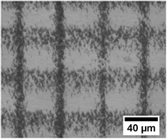
Figure 1. An optical micrograph of a silver nanoparticle deposition with non-optimal parameters.
Download figure:
Standard image High-resolution imageThe process-characterization trials lead to determining the parameters for obtaining the highest quality of deposition (i.e. well defined geometry and minimal overspray).
Figure 2(a) shows the SEM image of the deposited surface that is obtained by using the optimized LAMM parameters, as reported in table 2. The deposited lines in figure 2(a) are well defined with 20 µm width and 40 µm separating distance, as specified in the trajectory program. As the micrograph shows, the amount of overspray is very limited. The profilometry map shown in figure 2(b), the deposit forms an even and almost periodic pattern. A profilometry mapping at higher magnification is performed to evaluate more precisely the thickness of the deposited lines, figure 2(c). According to the color scale used for the z dimension, the deposit thickness varies between approximately 100 nm to 1 µm along a single line.
Table 2. Optimized LAMM process parameters.
| Parameter | Value |
|---|---|
| Atomizer gas flow rate (cm3 · min−1) | 20 |
| Sheath gas flow rate (cm3 · min−1) | 48 |
| Ultrasonic atomizer voltage (V) | 50 |
| Deposition velocity (m · s−1) | 0.7 |
| Deposition tip diameter (µm) | 150 |
| Hot plate temperature (°C) | 80 |
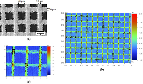
Figure 2. A deposition obtained using the parameters reported in table 2: (a) a secondary electron SEM image, (b) and (c) profilometry maps.
Download figure:
Standard image High-resolution image3.1.2. Laser heat treatment.
The deposition step is followed by a laser heat treatment, which is applied to the entire surface. The goal of this process is to obtain an early stage of sintering (i.e. necking) of the nanoparticles, so that the nano-scale topography of the sintered deposit is preserved. A systematic sequence of altering the laser scanning speed and characterizing the surface by SEM is conducted to achieve the desired sintering characteristics.
As illustrated by figure 3(a), the laser treatment using 8 W power and a scanning speed of 0.1 m · s−1, results in an advanced state of sintering with particles completely bonded together. Using the same laser power but changing the scanning speed to either 0.2 or 0.3 mm · s−1, figures 3(b) and (c), leads to an early stage of sintering where necking between particles has begun but the surface topography has still nano-scale characteristics. By further increasing the velocity to 0.4 mm · s−1, figure 3(d), the degree of necking between nanoparticles does not seem to be highly impacted. Thus, a laser power of 8 W and speed of 0.25 mm · s−1 has been chosen in order to obtain desirable sintering condition.
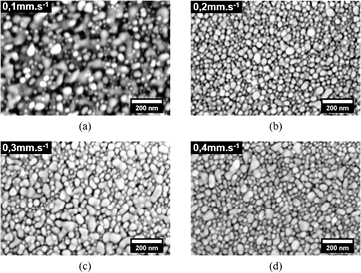
Figure 3. SEM images of the sintered deposits using 8 W power and different laser scanning velocity: (a) 0.1 mm · s−1, (b) 0.2 mm · s−1, (c) 0.3 mm · s−1 and (d) 0.4 mm · s−1.
Download figure:
Standard image High-resolution image3.2. Impact of the laser on the substrate microstructure
A sample processed with the parameters listed in table 2 and a laser speed of 0.25 mm · s−1, is characterized to examine the impact of the laser processing on the microstructure of the substrate. A cross section is obtained by FIB cutting, figure 4(a). The microstructure of the silver deposit layer and the substrate are shown in figures 4(b) and (c).

Figure 4. (a) FIB sectioning area, (b) and (c) backscattered electron images of a cross-section of a silver nanoparticles deposited and laser treated sample with two different magnifications. The substrate shows Mg grains (dark contrast), along with Mg2Ca particles (the brightest contrast). Please refer to [29] for TEM and electron diffraction analysis of the particles.
Download figure:
Standard image High-resolution imageFigures 3(c) and 4(b) show that the silver layer has achieved relatively homogeneous necking between particles across the layer. We note that, though it has been possible to cut a FIB section, the interface between the silver deposit and the substrate shows however some de-cohesion. The microstructure of the substrate consists of magnesium grains and Mg2Ca particles. The grain size varies from less than 1 µm in a thin (~1 µm) layer below the surface (referred to as sublayer) to several microns well below the surface. Mg2Ca particles also vary in size with micro-size particles distributed in the substrate below the sublayer. These microstructural features suggest that the bulk substrate retains the structure of the as-extruded material [29], while the sublayer is affected by the surface deposition process.
To better understand the effect of the deposition process on the sublayer, a cross section, using FIB cutting, is prepared from a location of the sample free of deposition (the location lies in between to deposit lines), figure 5(a). The TEM analysis, as shown in figure 5(b), shows that the sublayer of small grain also exists in this region. A crystallographic mapping at the vicinity of the surface (as specified in figure 5(b)), using ASTAR and the classical crystallographic orientation code, is displayed in figure 5(c). The ASTAR study clearly indicates that there is a 1 µm thick sublayer formed by small grains ranging in size from about 100 nm to 500 nm, with the smallest grains located the nearest to the surface. These findings indicate that the formation of the sublayer is independent of the silver deposition process. The ASTAR mapping also shows that the sublayer grains are not elongated, i.e. have no preferential orientation and show no sign of a high dislocation density or twins. The grain boundaries appear with well-defined edges and large misorientation angles. Associated with the TEM study, EDS is used to obtain the compositional profile along the cross-section. The results show no evidence for the diffusion of silver in the substrate.
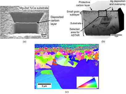
Figure 5. (a) SEM image of the FIB cutting location of a sample that has been laser processed according to the parameters listed in table 2; (b) a bright field TEM image of the FIB cut sample; (c) the associated ASTAR mapping of the selected area, as shown in (b).
Download figure:
Standard image High-resolution image3.3. 3D finite element modelling
A 3D thermal model has been developed using COMSOL Multiphysics. It aims to simulate the thermal effect of a laser source scanning a substrate which is held at a constant temperature. This is achieved by the numerical modelling of the local temperature as a function of time and depth in the materials (i.e. deposit and substrate). Figure 6 shows the front view of the domain of the silver deposition, which is 200 µm long, 20 µm wide and 1 µm thick.

Figure 6. Mesh plots of the model with a focus on the front view of the deposition.
Download figure:
Standard image High-resolution imageThe following equation is considered for governing heat transfer in the solid:
where ρ, Cp, k and Q are, respectively, the density, the specific heat capacity, the thermal conductivity and the power generation per unit volume. The heat transfer module and the boundary conditions used in Jabari et al [30] were adapted to solve the heat transfer equation.
In the present study, the effect of temperature on properties is considered negligible. Therefore, three different boundary conditions were implemented for this semi-infinite domain: the convective heat transfer, the moving power input and the constant temperature of the bottom of the substrate.
The convective heat transfer is applied to all surfaces except the bottom facet. In these cases, the boundary condition is given by:
where n is the normal vector to the surface boundary, Q is the heat flux from the laser beam and hS is the convective heat transfer coefficient associated to the corresponding surface. At the laser beam location, the moving power input is then applied as a boundary condition. Thus, the moving power input is given by:

where  is the absorption coefficient of the material (substrate or silver deposition). The laser intensity distribution, characterized by a TEM00 transverse mode, is given by:
where Pl, M2, rl and r are respectively the laser power, the beam factor quality, the spot size at the process zone and the distance from the center of the spot size. As the laser beam is moved on the substrate surface at a defined velocity, vl, the distance from the center of the sport size can be written as follows:

where  is the Cartesian coordinates of the center of laser beam at t = 0 and vl is the velocity of the laser beam.
Following Foroozmehr et al [27], the silver deposit is described as a porous material made of packed silver nanoparticles with a layer thickness of 1 µm. According to Dullien et al [31], the porosity for a random packing of spheres is approximately 37.5%. Thus, the density of the silver deposition is considered equal to 6563 kg · m−3. For simplification, the porosities in the deposition are considered spherical. According to Cernuschi et al [32], using this assumption, the thermal conductivity can be calculated as follows:

where ks and φ are, respectively, the thermal conductivity of silver and the ratio of porosities.
In addition, due to the small size of the silver nanoparticles (≈60 nm), the roughness of the deposition has an impact on its absorbance [33]. According to Bennett et al [34], the effective absorbance due to the roughness of the material can be determined using the following expression:

where A is the absorbance of the material, δ is the root mean square (RMS) roughness and λ is the wavelength of the incident beam. Considering the surface as an array of spheres, δ is assumed to be equal to 60 nm. Concerning the substrate absorbance, the measured RMS roughness for polished samples is approximately 0.2 µm which is of the same order as the laser beam wavelength. Thus, it was assumed that the impact of the roughness of the substrate on its absorbance is negligible.
Finally, by using the previous assumptions and literature [35–37], we obtain the parameters summarized in table 3.
Table 3. A summary of the material characteristics [35–37].
| Material | Thermal conductivity (W · m−1 · K−1) | Density (kg · m−3) | Specific heat capacity (J · kg−1 · K−1) | Absorbance |
|---|---|---|---|---|
| Substrate (Mg-2wt.%Ca) | 122 | 1736 | 1008 | 0.23 |
| Deposition (silver) | 209 | 6563 | 244 | 0.23 |
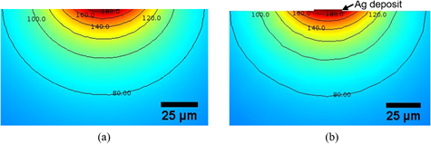
Figure 7(a) displays the cross section of the temperature maps at the center of the laser beam focused on the sample surface in two cases: without deposition, figure 7(a), and with a silver deposition on the substrate, figure 7(b).
Figure 7. Temperature maps in the vicinity of the laser beam center for the substrate (a) without deposition or (b) with silver deposition.
Download figure:
Standard image High-resolution image
According to the simulation, a thin layer substrate is significantly thermally affected by the laser treatment: 180 °C is reached at the first micrometer below the surface. The temperature rapidly decreases with the thickness of the substrate. Also we can conclude that the silver deposition has a negligible impact on the temperatures in the substrate.
4. Discussion
Although the optimization of process parameters in this work has resulted in the desired surface deposition with suitably sintered silver nano particles, the localized decohesion between the deposit and the substrate needs to be addressed. This decohesion is suggested to occur due to the evaporation of the solvent (ethylene glycol) trapped at the deposit-substrate interface during the laser treatment. Considering the boiling point of ethylene glycol (197 °C) and the temperature profile obtained from the FEM calculations, this conclusion is plausible. To eliminate this problem, it is suggested that the silver nanoparticles deposited work piece is suitably heated (e.g. using the same hot plate that is utilized during the deposition to improve the wettability), so that ethylene glycol is evaporated prior to the laser heat treatment process. One can also note that in the present study, the thickness of the deposition varies between 100 nm and 1 µm. A more diluted solution and adapted LAMM parameters may be used to reduce the thickness range of the deposition. However, such a solution could rapidly increase the time of the deposition process when several depositions or a slow deposition velocity are needed. For future studies when several layer of depositions are needed, it is suggested to evaporate the solvent between successive depositions.
The experimentally-observed grain size gradient in the substrate is usually related to the thermomechanical history of the material. The as-extruded Mg-2wt.%Ca alloy substrate has a recrystallized material with an average grain size around 8 µm and particles of second phase ranging between 1 to 14 µm [29], matching the observations made from the current substrate in depths below the fine-grained sublayer. The microstructure of the sublayer, as described in section 3.2, is in agreement with a recrystallized microstructure, though very different from the as-extruded material. Thus, the fine-grained sublayer should result from the recrystallization of a locally-deformed substrate surface during the laser treatment. The heating profile obtained from the FEM simulation of the laser treatment is in agreement with a thermally-activated process at the sublayer, as well. Considering the entire sample preparation history, it is reasonable to conclude that the sample polishing process prior to silver deposition has caused localized deformation at the surface region. This conclusion is also in agreement with previous reports on work hardening and grain refinement at the surface of polished metals [38, 39].
Interestingly, the formation of the current fine-grained sublayer also suggests that surface polishing may be employed in processing Mg–Ca alloys for biomedical applications to improve their initial corrosion resistance [40]. The initial corrosion resistance of the silver nanoparticles deposited Mg-2wt% Ca alloy is expected to depend on the galvanic effect between silver and the fine grained structure of the substrate in silver-free regions, as well as other relevant factors. The corrosion study of this system, however, is beyond the scope of the current work.
5. Conclusions
The present study has outlined a processing method for a controlled deposition of silver nanoparticles on a magnesium alloy substrate using the LAMM technique and laser sintering it for desirable nano-to-micro scale topography and particle cohesion. An FEM simulation method has also been implemented to study the thermal impact of the laser treatment process on the magnesium substrate. In addition, optimized deposition conditions have been determined for patterning a magnesium substrate with silver nano-particles using the LAMM technique. Using these conditions, it has been possible to obtain reproducible deposition of 20 µm width crossed lines with line thickness ranging between few hundreds of nanometers and one micrometer. Finally, a continuous laser heat treatment has been used in order to obtain multiscale topography on the silver deposited surface. This treatment has been optimized in order to obtain an early stage of sintering which permits to keep the nanotopography of the silver nanoparticles at the surface of the deposited layer.
Owing to microstructural investigations on a cross section, it has been revealed that the utilized laser treatment leads to microstructural evolution in the magnesium substrate. The thermally affected zone consists of a fine-grained sublayer of about 1 µm below the surface, which originates from the mechanical polishing of the surface prior to deposition. The thermal evolution of the substrate under the laser heat treatment has been addressed by an FEM simulation that concludes to a significant thermal impact in the vicinity of the surface. However, according to the microstructural observations, it appears that only a thin layer of the substrate (in the order of 1 µm) is thermally affected by the laser treatment process. The acquired knowledge can be of interest in the future designs of microstructurally-engineered and laser-processed Mg substrates for biodegradable device applications.
Acknowledgments
The authors would like to acknowledge the IDS FunMat and NSERC Discovery of Canada for the direct financial support of the research and CanmetMATERIALS for providing the Mg alloy used for the investigation. This work was performed within the framework of the Association of Scientific Interest on architectural materials (Groupement d'Intérêt Scientifique—GIS) and the Centre of Excellence of Multifunctional Architectured Materials 'CEMAM' No. ANR-10-LABX-44-01. The help received from Mr Andrew Michael from the Center for Advanced Materials Joining at the University of Waterloo and from Mr Frederic Charlot from the Consortium des Moyens Technologiques Communs (CMTC) is highly appreciated.