

Abstract
This paper describes a microfluidic multicolor display utilizing juxtapositional color mixing of pixels. Our display has a 14 × 14 array of pixels (2.5 mm in pixel diameter, 8.46 ppi) on the display surface where multicolor is expressed by controlling the pattern of the four primary color inks (cyan (C), magenta (M), yellow (Y), and black (= key plate, K)) that fill the pixels. The microfluidic display has a three-layer structure composed of a top layer with pixels for displaying images, a middle layer that serves as a background screen, and a bottom layer with microchannels that connect the pixels. In order to express multicolor by combining CMYK primary colors, we optimized the concentration of the inks used as the primary colors. By designing patterns of pixels filled with CMYK ink, color gradations and multicolor images were displayed on our display. The proposed microfluidic display could be applied to eye-friendly and low-energy-consumption flexible display applications including multi-purpose sign boards used in outdoors, wearing objects, and exterior/interior of vehicles and architects.
Export citation and abstract BibTeX RIS
1. Introduction
In the information society, display devices that are one of the most famous information and communications technologies, are essential as a means of disseminating information to others immediately and widely. Commonly, those display devices are classified into two categories based on their display principles: light-emitting displays and reflective displays [1–4]. While light-emitting displays have a light source and emit light directly from the display surfaces, reflective displays do not have a light source, but reflect ambient light to users. Thanks to the absence of a light source, reflective displays are attracting attention as eye-friendly and eco-friendly devices that generate less blue light [5, 6] and consume less energy than light-emitting displays. One example of reflective displays is an electrophoretic display for commercially available electronic paper [7, 8]. These electrophoretic displays can keep the screen without energy but are limited to show only black-and-white images. Another example is an electrowetting display for the color filter and smart watch [9–11]. The electrowetting displays can show color images, but they require energy to keep the displayed images on the screen.
On the contrary, a microfluidic display, which is one emerging type of reflective display and uses stained fluid (ink) as the display element, requires no energy to keep the screen and shows colorful images using multiple stained fluids [12–14]. Generally, microfluidic reflective displays are composed of a couple of meandering microchannels fabricated in a two dimensional plane [12, 13] or fluidic tubes wrapped on an object [14]. Prior reports have demonstrated that those microfluidic displays can show colored characters and images by introducing one type of colored ink in each single microchannel [13, 14]. Furthermore, the microfluidic display can show not only optical information using pigment colors [12–14] or structual colors [15], but also thermal information using the desired temperature fluid [12]. For these advantages, the microfluidic display has researched vigorously in recent years. However, important issue to be solved is that those microfluidic display requires numerous colored fluids to show multicolored images; that is, the number of displayed colors depends on the number of colored fluids. Thus, the increase in the number of displayed colors on the microfluidic display causes the complexity of the display system. These problems hinder the realization of high quality and colorful images on the microfluidic display.
Here, we propose a microfluidic reflective display that expresses multicolor by juxtapositional color mixing (Juxtaposed mixed-color Microfluidic Multicolor Display, JMMD) (figure 1(a)). Numerous colors can be displayed only by using the four primary colors, cyan (C), magenta (M), yellow (Y), and black (= key plate, K) arranged on the JMMD display. The JMMD consists of four three-dimensional (3D) microchannels that have cylindrical chambers (pixels) and connective channels. The pixels are filled with CMYK ink or air (as blanks) to express the color image on the JMMD by controlling the introduced ink pattern. Variation of color expression on the JMMD is tuned just by the combination and spatial density of the primary color ink pixels without preparing color variations of inks (figure 1(b)). Multicolors are expressed by increasing the fill ratio of the pixels and controlling the combination of primary color pixels. In this study, we optimize the concentration of the ink used as the primary color, and display juxtapositional color mixing with CMYK inks on the JMMD. Multicolor (color gradation) expression on the JMMD is evaluated with Hue, Saturation-Chroma and Value-Brightness (HSV) color chart and color gamut, and multicolor images are finally displayed as a demonstration.
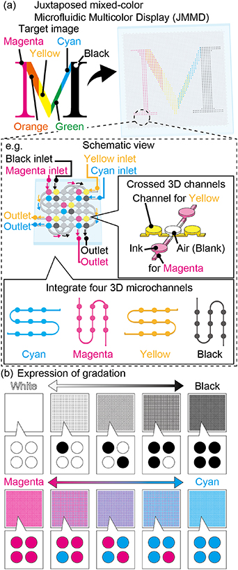
Figure 1. Conceptual illustration of Juxtaposed mixed-color Microfluidic Multicolor Display (JMMD). (a) Principle of displaying a multicolor image on the JMMD, and schematic view of the JMMD structure. The JMMD has four independent 3D microchannels. (b) Sample images of color gradation on the JMMD. Multicolor is expressed by positioning the inks that fills the pixels.
Download figure:
Standard image High-resolution image2. Design of the JMMD
Figure 2(a) shows the general design and dimensions of the JMMD. Cylindrical chambers (pixels) are arranged in a 12 × 12–14 × 14 square array in the display surface. The JMMD has a three-layer structure to build the 3D microchannels (figure 2(a) side view). The top layer serves as the screen surface for displaying the images. The pixels used for displaying images are located at the top layer and are connected to through holes in the middle layer. The middle layer plays the role of connecting the top layer and the bottom layer via through holes. In addition, the middle layer is colored in white (non-transparent) to serve as the background screen of the display that optically hides the microchannels in the bottom layer. The bottom layer has microchannels that connect pixels in the x-axis direction or y-axis direction in every other pixel. Thus, as shown in the detail view (figure 2(a) top right), four different-color ink solutions are arranged as pixels in a two-dimensional plane. The resolution of the JMMD is 1 pixel/3 mm = 8.46 ppi where the diameter of the pixel is 2.5 mm and the distance between the pixels is 0.5 mm. The pressure drop in the JMMD design is estimated to 5.45 Pa at flow velocity of 1.0 × 10⁻³ m s−1 (detailed tehory is described in supporting information 1 (available online at stacks.iop.org/JMM/32/025002/mmedia)).
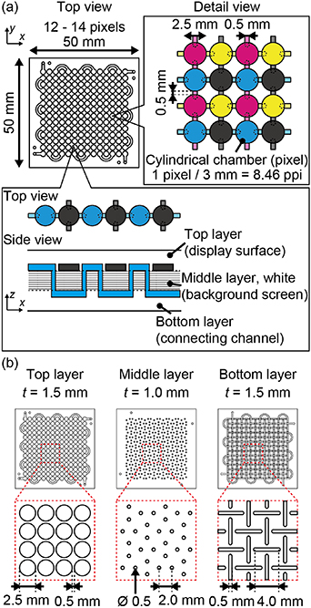
Figure 2. The design and dimensions of the JMMD. (a) The design of the JMMD pixels and the structure of 3D microchannels. The JMMD is a three-layered structure, and the pixels are connected in x-axis or y-axis direction in every other pixel by the connecting channel in the bottom layer. (b) The design drawing of the top, middle, and bottom layers.
Download figure:
Standard image High-resolution imageFigure 2(b) shows the design drawing of the top, middle, and bottom layers. The top layer is 1.5 mm thick, and the pixels are 1.0 mm thick. The middle layer is 1.0 mm thick, and the diameter of the through hole is 0.5 mm. The bottom layer is 1.5 mm thick, and the microhannels of 0.5 mm width and 4 mm length are aligned in the x-axis and y-axis directions.
3. Experimental methods
3.1. Fabrication of the JMMD
The JMMD was fabricated by a PDMS mold-replica method and a bonding process (figure 3(a)). First, three aluminum molds (top, middle, and bottom layers) with microchannel patterns were prepared by machining (figure 3(i)). The PDMS base polymer and curing agent (Dow Corning Toray Co., Ltd, Silpot 184) were mixed in a ratio of 10:1 to obtain the mixed PDMS prepolymer solution. The prepolymer solution was poured into the top and bottom layer molds. For the middle layer, calcium carbonate powder (Wako Co., 030-00385) was added to the mixed PDMS prepolymer solution at a ratio of 1:10 and suspended by a planetary centrifugal mixer (THINKY Co., ARE-250) to obtain white-colored PDMS prepolymer solution. The mixed white PDMS prepolymer solution was poured into the middle layer mold. The PDMS poured into the aluminum molds was thoroughly degassed in vacuum (figure 3(ii)).
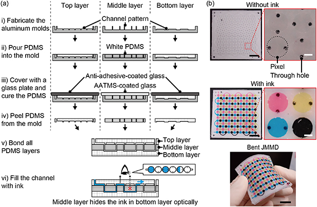
Figure 3. The fabrication process of the JMMD. (a) PDMS molding and bonding process for top, middle, and bottom layers. The PDMS of the top and bottom layers are transparent, and the PDMS of the middle layer is white colored. (b) Photographs of the fabricated JMMD with/without ink filling the pixels. Scale bars: 10 mm ((b) whole views, black lines); 1 mm ((b) close-up views, white lines).
Download figure:
Standard image High-resolution imageFor the lids of the top and bottom layer molds, glass plates (Matsunami Glass Ind., Ltd, S9111) were coated with anti-adhesive reagent (Optool, DAIKIN Ind., Ltd, HD-1100TH) by dipping and heated at 100 °C for 5 min. For the lid of the middle layer mold, a glass plate was immersed in the 2% w/w solution of the 3-(2-aminoethyl)-aminopropyltrimethoxysilane (AATMS, Dow Corning Toray Co., Ltd, OFS-6020) in methanol (Wako Co.) for 1 h and baked in an oven at 100 °C for 10 min to prevent the PDMS prepolymer from curing on the glass surface [16, 17]. The top and bottom molds with PDMS prepolymers were covered with the anti-adhesive-coated glass plates, and the middle mold with white-colored PDMS prepolymers was covered with the AATMS-coated glass plates (figure 3(iii)). After heating at 75 °C for 90 min, the PDMS layers were peeled off from the aluminum molds (figure 3(iv)).
All the PDMS layers were bonded by air plasma bonding (MEIWAFOSIS Co., Ltd, SEDE-P). Diluted inks (Cyan, Magenta, Yellow, Black, BROTHER Ind., Ltd, Br-Ink100-4K-2) were injected into the channels without surface treatment (figures 3(v) and (vi)). Since the middle PDMS layer was white colored, the injected ink in the channels at the bottom PDMS layer were optically hidden from the top view. Thus, the injected inks in the cylindrical chambers in the top layer were only displayed as pixels.
3.2. Optimizing ink concentration
On the JMMD, multicolor was expressed by juxtapositional color mixing of pixel patterns of cyan (C), magenta (M), yellow (Y), or black (K). We compared variously diluted CMYK inks introduced in the JMMD to color references for evaluating the color expression: Cyan, magenta, and yellow inks diluted to 10.0%, 5.0%, 1.1%, 1.0%, 0.9%, 0.5%, and 0.1% with pure water, and black ink diluted to 90.0%, 80.0%, 70.0%, 60.0%, 50.0%, 40.0%, 30.0%, 20.0%, 10.0%, 5.0%, and 1.0% with pure water were tested. The pixels filled with these diluted ink solutions and color reference charts (Japan Paint Manufactures Association, Standard Paint Colors Pocket Type, munsell color value 10B5/10 as cyan, 5RP5/12 as magenta, 5Y8.5/12 as yellow, N1 as black) as references for the primary colors were placed side by side, and photographs were taken with a digital camera (Olympus Co., Tg-5) (figure 4(a), detailed images are in supplementary figure S2). The L* a* b* values (a type of coordinate value in color space [18–20]) for the ink-filled pixels and the color references was measured by the image processing program (ImageJ, Lab stack and Histogram). By using the average values of the measured L* a* b*, the color difference ( ) [21, 22] between the color chart and the pixels was calculated for CMYK colors (see supporting information 3 for a detailed derivation of the color difference).
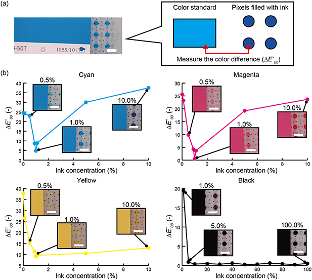
Figure 4. Optimizing the concentration of CMYK inks used as primary colors on the JMMD. (a) Conceptual diagram of the experiment. (b) The relationship between ink concentration and the color difference ( ). The minimum value of
  shows the optimal ink concentration. Scale bars: 5 mm (a) and (b).
Download figure:
Standard image High-resolution image3.3. Displaying color gradation by combination of primary colors
As a single color gradation, the JMMD was filled with the optimized CMYK inks at fill ratio of 25% (one fourth of all the pixels in the display was filled), 50% (half of the pixels), 75% (three forth fo the pixels), and 100% (all pixels). As a dual color gradation, the JMMD was filled with the cyan and magenta (C-M), magenta and yellow (M-Y), yellow and cyan (Y-C), cyan and black (C-K), magenta and black (M-K), yellow and black (Y-K) inks. The fill ratios of 75%:25%, 50%:50%, and 25%:75% were examined for all six dual color gradations. The JMMD with the inks was photographed by a digital camera (Olympus Co., Tg-5, Macro mode, white balance: white fluorescent light (4200K)) under ambient light environment in a laboratory. The obtained images were black-balanced with an image processing software with (Adobe, Photoshop). The distribution of HSV of the entire display surface was measured by ImageJ (NIH). The averaged values of the measured HSV under each color variations of the JMMD were shown with computational colors converted from HSV by an illustration software (Adobe, Illustrator). The averaged values of the HSV were used to express the color gamut of the dual color gradations using C-M, M-Y and Y-C on a H-S color circle and those using C-K, Y-K and M-K on a S-V plane.
3.4. Display of color images with juxtapositional color mixing
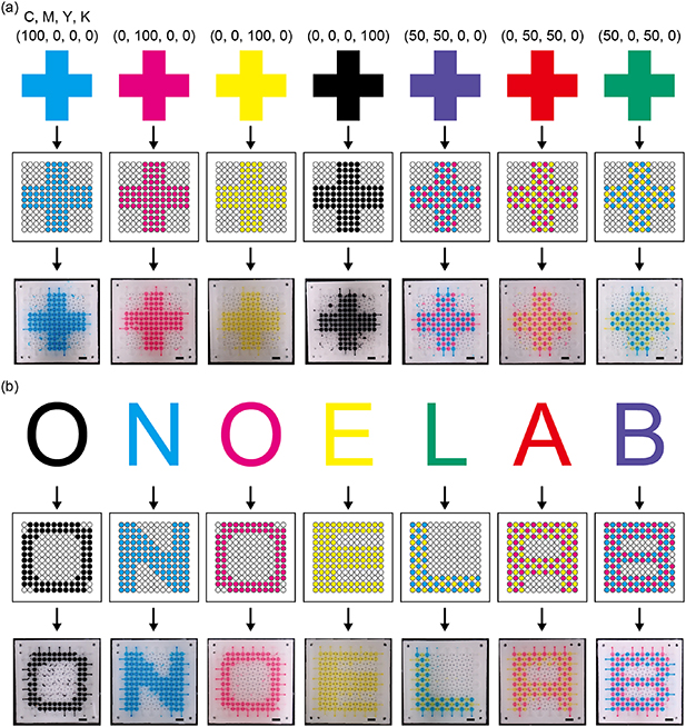
As a demonstration, color images were shown on the JMMD. From the experimental results of the ink concentration optimization, 1% ink concentration for cyan, magenta and yellow, and 5% ink concentration for black were used for the JMMD. A '+' symbol was designed on the pixel array. According to the designed pixel patterns, the inks and air (as blanks) were injected into the channels to display the image. In the case of filling the channel with ink, the ink solution was dropped on the inlet hole and sucked with a syringe from the outlet hole. In the case of introducing the air into the channel, the ink was removed from the inlet hole before sucking with the syringe. For example, to fill pixels with a pattern of 2 inks-4 blanks-2 inks, ink was dropped on the inlet and sucked from the outlet for 2 pixels, then, ink was removed from the inlet and sucked for 4 pixels, and ink was dropped on the inlet again and sucked from the outlet for 2 pixels. The process of selective ink and air injection was performed manually. A '+' symbol was displayed at various fill ratios of the ink: cyan (CMYK:100, 0, 0, 0), magenta (CMYK:0, 100, 0, 0), yellow (CMYK:0, 0, 100, 0), black (CMYK:0, 0, 0, 100), violet (CMYK:50, 50, 0, 0), orange (CMYK:0, 50, 50, 0), and green (CMYK:50, 0, 50, 0). In the same way, characters were displayed on JMMD with the following conditions: 'O' (CMYK:0, 0, 0, 100), 'N' (CMYK:100, 0, 0, 0), 'O' (CMYK:0, 100, 0, 0), 'E' (CMYK:0, 0, 100, 0), 'L' (CMYK:50, 0, 50, 0), 'A' (CMYK:0, 50, 50, 0), and 'B' (CMYK:50, 50, 0, 0). The JMMD with the color image was photographed by a digital camera (Olympus Co., Tg-5, Macro mode, white balance: white fluorescent light (4200 K)) under ambient light environment in a laboratory. The obtained images were black-balanced with an image processing software (Adobe Photoshop).
4. Results and discussion
4.1. Fabricated the JMMD
Our JMMD had 14 × 14 pixels in a 2D display surface at 8.64 ppi resolution, composed of four different 3D microchannels for each CMYK color in the three-layer PDMS sheet (figure 3(b)). When the JMMD was not filled with ink (initial state) (figure 3(b), top), the white PDMS (background screen) was visible. A close-up view showed the array of cylindrical chambers (pixels) in the top layer and the through holes in the middle layer. From the image filled with optimized CMYK ink (figure 3(b), bottom) showed that each of the cyan and yellow pixels was connected in the x-axis direction, and each of the magenta and black pixels was connected in the y-axis direction in every other pixel. The middle layer worked as a background screen because the ink filled in the microchannels at the bottom layer was optically hidden by the middle layer. Since the JMMD was made of soft material (PDMS), the JMMD was highly flexible. The ink array remained stable even when the JMMD filled with ink was bent, indicating that the JMMD could be applied to as a flexible display (figure 3(b) bottom).
4.2. Color difference between ink and color reference chart
The color expression on the JMMD was determined by the coloring of CMYK inks introduced in the microchannel. Thus, the concentration of the CMYK inks were optimized by comparing the color difference ( ) between the diluted CMYK inks and the color reference chart (figure 4(a)). From the photos of the cyan optimazation experiment (figure 4(b), cyan), the pixels filled with 10% concentration ink had a darker blue color than the color chart (figure 4(b), cyan, right inset). On the contrary, pixels filled with 0.5% concentration ink had a lighter blue color than the color chart (figure 4(b), cyan, left inset). Therefore, cyan at 10% and 0.5% concentration had a larger color difference value from the color chart (
 = 37.5 at 10%,
  = 23.0 at 0.5%). The graph of cyan (figure 4(b), cyan) showed that the cyan ink concentration closest to the color chart was determined to be 1% (
 = 4.8). For magenta and yellow (figure 4(b), magenta and yellow),
  showed the minimum value when the concentration was 1%, meaning that the ink concentration closest to the color chart was 1% (
 = 0.5 at magenta,
  = 9.0 at yellow). In the case of black (figure 4(b), black), there was no significant difference in the values of
  from 100% to 5% ink concentration, but the value of
  was high at 1% concentration. Therefore, black can be used as the primary color with any concentration of ink as long as the ink is not too diluted. From the above, the optimal ink concentrations for CMYK pixels were determined to be 1% for cyan, magenta, and yellow, and 5% for black. These ink concentrations determined by the optimization experiment were used in the subsequent experiments.
4.3. Color gamut of display by combining primary colors
Firstly, color graduation expressed on the JMMD was investigated by introducing a single color ink with different fill ratios (spatial density of the colored pixels). The single color gradation expressed on the JMMD (figure 5(a), left) shows that the expressed colors became more vivid as the fill ratio increased. In the case of cyan, the hue (H) and value (V) remained constant (H was around 200, and V was around 80), while the saturation (S) increased from 28 to 83 as the fill ratio increased (figure 5(a), right). The saturation of magenta increased from 23 to 54 and that of yellow from 22 to 55. In the case of black, the hue and saturation remained constant (H was around 290, and S was around 7), and the value decreased from 62 to 29. Therefore, the saturation control of CMY and the value control of black were achieved by changing the spatial pixel fill ratio.

Figure 5. Color gradations expressed on the JMMD by controlling the pixel fill ratio. (a) Resulting photos of the single color gradation, and HSV values of the gradations with computational colors converted from HSV values. (b) Resulting photos of the dual color gradation (C-M, M-Y, and Y-C), and HSV values with computational colors. The right graph shows the color gamut on the H-S color circle expressed on the JMMD using CMY inks. (c) Resulting photos of the color gradation with black (C-K, M-K, and Y-K), and HSV values with computational colors. The graphs show the color gamut on the S-V plane expressed on the JMMD using CMY and K inks. Scale bars: 10 mm.
Download figure:
Standard image High-resolution imageMulticolor expression by juxtapositional color mixing on the JMMD was next evaluated. The dual color gradation of cyan, magenta and yellow was created on the JMMD and analyzed with HSV value (figure 5(b)). From the measured HSV values, the combination of two different colors mainly dominated the hue of the colors displayed on the JMMD (figure 5(b), left). In the nine conditions, saturation and value showed little variation (the S value was 57.0 ± 5.1, and the V value was 80.6 ± 4.6 (figure 5(b), center)), while the hue changed in sequence (H varied from 9, 25, 71, 144, 183, 225, 263, 308, and 354 for conditions M:Y = 50:50 (middle of the color chart), M:Y = 25:75, Y:C = 75:25, Y:C = 50:50, Y:C = 25:75, C:M = 75:25, C:M = 50:50. C:M = 25:75, and M:Y = 75:25). Therefore, by using the JMMD, combination of only three types of inks (CMY) can express the wide range of colors in the Hue. The distribution of the colors expressed by the combination of cyan, magenta, and yellow was expressed on the H-S color circle (figure 5(b), right). The plot area (dotted line circle) means the color gamut that was expressed on the JMMD, thus indicating that the JMMD can express 360-degree color tones in stages.
The dual color gradation with black (C-K, M-K, and Y-K) on the JMMD (figure 5(c)) shows that the colors became darker as the fill ratio of black increased. From HSV values, the decreases in S and V was confirmed as the fill ratio of black increased. (in the case of cyan, S decreased from 70 to 35, and V decreased from 72 to 46. In the case of magenta, S decreased from 45 to 20, and V decreased from 83 to 45. In the case of yellow, S decreased from 42 to 15, and V decreased from 69 to 44). The color distribution plots on the S-V plane (figure 5(c) bottom) means that the fill ratio of black can design the S and V of the color displayed on the JMMD in stages. Thus, the HSV of the colors displayed on the JMMD can be designed by controlling the fill ratio of the primary colors (CMYK).
4.4. Display of images and characters
Finally, the color images and characters with juxtapositional color mixing were displayed on the JMMD as demonstrations (figure 6). Based on the illustrated design of the color images of the '+' in various CMYK ratios (figure 6(a), top), the pixel patterns were generated with converted CMYK proportions (figure 6(a), middle). The '+' symbols displayed on the JMMD with the generated pixel patterns (figure 6(a) bottom) shows that the same pixel pattern as the designed pixel pattern was displayed on the JMMD for each color. The '+' signs that were 50% cyan and 50% magenta, 50% magenta and 50% yellow, and 50% yellow and 50% cyan, were visually observed as violet, orange, and green, respectively, by juxtapositional color mixing. Therefore, the JMMD displayed images with a wide range of color variations. Examples of alphabetic characters, 'ONOELAB.' were also demonstrated on the JMMD to confirm the capability of the displayed image variations on the JMMD (figure 6(b)). Therefore, in principle, arbitrary color images can be displayed on JMMD by designing the pixel pattern of the desired color image.
Figure 6. Color images displayed on the JMMD with juxtapositional color mixing. (a) Multicolor '+' symbols on the JMMD. The target color images are shown at the top, the pixel pattern converted from the target images at the middle, and the color images displayed on the JMMD at the bottom. (b) Multicolor 'ONOELAB' characters displayed on the JMMD. Scale bars: 5 mm (a) and (b).
Download figure:
Standard image High-resolution image
4.5. Discussion for practical use
We proposed the microfluidic multicolor display using only four primary colors (JMMD) to demonstrate multicolor expression using juxtapositional color mixing on the JMMD. There have been several reports on microfluidic displays that express multicolor [13, 14], but the expressed colors on the reported displays limited to the colors of the inks used in the displays. Thus, the previous microfluidic displays required to prepare many different inks to display multicolor images. In addition, switching between those multiple inks introduced into the microchannels or mixing of the different colors in the pixels was essential for the previous microfluidic displays, causing the complexity of display systems. On the other hand, the proposed JMMD achieved the expression of color gradations by simply controlling the fill ratio of the pixels, not the ink variations. This indicates that the fluid control system required for the JMMD could be very simple, and that the JMMD overcomes one of the factors that hindered the practical application of microfluidic displays.
The JMMD is the first microfluidic display that has multi-color expression function by juxtapositional color mixing. Juxtapositional color mixing is a widespread color display method in commercial optical displays (e.g. PC, smartphone) [23, 24]. A typical light-emitting display consists of light-emitting elements of red, green, and blue, the three primary colors of light. However, while additive color mixing is used for the light-emitting displays, subtractive color mixing [25] must be used for the reflective displays because the reflective displays do not emit light themselves [26–28]. Therefore, cyan, magenta, and yellow, the three primary colors of color, are suitable as a display element for reflective displays.
Generally, display resolution dominates the color quality in a multicolor expression method based on the principle of juxtapositional color mixing. Juxtapositional color mixing with CMY is used in the printing technology of commercial inkjet printers. Inkjet printers print in color by juxtaposing minute circular patterns of cyan, magenta, and yellow (on the 1 μm order) [29, 30]. Therefore, the JMMD shows multicolor in a similar way in principle to current printing technology. The JMMD proposed in this paper has 2.5 mm diameter pixels and 8.46 ppi resolution. Because typical commercial display resolutions are around 100–300 ppi, smoother juxtapositional color mixing could be achieved on the JMMD by downsizing the pixel size of JMMD to around 100 μm. In addition, the color quality is also affected by ink misalignment. For example, in figure 6, ink had been trapped in some of the pixels that should be blanks. In the previous study, the trapped ink was suppressed by controlling the pixel shapes [13]. Therefore, downsizing the pixel size of the JMMD and optimizing the pixel shapes would improve the color quality of the JMMD.
As an alternative approach to increasing the resolution, large area displays such as multi-purpose sign boards used in outdoors, wearing objects including cloths, and exterior/interior of vehicles or architects are possible applications of the JMMD without high pixel resolutions. For the human eye, optical resolution is determined by a minimum distance where two points can be separated and perceived: If two points that are closer together than that minimum distance is not recognized separately [31]. For example, when you look at photographic mosaic art [32, 33] from close up, each photo image (a single pixel ) can be recognized. But when you look at the art from a certain distance, photo images appears to be one illustration. This displaying method stems from the fact that the principle of juxtapositional color mixing utilizes the limits of the resolution of the human eye. Thus, large area displays with the proposed pixel design of the JMMD could open a new way to innovative and low-energy-consumption applications that have not been realized with light-emitting displays.
5. Conclusion
We proposed the microfluidic multicolor display by juxtapositional color mixing (JMMD). The JMMD expresses multicolor by simply controlling the pixel patterns of the four primary colors (CMYK). By comparing the color reference chart and the inks, the optimal ink concentration for use as the primary color was 1% for cyan, magenta and yellow, and 5% for black. The color gradation of saturation was expressed on the JMMD by controlling the pixel fill ratio of a single color ink, and the color gradation of hue was expressed by combining the dual colors of CMY. The colorful '+' symbol and colorful 'ONOELAB' characters were displayed on the JMMD by juxtapositional color mixing. We believe that the JMMD could be applied to next-generation wearable displays and sign boards as a low-energy consumption and full-color reflective display.
Acknowledgment
This work was partly supported by JKA and its promotion funds from KEIRIN RACE, JKA.
Data availability statement
The data that support the findings of this study are available upon reasonable request from the authors.