

Abstract
A bristle-bot or vibrobot is a multi-legged robot made of bristles and an oscillating actuator that generates vibrations. This work presents the first demonstration of a micro-bristle-bot, with 3D-printed legs, fabricated by two-photon polymerization (TPP) lithography. The presented miniaturized bristle-bot has a weight of only 5 mg, in the size of 2 mm × 1.87 mm × 0.8 mm, and can achieve a speed up to 4 times the body length per second. A base structure with six legs is fabricated by TPP direct laser writing in a single fabrication step, allowing for rapid prototyping of various leg designs. The base is attached to a 0.3 mm thick lead zirconate titanite (PZT) actuator block. The vibrational energy is provided by an external piezoelectric shaker in this work, which mimics the ocillatory behavior of the on-board PZT block. This work demonstrates the locomotion of micro-bristle-bots with various leg designs that utilizes the resonant bending mode shape at small excitation voltages applied to the external piezoelectric shaker. The presented micro-bristle-bots show a resonant frequency around 6.3 kHz, which can be tailored based on their geometry. This feature allows for addressing individual micro-bristle-bots with various geometries based on their unique resonance frequency.
Export citation and abstract BibTeX RIS
1. Introduction
Locomotive actuation of untethered, sub-millimeter, micro- or nano-sized robots has recently attracted significant attention as an emerging field [1–3]. Micro/nano-robots are reported to be promising for biomedical applications [4], micro-assembly [5], and maneuverability [6]. However, scaling down the size of traditional actuators such as electromagnetic actuators leads to complications, as electromagnetic force scales as  , where
  is the length of the actuator, and becomes inefficient in overcoming micro-scale adhesive forces [7]. Recent works on 2D traversing milli-/micro-scale robots have reported on actuators using magnetic [2, 3], optical/thermal [8], electric field [9], and mechanically amplified piezoelectric [1] actuation mechanisms, or combinations of the above [10]. However, they require external sources for actuation such as multi-axis magnetic field or lasers. Individual addressing and control of multiple micro-robots can be challenging. For instance, it is difficult to isolate individual robots in actuation fields such as magnetic [2, 3] or electric [9] fields. Furthermore, requirement of multiple optical sources becomes challenging as the number of micro-robots increases [8]. Instead, if the energy for actuation could be supplied from the micro-robot itself, they can become more independent from a central actuation source as well as from one another.
A promising solution for a simpler actuation of microrobotic systems, is the use of mechanical vibrations. Micro-robots can be designed to respond differently to actuation frequencies if they are resonantly excited. In this work, we take advantage of piezoelectric actuation that induces directional locomotion at resonance, by optimizing design of the 3D-printed vibration-driven bristle-bots. By varying the mechanical design parameters, the resonant frequency of individual bristle-bots can be distinct from one another and thus result in a highly frequency-multiplexed micro-robotics system.
A few examples of locomotion achieved by utilizing the cyclical interaction between the body and the environment have been shown in micro-scale engineered systems. A microrobot called MagPieR (Magnetic Piezoelectric Microrobot) [10] utilizes piezoelectrically induced vibrations to achieve locomotions at the speed of 71 mm s−1 with dimensions of 388 µm  388 µm
  230 µm. However, the piezoelectrically induced vibration for this microrobot was used for resisting the adhesive forces in the microscale while the main actuation was produced by the magnetic field that exerts traction force on ferromagnetic materials. Another microrobot shown in [11] with 1.5 mm
  0.7 mm
  0.2 mm dimensions utilizes kicks from a pair of legs with different resonant frequencies powered by vibrations.
Numerous examples of such locomotion mechanisms are found in nature, where high and low frictional coefficients are alternated for each half-cycle of the period of motion [12–14]. For instance, snakes use the scales on their belly to pull them forward [13] while the gastropods such as snails glide over muscus with traveling waves of their foot by sticking and sliding in different parts of the cycles [14]. In all presented cases, the stick-and-slip cycles are responsible for achieving locomotion by exploiting the dry friction or rheology [14]. Bristle-bots utilize such system for locomotion, and the resonant frequency of bristle-bots can be adjusted by having full control over the geomtry of robot from 3D printing. Although heavily studied in macro-scale robotics [15–19], they have not been thoroughly investigated to date in micro-scale robotics.
In this work, we present micro-scale bristle-bots that carry on-board piezoelectric actuators, with polymer body fabricated by two photon polymerization direct laser write. Figure 1 shows the assmebled micro-bristle-bots with on-board PZT actuators on a US penny. In the following sections, an external piezoelectric shaker is used to generate the vertical oscillations, as a proof of concept, mimicing the vertical oscillations from the on-board PZT actuator. The vibration source will be replaced with the on-board PZT actuator in future.

Figure 1. Three assembled micro-bristle-bots with different leg designs on a US penny.
Download figure:
Standard image High-resolution image2. Methods
2.1. Operating principle
The micro-bristle-bots excited by external piezoelectric shaker is described by the free body diagram in figure 2, and the corresponding equations describing the locomotion principle are shown in equations (1)–(3), based on equations of motion presented in [20, 21]. The 2D model consists of a passive robot on a vertically oscillating shaker, and is considered as a rigid body with essentially mass-less legs. The force that is applied to the tip of the legs from the shaker will be translated to the body of the bristle-bot. Thus, the effect of the oscillatory force from the shaker is similar to the force applied from the on-board PZT actuator [19]. The micro-bristle-bot is modeled as a main body with mass, m, and six legs with weightless support elements of length l and connected by rotational springs, c, and dampers, k.  is the inclination of the legs. η is the sinusoidal function of vertical displacement delivered by the pizeo shaker.
  is the friction coefficient between tips of legs and the ground (0.20 for static and 0.15 for kinetic coefficient between acrylic and glass [22]), and
  is the input angular frequency of actuation of the piezoelectric shaker.


Figure 2. 2D model of the micro-bristle-bot. It consists of a main body with mass, m, and six legs in two parallel rows. The mass, m, oscillates with a sinusoidal function of vertical displacement of piezo shaker (η). Legs are modeled by six weightless support elements with length l and connected by rotational springs, c, and dampers, k.  is the inclination of the legs.
Download figure:
Standard image High-resolution imageEquation (1) describes the relationship between position of leg tips, x, with the displacement of piezoelectric shaker, η, and angle of legs, φ. Equation (2) describes the relationship between the angle of legs, φ, roatational spring constant, c, rotational damping constant, k, and equilibrium angle of legs,  . Equation (3) represents the acceleration applied by the piezoelectric shaker as function of amplitude, A, and input frequency, ω.
The net horizontal movement of a bristle-bot is achieved by the modulation of frictional force due to oscillations of the normal force from vertical displacement of piezoelectric shaker, leading to a stick-slip motion of their legs [12, 20, 21, 23]. Figure 3 demonstrates the two phases of stick-slip cycle of micro-bristle-bot, operating based on buckling of the legs. In order to study the directionality of the bristle-bots, two leg designs are investigated in this work: (1) straight legs (0 angle from the normal line to ground), and (2) tilted legs (30
 angle from the normal line to ground). When the legs of the bristle-bots are straight, all the energy from the vertical oscillation will be stored in the legs as they buckle. However, the directions of the buckling will vary, and thus, the displacement of leg tips generated from the oscillations would likely work against each other, resulting in a zero or close-to-zero net movment of the bristle-bot. When the legs are all tilted or offset in a single direction, the buckling direction of the legs will be more uniform and thus lead to a directional movement. The difference in directionalities of the micro-bristle-bots is observed and discussed in the following experimental result sections.

Figure 3. Principle of locomotion of stick-slip cycle. (a) During the stick phase (I), large frictional forces (denoted as red arrows, and labeled as F) are induced on leg tips as the legs buckle when the applied normal force from vertical displacement of piezoelectric shaker, η, increases. This prevents the leg tips from sliding back while pushing the main body forward and slightly downward. (b) When the vertical oscillation decreases the applied normal force during the slip phase (II), the leg tips slip forward as the legs unbuckle due to the smaller frictional forces applied from the front of leg tips. This moves the main body upward and slightly backward. Thus, each period of vertical oscillation results in a net displacement of leg tips, d, and the periodic motion of the vertical oscillation results in locomotion of the bristle-bot.
Download figure:
Standard image High-resolution image2.2. Finite element analysis
In this paper, we investigated two different leg geometries: (1) straight legs and (2) legs tilted by 30°. The straight leg design serves as a control group to characterize the locomotion of micro-bristle-bot with no directionality of the legs. The 30° tilted leg design is a standard bristle-bot design [21].
The presented micro-bristle-bots can be actuated at a larger range of frequencies at high levels of input voltage amplitudes. However, the voltage is maintained below 25 V to ensure that the movement is caused from stick-and-slip motion described previously instead of jumping motions, where the bristle-bots release stored energy in the legs for the vertical motion [16, 21]. This also minimizes the required power for the locomotion. However, low actuation voltages would translate into small displacements generated per cycle. Thus, to boost the speed of the micro-bristle-bot at low input voltage amplitudes, the micro-bristle-bots are excited at resonant frequency corresponding to the leg bending mode shape to increase the displacement of legs per cycle. The desired resonant mode shape of the straight leg design is shown in figure 4(a) and that of 30° tilted leg design is shown in figure 4(b). The material properties used in COMSOL finite element analysis (FEA) simulations shown in figure 4, are taken from Nanoscribe for Ip-S [24], as well as standard acrylic material properties, shown in table 1. The tips of the legs that touch the xy-plane are fixed in the simulation and eigen frequency study is used to find the displacement resonant mode shapes of the micro-bristle-bot.
Table 1. Material properties of Ip-S polymer from nanoscribe [24].
| Young's modulus | 4.6 GPa |
| Hardness | 160 MPa |
| Storage modulus | 5 GPa |
| Loss modulus | 150–350 MPa |
| Shrinkage after polymerization | 2%–12% |
| Density (liquid) | 1.111  |
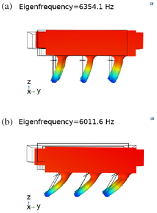
Figure 4. COMSOL simulation of the displacement mode shapes of two designs of micro-bristle-bots corresponding to bending of the legs. (a) Deformation of the bristle-bot with the straight leg design, showing a resonant frequency of 6.3541 kHz. (b) Deformation of the bristle-bot with 30° tilted leg design showing a resonant frequency of 6.0116 kHz.
Download figure:
Standard image High-resolution imageThe small discrepancy between the simulated resonant frequencies of the mode-shapes in figure 4 and the measured frequency of 6.3 kHz (shown in section 3.2) can be explained by non-ideal fabrication and material properties. Furthermore, the leg tips are fixed to the ground in the simulation, whereas in practice, the friction forces applied to the leg tips shift the resonant frequencies of the two designs.
2.3. Fabrication process
The 5 mg micro-bristle-bot is composed of two parts: a polymer base and a small diced PZT plate placed between a top and a bottom metal electrode. It must be noted that the PZT actuator in this work serves as a passive mass and is not used for actuation. A 300 µm thick PZT plate from APC International, Ltd [25] is diced into 2 mm × 1.5 mm rectangles. The polymer base includes the housing for the PZT mass and legs of the micro-bristle-bot. The diameter of the legs is 100 µm, and the overall height of the legs is 500 µm for all designs. Autodesk Inventor was used for creating 3D models of the polymer base.
As shown in figure 5(a), the designed polymer base was fabricated with Ip-S photoresist droplet on indium tin oxide (ITO) coated glass slide using two-photon lithography with Nanoscribe Photonic Professional. The monomer polymerizes around the focal point of the laser where the two-photons meet [26]. Once the Ip-S polymer base has been written, it is developed in a SU-8 developer. Once the polymer base been washed and dried with isopropyl alcohol, it is removed from the ITO glass slide, with gentle nudge from a tweezer placed on the legs. Adhesive is applied onto the diced PZT by using a needle as shown in figure 5(b). Then the polymer base and the diced PZT mass are manually assembled using a plier as shown in figure 5(c). Next the assembly is flipped onto the PZT side and middle section of polymer base is gently pressured with a tweezer to ensure even spread of the adhesive. Finally, the 5 mg micro-bristle-bot is placed on its leg as shown in figure 5(d). A completed micro-bristle-bot is shown in figure 6.
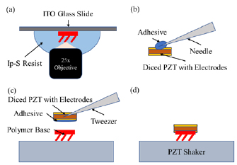
Figure 5. Process flow of micro-bristle-bot. (a) Direct write two-photon polymerization of Ip-S photoresist is used to create polymer base with 25 × objective lens. (b) Adhesive is applied on the diced PZT plates with a needle. (c) The polymer base is placed on its leg on flat surface and the diced PZT is inserted using tweezers. (d) The completed 5 mg micro-bristle-bot is placed on its legs on PZT shaker for testing.
Download figure:
Standard image High-resolution image
Figure 6. Close-up image of the 5 mg micro-bristle-bot, showing the PZT actuator block on top and the polymer legs/base printed with two-photon-lithography.
Download figure:
Standard image High-resolution imageA concern with polymer based flexural elements is the performance degradation due to self-heating from high frequency operations as described in [27]. However, polymerized Ip-S resin used in this work for fabrication of bristle-bots does not show degradation below T = 300 °C as it is a thermoset polymer [24].
2.4. Test setup
A lead zirconate titanate or PZT-4 crystal disc supplied by Stem, Inc [28] is utilized as a piezoelectric shaker. PZT disc is connected to a Krohn-Hite 7602M amplifier which in turn is connected to an Agilent 33220A Function Generator. The disc vibrates in the out-of-plane mode with a  piezoelectric coefficient of 320 × 10−12 m V−1 underneath a glass substrate with marked distances. A dot was painted on top of the micro-bristle-bots as a marker, and a Olympus SZ-12 14MP digital camera is used to capture the motion of the bristle-bot at 30 fps with a 1280 × 720 resolution. DLTdv digitizing tool from [29] is used for analyzing the motion by tracking the painted marker on the micro-bristle-bot.
3. Results and discussion
3.1. X-Y trajectories of micro-bristle-bots
Two different variations of the micro-bristle-bots with different leg angles were placed on the piezoelectric shaker with distance markers. A sinusoidal wave was applied to the piezoelectric shaker with varying frequencies and voltage amplitudes, ranging from 4 kHz to 8 kHz and 5 V to 25 V corresponding to 1.6 nm to 8 nm of vertical displacement. Figure 7 shows four time frames of the locomotion of the two micro-bristle-bots. More trajectories of straight leg and tilted leg designs are shown in figure 8. The trajectories of straight leg design is erratic and random as the robot tends to turn and spin, whereas the trajectories of the bristle-bot with tilted legs are smooth and directional. The resulting variance of distances between each end coordinate of the trajectories shown in figure 8 is 28.58  for straight leg design and 5.21
  for the tilted leg design.
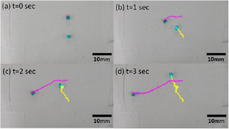
Figure 7. Time frames of the locomotion of two different types of micro-bristle-bots excited at 17.5 V input amplitude or 5.6 nm vertical displacement amplitude and 6.3 kHz input frequency. 30° tilted leg micro-bristle-bot starts at the top, represented by pink path. Straight leg micro-bristle-bot starts at the bottom, represented by yellow path. Both bristle-bots face towards left at t = 0 s. Each frame is incremented in  s steps. (a) t = 0 s, (b) t = 1 s, (c) t = 2 s, and (d) t = 3 s.
Download figure:
Standard image High-resolution image
Figure 8. Visualization of trajectories from three runs taken by micro-bristle-bot during 5 s time period starting at point (0 mm, 0 mm) facing positive x-direction. (a) Straight leg design. (b) 30° tilted leg design. The black arrows indicate the front side of micro-bristle-bot. Note how the paths of tilted leg micro-bristle-bot are directional, compared to the random paths of the straight leg micro-bristle-bots.
Download figure:
Standard image High-resolution image3.2. Study of speed dependency on actuation frequency and amplitude
3D plots of the micro-bristle-bot speed versus input frequency and displacement of the PZT shaker are shown in figures 9(a) and (b) for the straight leg design and 30° tilted leg design, respectively. The speed of micro-bristle-bots depend on the periodic displacement of leg tips, d, as shown in figure 3, which in turn depends on the input voltage, and the input frequency of the oscillations according to equations (1)–(3). As demonstrated in the figure 9, a resonant behaviour is observed around 6.3 kHz corresponding to the bending of the legs, matching the FEA results shown in figure 4. As vertical displacement of piezoelectric shaker increases, the speed shows an increasing trend. Larger displacement amplitudes can result in jumping and flipping of the micro-bristle-bots which is not desired. Therefore, the actuation voltage was kept below 25 V. Although the resulting speed of straight leg design is only slightly lower than that of the tilted leg design, the straight leg design's trajectory is less directional, as each of the six legs can buckle in any arbitrary direction, and thus suffers from erratic movement.

Figure 9. Average speed plots versus excitation frequency and displacement of the piezoelectric shaker for (a) straight-legged micro-bristle-bot, and (b) 30° tilted leg micro-bristle-bot.
Download figure:
Standard image High-resolution image
4. Conclusions
This paper presents the first demonstration of locomotion of 3D-printed micro-bristle-bots. The micro-bristle-bots are fabricated using two-photon lithography to create legs of varied designs and carry a PZT actuator, attached to their base. It is shown that by targeting the resonant frequency of the system, the micro-bristle-bots can be actuated at below 25 V input amplitude and still maintain speed of four times body length per second by taking advantage of the resonant behavior of such systems. Both straight leg design and 30° tilted design show positive correlation of speed with vertical displacement amplitude of shaker. However, the trajectories micro-bristle-bots with tilted legs are more consistant, directional, and smooth, whereas the trajectories of straight-legged micro-bristle-bots are more erratic and random. The resulting variance of distances between each end coordinate of the trajectories are 28.58  for straight leg design and 5.21 mm2 for tilted leg design. This work marks the first steps of a 3D-printed resonant micro-bristle-bot that carries an on-board PZT actuator, achieving directional trajectories by optimized leg design.
Acknowledgments
This work was supported by Georgia Tech Instutute of Electronics and Nanotechnology (IEN) seed grant through MIAMuR (Muscle-Inspired Actuators for Multi-scale Robotics) project. The authors would like to acknowledge Prof S Sponberg's lab for lending the high-speed camera, Dr D Gajula for his insights on the experiment, and Dr A R Mohazab for the helpful discussions and proof-reading the manuscript. The device fabrication was performed at the Georgia Tech Institute for Electronics and Nanotechnology, a member of the National Nanotechnology Coordinated Infrastructure (NNCI), which is supported by the National Science Foundation (Grant ECCS-1542174).