

Abstract
This study presents design and fabrication of a novel magneto-rheological (MR) damper with bifold flow mode gap to improve damping performance. The proposed MR damper is featured by inner flow mode gap connected to the outer flow mode gap through the feedback hole. A mathematical model of the damping force is established for the proposed MR damper and the magnetic circuit has been analyzed with the finite element method, which is used to validate the principle of the proposed MR damper. A conventional MR damper is fabricated with the same dimensions (radius, length) of the piston and is experimentally compared to confirm advantages of the proposed MR damper. The mechanical performance of the proposed MR damper is experimentally investigated and compared with the results by mathematical model and finite element analysis. The research results show that the controllable damping force and equivalent damping of the MR damper with bifold flow mode gap are much larger than those of the conventional MR damper.
Export citation and abstract BibTeX RIS
1. Introduction
Magneto-rheological (MR) fluids, one kind of smart materials, are fluids which mechanical properties can be changed by applying magnetic field. The rheological property of MR fluids can be changed by using low power consumption, and immediate response to external action is possible. Recently, the application of the MR fluid has been quickly developed, which is widely used in the machinery, automobile, aerospace, civil engineering and medical engineering technology.
According to the work mode, MR dampers can be classified into three types; shear mode [1, 2], flow mode [3–5] and squeeze mode [6–9].
Some researchers showed that the mixed mode damper can achieve the damping force better than single mode MR dampers. Yazid et al [10] designed a MR damper with a combination of shear and squeeze modes, simulated the magnetic field by finite element method, and experimentally evaluated the damping characteristics of the MR damper. Mughni et al [11] suggested a new MR cell under combination of flow and shear-flow modes and simulated the magnetic circuit by finite element method, and tested the fabricated cell under quasi-static loading.
MR dampers featuring bypass valve and bifold valve were proposed to improve the controllable damping force. Hu et al [12] designed an energy absorber using a MR bypass valve filled with ferromagnetic beads, and empirically evaluated its performance. Robinson et al [13] estimated effects of porous media selection on the performance of a porous-valve-based MR bypass damper and the identified important media parameters affecting the damper performance by using flow analysis. Bai et al [14] presented the design, fabrication and test of a MR damper utilizing an inner bypass that can simultaneously produce large dynamic range and low field-off stroking load at high piston velocity. McLaughlin et al [15] examined performance of an MR damper with a spiral channel bypass valve. Sohn et al [16] proposed a novel MR damper featuring piston bypass hole and estimated the effectiveness of the mechanical performance by the numerical simulations and experiment.
The controllable damping force of the MR dampers with bypass valves is much larger than that of the traditional MR dampers, but always occupies much larger installation space. Mao et al [17] suggested a configuration of a flow mode bifold MR damper for shock and vibration mitigation at high piston velocity as well as for low velocity.
In general, to obtain larger controllable damping force, diameter and length of the piston have to be increased, leading to larger dimension and installation space of the MR damper. Therefore, some researches focused on larger damping force in limited dimension of the MR damper. One of these ways is to effectively use of applied magnetic field by combining multiple flow channel of MR fluids in MR damper piston. Bai et al [18] designed MR damper with annular-radial duct in the piston, established the mathematical model, and compared the performance with the conventional MR damper by experiment. Phu et al [19] proposed a new type of a MR fluid mount based on two operating modes of MR fluid, experimentally investigated and compared results between the proposed and conventional MR mounts. Imaduddin et al [20] presented a novel design for an MR valve using the meandering flow path which can increase the effective area, formed the meandering flow path by combining multiple annular, radial and orifice flow channels.
The technical originality of this paper is to propose a novel MR damper configuration featured by the bifold flow mode gap in the piston to obtain larger controllable damping force within the limited volume. A mathematical model for the proposed MR damper is established, and the magnetic circuit is analyzed by finite element method, and numerical simulations for the damping force characteristics are carried out while changing several values of current.
The proposed MR damper is designed and fabricated, and the damping performance is experimentally investigated and compared with the analytical simulation result. In addition, the conventional MR damper with the same dimension of the piston of the proposed MR damper is fabricated, as shown in figure 1, and the equivalent damping of the proposed MR damper is compared with that of the conventional MR damper.
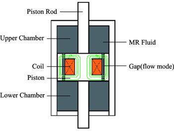
Figure 1. Conventional MR damper.
Download figure:
Standard image High-resolution imageThe effectiveness of the MR damper with the bifold flow mode gap is confirmed by the investigated results.
2. Design of MR damper featured by bifold flow mode
The structure of the proposed MR damper is shown in figure 2, and the main structural dimension parameters are listed in table 1. Figure 2(d) shows the photograph of the exploded components for the proposed MR damper fabricated with the dimensions as listed in table 1. The proposed MR damper consists of the damper housing, outer piston, inner piston with rod, two magnetic cores with feedback holes, an exciting coil wound on bobbin, seal ring and two piston covers, which are shown in figure 2(a). The bobbin, seal ling and piston covers are fabricated from nonmagnetic materials. The proposed MR damper is featured by the bifold flow mode annular gaps (outer and inner). The bolts fixing the piston cover to the magnetic core guarantee the thickness of an annular inner gap.
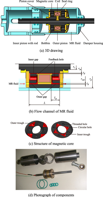
Figure 2. Configuration of the proposed MR damper.
Download figure:
Standard image High-resolution imageTable 1. Main structural dimension of the proposed MR damper.
| Parameter | Symbol | Value |
|---|---|---|
| Radius of outer piston | rp | 22.5 (mm) |
| Length of piston | L | 29 (mm) |
| Radius of inner piston | rin | 8 (mm) |
| Radius of piston rod | rr | 5 (mm) |
| Radius of magnetic core | rout | 18 (mm) |
| Thickness of gap | td | 1 (mm) |
| Length of magnetic core | Lp | 8 (mm) |
| Exciting coil turns | N | 300 (turns) |
The magnetic core has four circular holes, and every circular hole is connected to outer and inner gap by two troughs (outer and inner), respectively. And each feedback hole consists of a circular hole and two troughs (outer and inner), as shown in figure 2(c).
As shown in figures 2(a) and (b), as the piston compresses relatively to damper housing, the MR fluid flows from the left outer gap into the left feedback hole, and the MR fluid flows into the inner gap through the left feedback hole. Then, the MR fluid flows into the right feedback hole through the inner gap, and the MR fluid flows into the right outer gap through the right feedback hole. At last, the MR fluid flows out of the piston through the right outer gap.
The magnetic flux generated by the exciting coil with current starts from the left magnetic core, goes through the left outer gap, along the outer piston, through the right outer gap, along the right magnetic core, through the inner gap, along the inner piston, through the inner gap to complete a closed magnetic circuit. It is assumed that the MR fluid in the feedback hole is not affected by the magnetic field, because most of the magnetic flux makes detour around feedback holes.
As the current applied to the exciting coil increases, the yield stress increases continuously, but before the magnetic flux density in the magnetic circuit is saturated. As a result, it is possible to control the damping force generated by the MR damper with changing the current applied to the exciting coil.
3. Mathematical modeling
As shown in figure 2(b), the operation modes of the MR fluid in the outer and inner gap of the MR damper are the flow modes. The damping force of the MR damper can be expressed as

where ΔPout and ΔPin are the pressure drops through the outer and inner gap, respectively; ΔPlm is the minor loss pressure drop due to the elbows, such as sudden expansions and contractions along the MR fluid flow channels; Ap is the effective area of the piston which can be written as follows:

where rp, rout and rr are the radii of the piston, magnetic core, and piston rod, respectively; td is the thickness of the outer and inner gap.
The pressure drop of the outer gap can be expressed as follows:

where ΔPηo and ΔPτo are the viscous pressure drop and the pressure drop due to the yield stress, and they can be expressed as follows:


where η is the viscosity of the MR fluid without magnetic field; Qout is volumetric flow rate of the MR fluid through the outer gap and Qout = ApVp if Vp is the velocity of the piston; Lp is the effective length of the magnetic core; τyo is yield stress of the MR fluid in the outer gap; cout is coefficient dependent on the volumetric flow rate and yield stress of the MR fluid through outer gap which can be given by [21]
The pressure drop of the inner gap of the piston can be expressed as follows:


where Qin is volumetric flow rate of the MR fluid through the inner gap and Qin = Qout; L is length of the inner gap; τyi is yield stress of the MR fluid in the inner gap; rin is radius of the inner piston.
cin is coefficient dependent on the volumetric flow rate and yield stress of the MR fluid through inner gap and can be given by
The minor loss pressure drop ΔPlm in equation (1) can be given by [18, 22]

where ρ is the mass density of the MR fluid; Vout, Vin, and Vfeedback are the average flow rates of the MR fluid in the inner gap, outer gap, and feedback channel of the core, respectively; Kml is the overall minor loss coefficient [18, 22].
Combining equations (1)–(3), (7) and (11), the damping force of the proposed MR damper can be rewritten as follows:
If E is the energy dissipated in one cycle (i.e., the area inside the force versus the displacement diagram), then the equivalent damping [23] is given by

where ω is the excitation frequency, X is the amplitude of the sinusoidal displacement excitation to the proposed MR damper, and E is given by

where  is the velocity of the piston of the proposed MR damper under the sinusoidal displacement excitation.
The damping coefficient or dynamic range, a widely used metric for damper performance, is the ratio between field-on (Ceq) and field-off (C0) values of equivalent viscous damping.
4. Simulation
The finite element analysis for the proposed MR damper is carried out using ANSYS/Emag software.
As shown in figure 3(a), because the structure of the proposed MR damper is distributed symmetrically, half model of magnetic circuit is used for the finite element analysis.
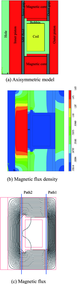
Figure 3. Magnetic characteristics of the proposed MR damper.
Download figure:
Standard image High-resolution imageFigure 3(a) shows the axis-symmetric model of the piston of the proposed MR damper with the structural dimensions as listed in table 1 for FEA. Figures 3(b) and (c) show the corresponding contours of the magnetic flux density and the magnetic flux of the proposed MR damper applied with a current of 1.75 A, respectively. As shown in figure 3(b), when the exciting coil is applied with a current of 1.75 A, the magnetic flux densities in the outer and inner gaps are nearly 0.4 T and 0.8 T, respectively. As shown in figure 3(c), the contours of the magnetic flux of the proposed MR damper are shown as the closed magnetic circuit, which validates the principle of the MR damper with bifold flow mode gap. As shown in figure 4, at the field-on status, i.e., in the maximum current case, the magnetic flux densities along the outer and inner gaps are obtained by using two detecting paths in the outer and inner gaps. The magnetic flux density of the inner gap along the detecting path 2 is larger than that of the outer gap along the detecting path 1, and the magnetic flux densities of the outer gap and inner gap are 0.39 and 0.8 T, respectively.
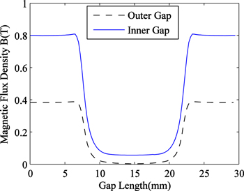
Figure 4. Magnetic flux densities in the gaps under a current of 1.75 A.
Download figure:
Standard image High-resolution imageAs given by equations (1)–(12), the damping force of the proposed MR damper is determined by three factors: the structure dimensions of the proposed MR damper, the yield stress of the MR fluid in gaps, and the excitation velocity. In other words, substituting the magnetic flux density along the MR fluid flow gaps obtained by the finite element analysis into equation (15), the yield stress of the MR fluid can be obtained, the damping force of the proposed MR damper could be calculated by the established mathematical model (equations (1)–(12)).
Similar to the field-on state shown in figure 3(b), by finite element analysis, the magnetic flux densities of the inner and outer gap of the proposed MR damper under the currents of 0.5, 1.0, 1.25 and 1.75 A can also be obtained. The magnetic flux densities along the inner and outer gaps of the proposed MR damper are 0.10 and 0.22 T for the currents of 0.5 A, 0.25 and 0.54 T for the currents of 1.0 A, 0.35 and 0.73 T for the currents of 1.25 A, 0.39 and 0.8 T for the currents of 1.75 A.
In this study, the hydrocarbon-based MR fluid product (MRF-132DG) from Lord Corporation was used, the field-independent plastic viscosity is η = 0.112 Pa s. It is noted that the fluid post-yield viscosity is assumed to be a constant in the Bingham model.
By applying the least-squares curve fitting method to the fluid property specifications [24], the approximate polynomial curve of the yield stress is shown in figure 5 and the corresponding approximate polynomial of τy(B) is given by

Figure 5. The field-dependent yield stress of the MR fluid.
Download figure:
Standard image High-resolution imageFigure 6 shows the simulated damping force characteristics of the proposed MR damper under sinusoidal displacement excitation of frequency of 2 Hz. When the maximum current is I = 1.75 A, and the maximum damping force is 3000 N, and the minimum damping force is −3000 N.
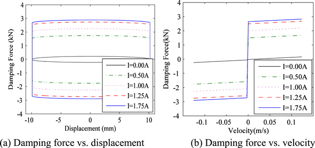
Figure 6. Damping force characteristics.
Download figure:
Standard image High-resolution imageFigure 7 shows the simulated equivalent damping for the MR dampers. As the current input increases, the equivalent damping for the MR dampers increases, and as excitation frequency increases, the equivalent damping for the MR dampers decreases. As shown in figures 7(a) and (b), the equivalent damping for the proposed MR damper is much larger than that of the conventional MR damper in the entire range of frequency. In addition, at no current input, the equivalent damping is nearly constant with frequency, and the equivalent damping of the proposed MR damper is much larger than that of the conventional MR damper due to the extension and complexity of the flow channel.
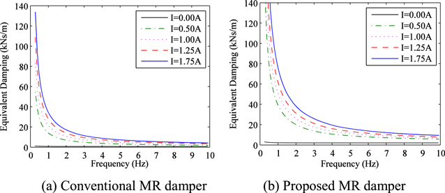
Figure 7. Equivalent damping characteristics.
Download figure:
Standard image High-resolution imageFigure 8 also shows the simulated damping coefficient for the MR dampers with the increase of the excitation frequency. As the current input increases, the damping coefficient for the MR dampers increases, and as excitation frequency increases, the damping coefficient for the MR dampers decreases. As shown in figures 8(a) and (b), the damping coefficient for the proposed MR damper is almost the same with that of the conventional MR damper in the entire range of excitation frequency because the extension of the flow channel results in enhance of the pressure drop due to the yield stress at the field-on state, at the same time, the viscous pressure drop and minor loss pressure drop at the field-off state is also increased. As a result, this suggests that bigger equivalent damping can be obtained by the structure of proposed MR damper under the same damping coefficient and dimension with the conventional MR damper.
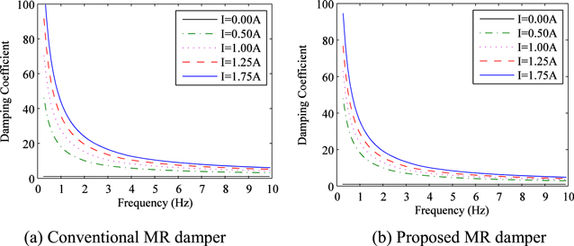
Figure 8. Damping coefficients (Ceq/C0).
Download figure:
Standard image High-resolution image5. Experiment of mechanical performance
The proposed MR damper, as well as a conventional MR damper with a flow mode gap, are tested based on the hydraulic servo testing machine and auxiliary devices, as shown in figure 9.

Figure 9. Experimental setup for measuring damping force of MR damper.
Download figure:
Standard image High-resolution imageFigure 10 shows the measured damping force characteristics of the proposed MR damper under sinusoidal displacement excitations with same current of 1 A, same frequency of 2 Hz and different amplitudes. It is obvious that the damping force increases with the increase of the velocity under the same current, however change of amplitude has a slight influence on the damping force.
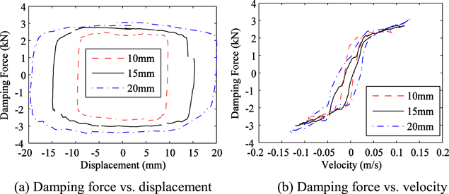
Figure 10. Damping force characteristics (1 A, 2 Hz).
Download figure:
Standard image High-resolution imageAs shown in figure 11, the higher frequency the larger is its damping force under the same current of 1 A and amplitude of 10 mm, increases with the increase of frequency, i.e., the damping force increases with the increase of the piston frequency.
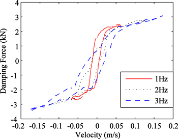
Figure 11. Damping force characteristics (1 A, 10 mm).
Download figure:
Standard image High-resolution imageFigure 12 shows the measured damping force characteristics of the proposed MR damper under sinusoidal displacement excitations with frequency of 2 Hz and amplitude of 10 mm for five current levels: 0.00 A, 0.50 A, 1.00 A, 1.25 A, and 1.75 A. When the maximum current is 1.75 A, the maximum damping force is 3250 N, minimum damping force is −3550 N, and the range between of the maximum and minimum damping force is 6800 N.
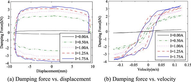
Figure 12. Damping force characteristics (2 Hz, 10 mm).
Download figure:
Standard image High-resolution imageAs shown in figure 12, under the certain displacement excitations with frequencies of 2 Hz, the damping force of the proposed MR damper enhances with the increasing current. As increasing the current from 0.00 to 1.25 A, the damping force is significantly proportional to the increment of the current. Besides, when the current exceeds 1.25 A, as increasing the current increasing, the saturation in the magnetic circuit of the proposed MR damper is more significant and the damping force slightly increases.
The viscous damping force of the proposed MR damper at the field-off status, i.e., no current case, is difficult to model due to complexity of the MR fluid flow channels. However, as shown in figures 6 and 12, the simulated damping forces are in comparative agreement with the measured damping force, verifying the effectiveness of the constructed damping force model. With increment of the current, the measured and simulated damping forces increase, and the damping force simulated by the theoretical model could still follow the measured damping force. The experimental results are slightly larger than the simulated ones, as shown in figures 6 and 12, because the theoretical model cannot reflect the minor loss pressure drop due to the elbows, such as sudden expansions and contractions along the MR fluid flow channels.
Furthermore, the difference between the curve simulated by Bingham model and the experimental curve was caused by the disadvantage of the Bingham model. Bingham model fairly predicts only the magnitude of the damping force at a certain piston velocity, but it cannot capture the nonlinear hysteresis behavior. However, the Bingham model is widely used to predict damping force at design stage of MR damper, because of its simple model, obvious meaning, and easiness of understanding and analysis.
Figure 13 shows the damping force ranges of the proposed MR damper and the conventional MR damper for currents of 0.00 and 1.75 A in experiment. As shown in figure 13, the damping force range of the proposed MR damper is much larger than that of the conventional MR damper, in case of the same currents and excitation velocities for both of those MR dampers. When velocity of the piston is 0.125 m s−1, damping forces of the proposed MR damper for currents of 0.00 A and 1.75 A is 240 N and 3250 N, and damping forces of the conventional MR damper for currents of 0.00 A and 1.75 A is 160 N and 1640 N, respectively. We can see that the damping force range of the proposed MR damper is more than twice in comparison with that of the conventional MR damper.
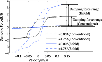
Figure 13. Damping force ranges.
Download figure:
Standard image High-resolution imageFigures 14(a) and (b) show the equivalent damping of the proposed MR damper and conventional MR damper under sinusoidal displacement excitations with amplitude of 10 mm for current range of 0.00–1.75 A using equations (13) and (14), respectively. As shown in figure 14, under the same excitations of the current and sinusoidal displacement, the equivalent damping of the proposed MR damper is much larger than that of the conventional MR damper.

Figure 14. Equivalent damping.
Download figure:
Standard image High-resolution image
In addition, the equivalent damping of the proposed MR damper saturates significantly when the current exceeds 1.25 A, while the equivalent damping of the conventional MR damper saturates when the current exceeds 1.00 A.
It can be concluded that the magnetic circuit configuration of the proposed MR damper with the bifold flow mode gap could be more efficiently in using magnetic flux density.
As shown in figures 14(a) and (b), the equivalent damping of the MR dampers decreases with increment of the excitation velocity, and the equivalent damping of the proposed MR damper is significantly larger than that of the conventional MR damper. In addition, when excitation velocity reaches 0.125 m s−1, the equivalent damping for the proposed MR damper reaches over twice of that for the conventional MR damper.
6. Conclusion
This paper proposed a novel MR damper featuring bifold flow mode to improve damping performance. Based on the principle of the novel MR damper, the proposed MR damper was designed and fabricated. In order to be compared with the proposed MR damper, the conventional MR damper was fabricated. The mathematical model of the proposed MR damper was derived to predict damping performance. The principle of the proposed MR damper was validated and the electromagnetically analysis for the magnetic circuit was performed by FEA using ANSYS/Emag software. Under the same excitations of current and sinusoidal displacement, the controllable damping force and equivalent damping of the proposed MR damper have been experimentally compared with those of the conventional MR damper. Based on the experimental result, the proposed MR damper could provide a large controllable damping force as high as 3150 N and equivalent damping of more than twice of the conventional MR damper under excitation velocity of 0.125 m s−1. Therefore, it can be concluded that the magnetic circuit and damping performance of the proposed MR damper have advantages over the conventional MR damper with the same dimensions.
Acknowledgments
This research was funded by the National Natural Science Foundation of China (Grant No.11372803).