

Abstract
In recent years, various types of magnetorheological brakes (MRBs) have been proposed and optimized by different optimization algorithms that are integrated in commercial software such as ANSYS and Comsol Multiphysics. However, many of these optimization algorithms often possess some noteworthy shortcomings such as the trap of solutions at local extremes, or the limited number of design variables or the difficulty of dealing with discrete design variables. Thus, to overcome these limitations and develop an efficient computation tool for optimal design of the MRBs, an optimization procedure that combines differential evolution (DE), a gradient-free global optimization method with finite element analysis (FEA) is proposed in this paper. The proposed approach is then applied to the optimal design of MRBs with different configurations including conventional MRBs and MRBs with coils placed on the side housings. Moreover, to approach a real-life design, some necessary design variables of MRBs are considered as discrete variables in the optimization process. The obtained optimal design results are compared with those of available optimal designs in the literature. The results reveal that the proposed method outperforms some traditional approaches.
Export citation and abstract BibTeX RIS
1. Introduction
Magnetorhelogical fluid (MRF), invented by Rabinow in 1948 [1], is a kind of smart material that includes suspensions of micro-sized or nano-sized particles, which can be magnetically distributed in a carrier such as silicon oil. If a magnetic field is absent, the MRF is considered to be like a Newtonian fluid. However, when a magnetic field is applied, magnetizable particles in the MRF form chains parallel to the magnetic flux, which changes the rheological properties of the fluid. Thanks to fast, strong and reversible changes in the rheological properties, MRFs can be applied in various engineering fields that require an electromechanical interface such as brakes, clutches, valves and dampers [2, 3]. In recent years, there has been much research on the design and development of MRF-based devices, especially MRF brakes (MRBs) with different types such as disc-type [4–11], drum-type [12, 13] and hybrid-type (a combination of disc-type and drum-type) with a T-shaped rotor [14]. An approximated analytical method is also developed for optimal design of the single-disc type MRB based on the linear assumption of the magnetic property of the brake components and a required induction in the MR fluid gap [15].
In the design of MRBs, many performance parameters should be taken into account, such as mass or cost, braking torque, friction torque (off-state torque), compactness (torque per volume ratio), response time, power consumption, heating, etc. There are often trade-off benefits among these performance parameters, for example, to have an MRB with smaller mass or lower cost. The braking torque of the MRB becomes smaller, whereas an increase in braking torque generally results in an increase in off-state torque and heating of the MRBs. An increase in the number of coil turns can improve magnetic density across the MRF ducts by which braking torque can be increased, but results in higher power consumption and longer time response. Therefore, an optimal design of MRB is very significant in the development and application of MRBs. It is hard to take all the performance parameters into account. In practice, several of the above performance parameters are considered in the optimal design of MRBs, depending on practical applications and available resources. Considerable research on the optimal design of MRBs has been performed considering different performance parameters and using different algorithms. Park et al [5] designed a disk-type MRB with two disks, which is controlled by a sliding mode controller. In this paper, a design optimization procedure uses simulated annealing combined with finite element simulations, where the objective function is a linear combination of braking torque and mass. Later, Park et al [6] performed multidisciplinary design optimization for MRBs by three different optimization algorithms: sub-problem approximation, first order and simulated annealing (SA). It was shown that the SA yields the best result, albeit at a computational cost. By maximization of braking torque using the built-in finite element method (FEM)-approximation sequential nonlinear programming (SNLP) optimizer in Ansys–Maxwell, Yaojung Shiao et al [9] showed that their proposed multi-pole MRB can provide large braking torque, while maintaining a compact and solid design with a low input current. Carlos et al [11] developed a multilayered wide-ranged torque MR brake with four fluid MR gaps. In this study, an optimization algorithm using both an SA and sequential quadratic programming algorithm (SQP) is employed. The SA looks for a geometrical solution and guarantees a minimal torque of 3.2 Nm. Subsequently, the SQP maximizes the torque density using this equation as a cost function. Nguyen et al [14] performed optimization of their proposed hybrid-type MRB with a T-shaped rotor, in which the mass is minimized while braking torque is constrained to be greater than a required value using the first-order method. Subsequently, Nguyen et al [16] focused on the optimal design of different types of MRBs considering available space and braking torque. From the results, a suggestion on choosing from the MRB types was also proposed. In the above optimal design of the MRB, the brake housing is rectangular. Recently, Nguyen et al [17] investigated the optimal shape of the brake housing. In this study, the rectangular, the polygonal and the spline-shaped envelope are considered, and the mass is chosen as the objective function, while the braking torque is set as a state variable. The results showed that the mass of the MRBs can be significantly reduced when the polygonal or spline-shaped envelope is used. More recently, Nguyen et al [18] proposed and evaluated a new configuration of disk-type MRB with the coils placed directly on each side of the housings (In this research, this is referred to as side-coil MRB). Simulation results showed that the proposed configuration could eliminate or minimize some disadvantages of the traditional MRB and its mass was significantly smaller than the conventional ones. From the above, it can be seen that the optimal design problem widely used in the literature is to minimize the mass of MRB while the maximum braking torque is constrained to be greater than a required value. This is also the optimization problem used in this study.
It is noteworthy that the optimal design of MRBs is a complex nonlinear optimization problem (due to nonlinearity of magnetic properties of materials, braking torque and mass) characterized by high computation cost and local optimal results. Therefore, our research motivation is initialized by the two shortcomings below from previous research about the optimal design of MRBs:
- Huge time taken to find out the global optimal results of MRBs when the traditional global optimization methods (annealing search, genetic algorithm, etc) are used
- All continuous design variables and local optimal results obtained from gradient-based optimization methods such as first order in ANSYS software.
In order to overcome two above-mentioned shortcomings, the improved differential evolution (DE) proposed by Ho-Huu et al [19] is used in this study. The reason is that the DE is a gradient-free global optimization, whose robustness and reliability in obtaining global optimal results is verified in previous literature [20–25]. In addition, original DE has been improved to improve computational cost and convergent rate [19]. It is also noted that the improved DE method can deal with discrete design variables.
The remainder of the paper is organized as follows. Section 2 provides a brief of the original DE. Section 3 presents two improvements of the DE. The formulation of the optimal design problem and the proposed procedure are presented in section 4. Results and discussion are presented in section 5. Finally, some conclusions are drawn in section 6.
2. DE algorithm
The DE algorithm, first proposed by Storn and Price (1997) [20], is a popular evolutionary algorithm and widely used to solve optimization problems in various engineering disciplines [21–25]. The mathematical structure of the DE is quite simple and consists of four main phases as follows:
2.1. Initialization
First, an initial population, contains NP individuals, is created by randomly sampling from the search space. Each individual is a vector containing D design variables  and is created by
where  and
and  are the lower and upper bounds of
  respectively;
 ![${\rm{rand}}\,[\mathrm{0,1}]$](https://content.cld.iop.org/journals/0964-1726/25/12/125020/revision1/smsaa39ccieqn5.gif) is a uniformly distributed random number in [0, 1]; NP is the size of population; D is the number of design variables.
is a uniformly distributed random number in [0, 1]; NP is the size of population; D is the number of design variables.
2.2. Mutation
Second, each individual in the population called the target vector xi is used to generate a mutant vector vi by means of mutation operations. Several popular mutation operations are usually used in the DE as follows


where integers  are randomly chosen from
  such that
  the mutation factor F is randomly selected within [0, 1]; and
  is the best individual in the current population.
After mutation, the jth components  of mutant vector
  are reflected back to the allowable region if their boundary constraints are violated. This procedure is carried out by

2.3. Crossover
Third, to increase the diversity of the population, each target vector  will create a trial vector
  by means of replacing some elements of the mutant vector
  by some elements of the target vector
  This is implemented as follows
where 
 is an integer selected from 1 to D; CR is the crossover control parameter
 ![$\in \,[\mathrm{0,1}]$](https://content.cld.iop.org/journals/0964-1726/25/12/125020/revision1/smsaa39ccieqn18.gif) .
.
2.4. Selection
Finally, based on the value of the objective function, the trial vector  is compared to the target vector
  The better one with the lower objective function value will be selected for the next generation

If the stopping criteria are met after finishing the selection phase, the searching process will stop and optimal results will be obtained. Otherwise, the algorithm will be repeated from step 2 until the stopping criteria are satisfied.
3. Improvements to the DE algorithm
In the DE, the parameters such as mutant factor F and crossover control parameter CR and trial vector generation strategies have a significant influence on its performance [26]. Commonly, to obtain the most optimized parameters and the most reasonable vector generation strategy for a particular problem, a trial-and-error procedure is used. This may lead to a huge amount of the computational cost. In addition, a rigorous selection mechanism in the selection phase may make the DE converge slowly. Thus, to overcome these restrictions, the paper introduces two improvements proposed by Ho-Huu et al [19]. The first improvement is done in the mutation phase and the second is in the selection phase to enhance the search capability as well as the convergence speed of the DE algorithm. Their details are presented in the next subsections.
3.1. Improvement to the mutation phase
In population-based search methods, the balance between global exploration and local exploitation significantly influences their success [27]. In the DE, the mutation scheme plays a crucial role in its searching ability and convergence rate. There are at least five mutation operators proposed for the DE with different purposes such as 'rand/1', 'rand/2', 'best/1', 'best/2', 'current-to-best/1'. For instance, with the mutation operator 'rand/1', the DE is good at global search, but bad at local search and hence leads to a slow convergence to the global optimal solution [28]. In contrast, with the mutation operator 'current-to-best/1', the DE is good at local search, but bad at global search and easy to be trapped at the local optimal solutions [29]. Thus, to balance the global and local search ability and increase the convergence speed of the DE, a novel adaptive mutation scheme based on the absolute deviation of the objective function between the best individual and the whole population in the previous generation is proposed. This scheme uses two mutation operators. The first is 'rand/1' which aims to ensure diversity of the population and prohibits the population from getting stuck in a local optimum, and the other is 'current-to-best/1' which aims to accelerate the convergence speed of the population by means of guiding the population toward the best individual. These two mutation operators will be adaptively chosen based on a delta value, which is the absolute deviation of the objective function between the best individual and the entire population in the previous generation. The modified mutation scheme is described as follows
where F is a mutation factor, which is randomly created in [0.4, 0.85]; threshold is a criterion value, which is set by the user (e.g. threshold = 10−3).
It should be noted that the value of delta will reduce gradually during the searching process. In the first generation, the delta is often bigger than the threshold. This leads to the mutation operator 'rand/1' which will be used to search, and helps assure the global search ability of the DE. However, after the global search process, the diversity of the population is gradually stable and the delta becomes smaller than the threshold. The deviation of the objective function between the best individual and the entire population becomes small, and then the mutation operator 'current-to-best/1' will be utilized for the searching process. This helps enhance the local search ability and the convergence rate of the DE. Moreover, the mutation factor F is randomly created in the interval [0.4, 1.0] instead of being fixed as in the original DE. This helps increase the variety of searching directions for both cases of the delta (delta > threshold and delta ≤ threshold).
3.2. Improvement in the selection phase
From the selection phase in section 2.4, it can be seen that each trial vector ui created after the crossover phase will be compared with the target vector xi to choose the best individual for the next generation. This technique may ignore some useful information of unselected individuals. Although an individual is not good compared to its target individual in the pair, it can be still be better than other individuals in the whole population. Hence, to hold good information for the next generation, in this paper, the elitist selection technique introduced in [30] will be utilized in order to replace the basic selection in the DE. This procedure is described as follows: first, the children population C containing trial vectors is mixed with the parent population P including target vectors for creating a combined population Q. Next, NP best individuals in Q are selected to construct the new population for the next generation. In this way, the best individual of the whole population is always stored for the next generation and hence the algorithm will obtain a better convergence rate.
4. Optimal design of MRBs using the improved DE
4.1. The optimal design problem of MRBs
As mentioned in section 1, the objectives of MRB optimal design are diverse. In this paper, the aim of our research is to reduce the mass of MRBs in order to decrease the MRB size and cost. Hence, the objective of the optimization is to find the lightest structure of the MRBs that can provide the required braking torque. The optimal design problem can be expressed as [18]


where mb is the total mass of MRB, Vd, Vh, Vs, VMR, Vbob and Vc are respectively the geometric volume of the disc, the housing, the shaft, the MRF, the bobbin and the coil of the brake; ρd, ρh, ρs, ρMR, ρbob and ρc are density of the discs, the housing, the shaft, the MRF, the bobbin and the coil material, respectively; xiL, xiU are the lower and upper geometric dimension limits of each design variable xi ; n is the number of design variables; [T0] is the required braking torque of the MRB; Tb is the induced braking torque.
4.2. Proposed optimization method
Two optimization methods: the original DE and improved DE are applied to the above problem via the integrated procedure. The flowchart of the ANSYS-MATLAB integrated optimization using the DE and improved DE algorithm is shown in figure 1. First, modeling data are generated in MATLAB by an optimization method. These data are then used to create the CAD model in ANSYS. In order to solve the magnetic circuits of the MRBs, a 2D-axisymmetric couple element (PLANE13) is utilized to solve the magnetic circuits of the MRBs. It is noted that the rheological parameters of the MRF such as yield stress and post yield stress are dependent on the magnetic density across the MRF ducts and calculated by [31]

where Y stands for a rheological parameter of the MRF. The value of Y tends from the zero-applied field value Y0 to the saturation value Y∞. αSY is the saturation moment index of the Y parameter. B is the applied magnetic density.

Figure 1. Flowchart of the DE-based optimization for MRBs.
Download figure:
Standard image High-resolution imageIn this study, it is assumed that the shape of the MRB coils is rectangular and its geometric dimensions are calculated as follows

where wc and hc are correspondingly the width and the height of coil; nwc and nhc are respectively the number of wire layers along the width and the height of the coil, which are the positive discrete integer variables; dc is the diameter of wire. It is observed from equation (14) that wc and hc are discrete variables. This is a benefit of the proposed method compared to gradient optimization methods [18].
In the finite element analysis (FEA) implemented to investigate the MRB characteristics, a current density is applied to the coils of the MRBs. Assuming that the coil is fully wound and the insulation layer on the wire is thin, the applied electric current can be considered uniformly distributed over the whole cross-section of the winding with a density j,
where N and I are correspondingly the number of turns in the winding and the applied current.
After obtaining the magnetic density across the MRF ducts, the braking torque and off-state force is estimated by [18]. The value of braking torque is put into MATLAB in order to check the constraint. The mass of the MRBs (the objective function of the MRB optimal design problem) is calculated by equation (10) and the convergence criteria are evaluated. If the convergence criteria are satisfied, the program stops and the best design is output to the MATLAB screen.
5. Result and discussion
In this section, some problems investigated in the study [18] are considered as a reference to evaluate the proposed approach. These cases involve the rectangular and polygonal-shaped conventional MRBs, and the rectangular and polygonal-shaped side-coil MRBs. The shaft rotation speed of the brake is set at 30 RPM. The magnetic components such as the housing and the disc are made of commercial silicon steel, while the brake shaft is made of stainless steel (inox). The coil wires sized as 21-gauge (diameter = 0.511 mm) have a maximum working current around 3 A. However, in this research, for safety reasons a current of 2.5 A is applied to the coil. The MRF used in this study is MRF132-DG, which is made by Lord Corporation. The magnetic properties of the MRB components are summarized in table 1 and figure 2, while the mass density of the MRB components are presented in table 2. The rheological parameters of the MRF132-DG achieved from experimental results using a curve-fitting method are given as: 


 Similar to [18], the gap size of the MRB ducts is not set as a design variable in this optimization and it is fixed at 1 mm, the bobbin thickness is fixed at 0.4 mm and the shaft radius is set at 6 mm considering the strength of the shaft at a required braking torque up to 10 Nm.
Table 1. Magnetic properties of the MRB components.
| Material | Relative permeability | Saturation flux density |
|---|---|---|
| Silicon steel | B-H curve (figure 2(a)) | 1.55 Tesla |
| Copper | 1 | |
| MRF132-DG | B-H curve (figure 2(b)) | 1.65 Tesla |
| Stainless steel | 1 | x |

Figure 2. Magnetic properties of silicon steel and MRF.
Download figure:
Standard image High-resolution imageTable 2. Mass density of the MRB components.
| MRB component | Material | Mass density (kg m−3) |
|---|---|---|
| Disk and housing | Silicon steel | 7800 |
| MRF | MRF132-DG | 2950 |
| Coil | Copper | 8900 |
| Shaft | Stainless steel | 7900 |
Both the original DE and the improved DE are used to find out the geometric dimensions of the MRBs. A comparison of the design variables, the value of the objective function and computation cost for each case is performed. However, for the sake of brevity, only a few investigations are presented for the improved DE, such as the convergence history of the design variables, braking torque and the magnetic distribution of each MRB. After conducting some investigations, significant parameters relating to the operation of the improved DE are recommended. The population size NP and the threshold are set at 20 and 10−4 respectively. The values of the mutant factor F and the crossover control parameter CR are respectively set within the range [0.4, 1.0] and [0.7, 1.0] for all cases. In addition, the maximum number of generations is set at 1000 and the convergence rate is set at 5 × 10⁻⁴ to ensure that the global optimal result is achieved for the value of the objective function. In the original DE, the values of F and CR are set at 0.8 and 0.9, respectively; and the other parameters are set at the same values as those of the improved DE.
5.1. Conventional MRB
The conventional MRB surveyed in this study includes two types: the MRB with a rectangular-shaped envelope and the MRB with a 7-segment polygonal envelope (in this paper, it is referred to as polygonal-shaped conventional MRB). First, the conventional MRB with a rectangular-shaped envelope, as shown in figure 3, is considered. In this case, significant geometric dimensions of the MRB such as the coil height hc, the coil width wc, the disk thickness td, the inner radius of the disk R1, the outer radius of the disk Rd, the outer radius of the brake R and the housing thickness th are considered as design variables.

Figure 3. Conventional MRB with a rectangular-shaped envelope (Nguyen et al [18]).
Download figure:
Standard image High-resolution imageThe optimum results obtained by this study and those obtained from the ANSYS optimization tool using first-order algorithm [18] are shown in table 3. From the results, it is observed that the DE-based methods and the first-order ANSYS optimization tool offer a solution very close to each other. However, the number of wire layers along the height and the width of the coil obtained from the ANSYS optimization tool are, respectively, 6.82 and 11.2, which are not integers. This is one of the inherent disadvantages of the ANSYS optimization tool. In order to solve this problem, a further optimal solution of the MRB is performed in which the number of wire layers along the height and width of the coil is predetermined based on the previous optimal solution. The optimal solution, in which the number of wire layers along the height and width of the coil is kept constant, respectively, at 7 and 11, shown in brackets in the 'first order' column in table 3. It is noteworthy that the number of wire layers along the height and width of the coil should be chosen such that the number of coil turns is as close as that in the previous optimal solution (In this case, the number of coil turns is 77 which is almost equal to that in the previous optimal solution, 76.38). The results showed that the optimal solution obtained by the ANSYS optimization tool is almost coincident with that obtained from the DE and improved DE methods. Considering the optimal solution from the DE and improved DE method, it is found that the improved DE requires fewer number of generations than the original DE (97 generations for the improved DE, 235 generations for the original DE). Therefore, the computation cost of the improved DE is also reduced significantly (1.159 h for the improved DE, 2.807 for the original DE). It is also noted that the first-order method in the ANSYS optimization tool required 30 iterations in this case to achieve the convergence criteria and in each iteration 25 generations are required for the direction search of the design variables. Therefore, a total of 750 generations has been used in this case. The convergence history of the design variables, and the mass and braking torque are shown in figures 4(a)–(c). It can be seen that after approximately 64 generations of optimization progress of the improved DE, the values of the design variables, and the mass and braking torque become stable. The magnetic distribution of the MRB at the optimum in the case of the improved DE is shown in figure 4(d). It can be seen that the magnetic density is not uniformly distributed in the housing of the MRB. This is because the envelope of the shaft is rectangular, and then the magnetic density reaches maximum value at both sides and at the outer cylinder of the coil. As shown in the figure, the magnetic density at this position almost reaches magnetic saturation of the housing material.
Table 3. Optimal design comparison for the rectangular-shaped conventional MRB.
| Optimal design results | |||
|---|---|---|---|
| Design variables (mm) | First order [18] | DE | Improved DE |
| nwc(layers) | 11.2 (11) | 11 | 11 |
| nhc(layers) | 6.82 (7) | 7 | 7 |
| R1 | 31.5 (31.9) | 29.99 | 29.92 |
| Rd | 52.1 (52) | 51.60 | 51.70 |
| td | 4 (4) | 4 | 4 |
| R | 61 (61.1) | 60.93 | 61.02 |
| th | 4.3 (4.4) | 4.48 | 4.46 |
| Mass of MRB (kg) | |||
| Off-state torque | 1.29 (1.295) | 1.291 | 1.291 |
| (Nm) | 0.14 (0.137) | 0.139 | 0.137 |
| Number of coils | 76.5 (77) | 77 | 77 |
| Turns | 30 [750] | 235 | 97 |
| Iteration/Generation | 2.807 | 1.159 | |
| Elapsed time (h) | |||
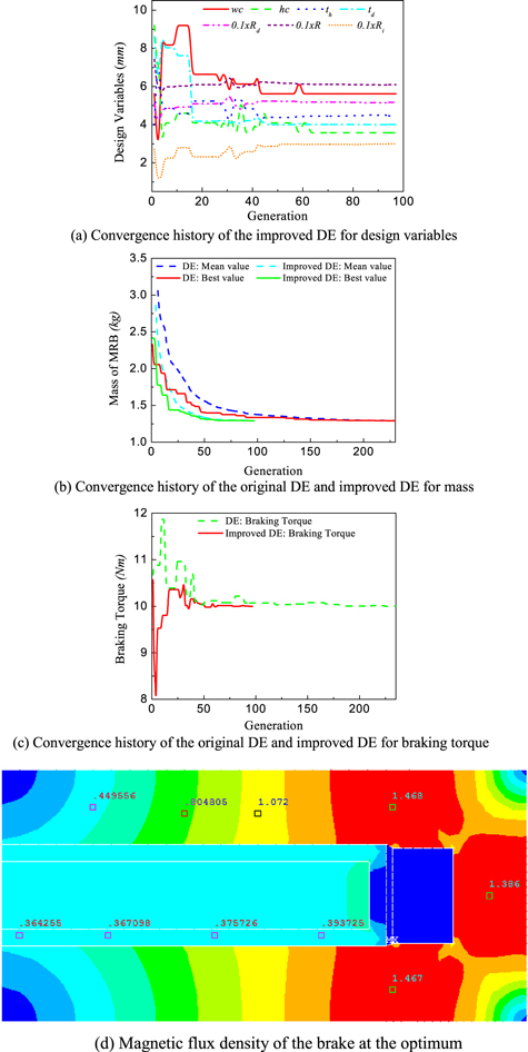
Figure 4. Optimization solution of the rectangular-shaped conventional MRB.
Download figure:
Standard image High-resolution imageSecond, the polygonal-shaped conventional MRB is taken into account. The geometry of the polygonal-shaped conventional MRB is shown in figure 5. In this case, besides the above-mentioned design variables (the coil height hc, the coil width wc, the disk thickness td, the inner radius of the disk R1, the outer radius of the disk Rd, the outer radius of the MRB R and the housing thickness th), the geometric parameters of the control point Pi (Ri, thi) are also set as design variables. Both the original DE and improved DE are applied to determine the optimal design of this MRB. Figure 6 shows the optimal solution of the polygonal-shaped conventional MRB, the result of which is summarized in table 4. From the results, it can be seen that the improved DE can provide a better solution than the original DE, in which the minimum mass is 1.027 and 1.023 kg, respectively. The number of wire layers along the width in the case of the original is 13, while in the case of the improved DE it is 12. This results in the number of coil turns being 91 and 84, respectively. Recognizably, the minimum mass of the polygonal-shaped conventional MRB gained by the DE-based methods is smaller than that obtained from the ANSYS optimization tool, which is 1.27 kg. However, similar to the rectangular envelope MRB, the number of wire layers along the height and the width of the coil obtained from the ANSYS optimization tool is not an integer, respectively 7.5 and 11.92. In addition, the inner radius of the disk (R1) obtained from the ANASYS optimization tool is 15.4 mm, which is much smaller than that obtained from the DE-based methods (around 29.5 mm). The main reason is that the design variable R1 is trapped in a local extremum near its initial value (10 mm). Therefore, a further optimal solution of the MRB is performed in which the number of wire layers along the height and the width of the coil are fixed at 7 and 12, respectively, based on the previous optimal solution and the initial value of R1 is set at 25 mm. The results are shown in brackets in the 'first order' column in table 4. It can be seen that the results are now very close to those obtained from the DE-based methods, especially the optimal value of R1, which is no longer trapped in the local extremum. On the other hand, it can be emphasized that the improved DE reaches the optimal result after 292 generations in 4.339 h, while to gain the optimal result, the original DE needs a greater computation cost with 795 generations in 12.035 h. The geometric parameters of the optimal result are presented in table 4 with the constraint being greater than 10 Nm. It can be seen that the two DEs provide different geometric configurations, but they have almost the same values of the objective function. This discrepancy usually occurs when the number of design variables is numerous. In this case, the problem of MRB optimization becomes very complex. Therefore, the objective function can contain some extrema that have the same value as the global optimal result. The convergence history of design variables, mass and braking torque of this type of MRB are performed in figures 6(a)–(c). It can be realized that after approximately 260 generations of the optimization process of the improved DE, the values of the design variables including mass and braking torque move to the steady state. The magnetic distribution of a 7-control point envelope MRB at the optimum in the case of the improved DE is shown in figure 6(d). It can be observed that the magnetic density is almost uniformly distributed in the housing of the MRB from control point P2. From control point P1 to P2, the magnetic density is much smaller, because the minimum housing thickness is constrained to be greater than 2 mm.
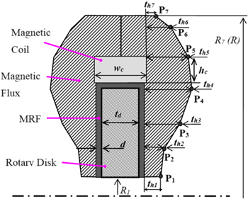
Figure 5. Geometry of the polygonal-shaped conventional MRB (Nguyen et al [18]).
Download figure:
Standard image High-resolution image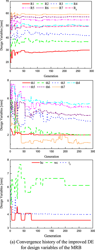
Download figure:
Standard image High-resolution image
Figure 6. Optimization solution of the polygonal-shaped conventional MRB.
Download figure:
Standard image High-resolution imageTable 4. Optimal design comparison for the polygonal-shaped conventional MRB.
| Optimal design results | |||
|---|---|---|---|
| Design variables (mm) | First order [18] | DE | Improved DE |
| nwc(layers) | 11.92 (12) | 13 | 12 |
| nhc(layers) | 7.5 (7) | 7 | 7 |
| Rd | 50.56 (49.79) | 49.32 | 49.32 |
| td | 4 | 4 | 4 |
| R1 | 15.4 (31.78) | 29.36 | 29.97 |
| th1 | 3.6 (2) | 2 | 2 |
| R2 | 23.82 (37.2) | 34.67 | 36.83 |
| th2 | 3.1 (2) | 2.01 | 2.03 |
| R3 | 32.9 (43.15) | 40.52 | 41.83 |
| th3 | 3.08 (3.25) | 2.91 | 3.52 |
| R4 | 42.3 (46.62) | 49.83 | 49.77 |
| th4 | 4.46 (4.81) | 5.61 | 5.45 |
| R5 | 48.2 (56.33) | 54.80 | 54.69 |
| th5 | 5.61 (5.1) | 5.28 | 5.06 |
| R6 | 55.1 (58.1) | 57.03 | 57.16 |
| th6 | 6.05 (4.3) | 4.23 | 4.17 |
| R(R7) | 61.2 (59.48) | 59.06 | 59.19 |
| th7 | 2.85 (2.6) | 1.78 | 1.15 |
| Mass of MRB (kg) | 1.27 (1.08) | 1.027 | 1.023 |
| Off-state torque (Nm) | 0.138 (0.123) | 0.119 | 0.122 |
| Number of coil turns | 84.2 (89.6) | 91 | 84 |
| Iteration/Generation | 35 [945] | 795 | 292 |
| Elapsed time (h) | 12.035 | 4.339 | |
5.2. Side-coil MRB
Similar to the conventional MRBs, the side-coil MRBs considered in this study include the rectangular-shaped MRB and 7-segment polygonal MRB. First, the rectangular-shaped side-coil MRB is considered. In this case, significant geometric dimensions such as the coil height hc, the coil width wc, the disk thickness td, the inner radius of the disk R1, the outer radius of the disk Rd, the outer radius of the MRB R, the housing thickness th and the inner radius of the coils Rc are set as design variables. Figure 7 shows the geometry of the MRB with the rectangular-shaped envelope. Two DE-based algorithms are applied to determine the optimal configuration of this MRB. The optimal results are shown in table 5. The optimal results obtained from the ANSYS optimization tool are also presented in the table. The results show that the minimum mass, the off-state torque and the number of coil turns obtained from the ANSYS optimization tool are respectively 1.24 kg, 0.278 Nm and 68 turns, while the original DE and improved DE reveal, respectively, that the minimum mass for both is 1.129 kg, the off-state torques are 0.291 and 0.297 Nm and the number of coil turns for each coil is 60. It can be seen that the two DEs offer a better solution than the first-order method in ANSYS. In addition, the number of wire layers along the height and the width of the coil obtained from the ANSYS optimization tool is not an integer, respectively 3.16 and 18.75 (the number of coil turns is 59.25). Therefore, a further optimal solution of the MRB is performed in which the number of wire layers along the height and the width of the coil is fixed at 3 and 20, respectively, based on the previous optimal solution (the number of coil turns is 60). The results are shown in brackets in the 'first order' column in table 5. It is also observed that the improved DE outperforms the original DE in computation cost (107 generations in 1.382 h for the improved DE, 309 generations in 3.991 h for the original DE). The convergence history of the design variables, mass and braking torque of this MRB are shown in figures 8(a)–(c). It can be observed that after approximately 68 generations of the optimization process of the improved DE, the values of the design variables, mass and braking torque have become stable. The magnetic distribution of the rectangular-shaped side-coil MRB at the optimum is displayed in figure 8(d). Similar to the rectangular-shaped conventional MRB, it can be seen that the magnetic density is not uniformly distributed in the housing of the MRB. At both sides of the coil, the magnetic density almost reaches magnetic saturation of the housing material.
Figure 7. Rectangular-shaped envelope side-coil MRB (Nguyen et al [18]).
Download figure:
Standard image High-resolution imageTable 5. Optimal design comparison for the rectangular-shaped side-coil MRB.
| Optimal design results | |||
|---|---|---|---|
| Design variables (mm) | First order [18] | DE | Improved DE |
| nwc(layers) | 3.16 (3) | 3 | 3 |
| nhc(layers) | 18.75 (20) | 20 | 20 |
| R1 | 17.4 (26) | 29.93 | 29.93 |
| Rd | 54.7 (56.24) | 57.22 | 57.29 |
| td | 5.57 (4.92) | 4.57 | 4.57 |
| R | 57.7 (59.24) | 60.22 | 60.31 |
| th | 4.35 (3.95) | 3.83 | 3.82 |
| Rc | 41 (42.1) | 43.27 | 43.34 |
| Mass of MRB (kg) | 1.24 (1.2) | 1.129 | 1.129 |
| Off-state torque (Nm) | 0.278 (0.29) | 0.291 | 0.297 |
| Number of coil turns | 59.3 (60) | 60 | 60 |
| Iteration/Generation | 32 [800] | 309 | 107 |
| Elapsed time (h) | 3.991 | 1.382 | |
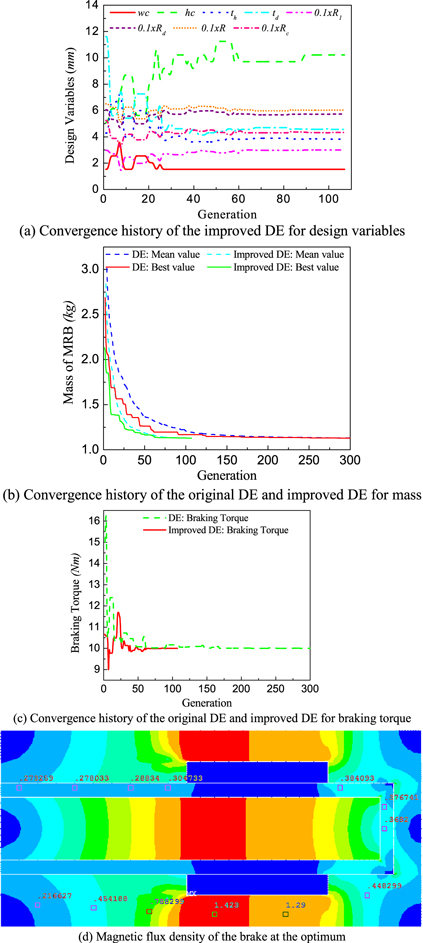
Figure 8. Optimization solution of the rectangular-shaped side-coil MRB.
Download figure:
Standard image High-resolution imageSecond, the 7-control point polygonal envelope side-coil MRB is considered. Figure 9 shows the geometry of the MRB with the 7-control point polygonal envelope. In this figure, the control points of the MRB envelope are defined by their radius Ri and corresponding thickness thi. Besides the previously considered design variables such as the coil height hc, the coil width wc, the disk thickness td, the inner radius of the disk R1, the outer radius of the disk Rd, the outer radius of the MRB R, the housing thickness th and the inner radius of the coils Rw, the design variables in this case also include the geometry of control points Pi (Ri, thi) from P1 to P7. The results are shown in figure 10 and table 6. In this case, the results are attained with the MRB mass of 0.894 kg for both the original DE and improved DE, while the number of coil turns for each coil is 66 for the original DE and 54 for the improved DE. These results are compared with those obtained from [18], which have the minimum mass of 0.963 kg, and the number of coil turns of 61.7. Again, the number of wire layers along the height and the width of the coil obtained from the ANSYS optimization tool is not an integer and a further optimal solution of the MRB is performed in which the number of wire layers along the height and the width of the coil is fixed at 6 and 10, respectively, based on the previous optimal solution (the number of coil turns is 60). The disadvantage of DE regarding the computation cost is clearly shown in the figure where the number of generations of the original DE reached the maximum (1000 generations), while the improved DE just needed 294 generations to obtain the optimal solution. The computation cost for the optimal design of this MRB is ameliorated effectively after using the improved DE (4.884 h for the improved DE, 16.611 h for the original DE). It is noteworthy that the two DEs provide different geometric configurations, but they have the same values of the objective function. This discrepancy occurs when the number of design variables is numerous. In this case, the problem of MRB optimization becomes very complex. Therefore, the objective function can contain some extrema that have the same value as the global optimal result. At the optimum, the magnetic distribution of the 7-control point polygonal envelope side-coil MRB is presented in figure 10(d). The magnetic density is distributed more uniformly than the rectangular envelope side-coil MRB. From control point P1 to P2, the magnetic density is much smaller, because the minimum housing thickness is constrained to be greater than 2 mm.

Figure 9. Polygon-shaped side-coil MRB (Nguyen et al [18]).
Download figure:
Standard image High-resolution image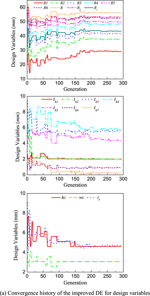
Download figure:
Standard image High-resolution image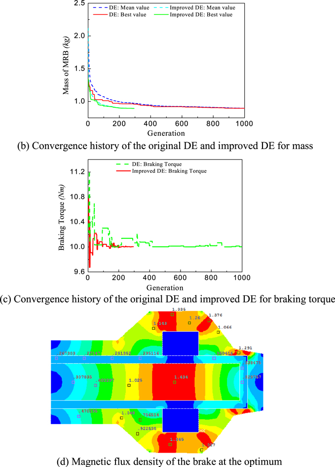
Figure 10. Optimization solution of the polygonal-shaped side-coil MRB.
Download figure:
Standard image High-resolution image
Table 6. Optimal design comparison for the polygonal-shaped side-coil MRB.
| Optimal design results | |||
|---|---|---|---|
| Design variables (mm) | First order [18] | DE | Improved DE |
| nwc(layers) | 5.1 (6) | 6 | 6 |
| nhc(layers) | 12.3 (10) | 11 | 9 |
| Rd | 52.4 (52.7) | 50.98 | 53.2 |
| td | 5.2 (4.9) | 5.22 | 4.71 |
| Rc | 40.1 (41.4) | 40.57 | 43.39 |
| R1 | 25.6 (27.45) | 26.61 | 29.16 |
| th1 | 2 (2) | 2.01 | 2 |
| R2 | 33.8 (36) | 34.72 | 37.69 |
| th2 | 3.1 (3.51) | 2 | 2 |
| R3 | 39 (41.26) | 38.81 | 41.69 |
| th3 | 5.23 (59.24) | 6.16 | 5.64 |
| R4 | 43.1 (44.15) | 46.85 | 48.44 |
| th4 | 5.58 (5.72) | 5.63 | 5.72 |
| R5 | 46.98 (47.16) | 48 | 49.88 |
| th5 | 5.24 (5.78) | 4.67 | 4.38 |
| R6 | 51.33 (51.1) | 50.58 | 52.48 |
| th6 | 1.02 (1.11)56.21 | 1.04 | 0.92 |
| R(R7) | (55.71) | 54.02 | 56.21 |
| th7 | 0.2 (0.16) | 0.24 | 0.23 |
| Mass of MRB (kg) | 0.963 (0.932) | 0.894 | 0.894 |
| Off-state torque (Nm) | 0.234 (0.234) | 0.223 | 0.236 |
| Number of coil turns | 61.7 (60) | 63 | 54 |
| Iteration/Generation | 60 [1500] | 1000 | 294 |
| Elapsed time (h) | 16.611 | 4.884 | |
In order to evaluate the benefits of the proposed optimization method for MRBs over other gradient-free global optimization, the optimal design of the MRBs using the genetic algorithm (GA) and particle swarm optimization (PSO) method are conducted and the results are presented in table 7. In setting of the GA and PSO, all parameters that impact significantly on the optimal search process such as population size, convergence rate and boundary of design variables are similar to those of the improved DE. To avoid prolixity, in this work, only rectangular-shaped MRB is considered. From the results, it can be seen that the optimal mass of the MRB gained by the improved DE is the smallest, while the optimal one obtained by the GA is the highest (1.291 kg for the improved DE, 1.318 kg for PSO and 1.355 kg for GA). The effectiveness of the improved DE in obtaining the global optimal results is validated in comparison with the GA and PSO. Moreover, the improved DE is outstanding with the GA and PSO in the number of analyses (97 generations for improved DE, 500 and 180 generations for the GA and PSO, respectively) and computation cost (1.159 h for the improved DE, 11 h and 2.833 h for the GA and PSO, respectively). Considering the compactness based on the MRB size (brake length and radius), the MRB configuration obtained by the improved DE is also better than those of others. In addition, the off-state torque of the MRB gained by the improved DE is slightly higher than the one of the GA, but lower than the one of the PSO. Generally, with the optimization problem investigated in this study, the improved DE can find MRB configurations that can be better than those of the GA and PSO, as well as having less computational cost than other global optimization methods.
Table 7. Optimal design comparison to other documented results.
| Rectangular-shaped conventional MRB | |||
|---|---|---|---|
| Parameters | Proposed | GA | PSO |
| Braking torque (Nm) | 10 | 10 | 10 |
| Off-state torque (Nm) | 0.137 | 0.132 | 0.143 |
| Brake length (mm) | 14.92 | 16.32 | 15.1 |
| Brake radius (mm) | 61.02 | 60 | 61.58 |
| Mass (kg) | 1.291 | 1.355 | 1.318 |
| Generation | 97 | 500 | 180 |
| Elapsed time (h) | 1.159 | 11 | 2.833 |
From the above, some advantages and conclusions of the proposed optimization procedure in the optimal design of MRBs can be summarized as follows:
- The values of the objective functions of the MRBs gained by the proposed optimization procedure are the global optimal solutions thanks to the robustness and reliability of the DE-based algorithm. It can be seen that the integrated methodology overcomes some disadvantages existing in ANSYS optimization tool related to the local optimal results and the infeasible solutions.
- Essential discrete variables can be taken into account in the optimal design of the MRBs in order to improve the accuracy and reliability of the results as well as to be able to apply the approach to a real-life design model.
- Based on the optimal results and the shortcomings in computation costs of the three optimization methods used in this research: first order and two DE-based algorithms, it can be seen that the improved DE is the most suitable one for solving the MRB optimal problems.
6. Conclusion
A new design optimization approach has been proposed for the optimal design of MRBs with different configurations. In this work, complex nonlinear FEAs of different MRBs are generated and merged with DE-based optimization algorithms to obtain the optimal solutions. The optimization problem examined is to minimize the mass of the brake, while the required braking is constrained to be greater than a given value. The mass of the MRBs achieved by both DE-based algorithms is better than the previous results using the first-order method in the ANSYS optimization tool. Moreover, the paper successfully illustrated the main advantages of two improvements of the DE, which lead to a significant decrease in the computational cost. In addition, the proposed optimization for the MRBs in this work can be performed with discrete design variables such as dimensions of coil. Finally, thanks to using an external optimization algorithm via programming in MATLAB, an effective integrated optimization procedure is established to overcome the current restrictions of the ANSYS optimization tool as well as those of other optimization methods for MRBs.
The method used in this study can be easily extended to the optimal design of MRBs with more complex objective functions and constraints. It can also be used for other problems with continuous and/or discrete design variables, especially for MRF-based systems.
Acknowledgments
This work was supported by the Vietnam National Foundation for Science and Technology Development (NAFOSTED) under Grant no. 107.01-2015.32.