
Abstract
A great many living beings, such as aquatics and arthropods, are equipped with highly sensitive flow sensors to help them survive in challenging environments. These sensors are excellent sources of inspiration for developing application-driven artificial flow sensors with high sensitivity and performance. This paper reviews the bio-inspirations on flow sensing in nature and the bio-mimicking efforts to emulate such sensing mechanisms in recent years. The natural flow sensing systems in aquatics and arthropods are reviewed to highlight inspirations at multiple levels such as morphology, sensing mechanism and information processing. Biomimetic hair flow sensors based on different sensing mechanisms and fabrication technologies are also reviewed to capture the recent accomplishments and to point out areas where further progress is necessary. Biomimetic flow sensors are still in their early stages. Further efforts are required to unveil the sensing mechanisms in the natural biological systems and to achieve multi-level bio-mimicking of the natural system to develop their artificial counterparts.
Export citation and abstract BibTeX RIS
1. Introduction
Flow sensing is an essential technique involved in numerous applications from traditional flow mapping to challenging turbulence characterization and liquid-dispensing, from maneuvering system of robots such as underwater autonomous vehicles (UAV) and self-stabilizing micro air vehicles (MAVs) to biochemical and biomedical applications. Such applications require that the flow sensors possess capabilities such as multi-dimensional mapping, low-detection threshold, short response time, least intrusion to the flow field of interests, and low costs and high durability (Chen et al 2003). Traditional flow sensing methods such as hot-wire anemometry (HWA), turbine flow meters, acoustic Doppler-shift velocimetry and particle image velocimetry (PIV) cannot fulfil these requirements due to their large size, low sensitivity, complex setup, etc (Fan et al 2002).
Nature has always been a source of inspiration and serves as a guide for technical developments (Fratzl and Barth 2009, Stroble et al 2009). Creatures live in different media, e.g., fish in the water, flies in the air, and earthworms in sand or mud. Some of these media are changing rapidly and, therefore, creatures in them are equipped with flow sensitive sensors in order to survive in these changing complex environments. It is inspiring to learn from nature and develop artificial counterparts that emulate such high-performance biological flow sensors.
Research on natural hair flow sensors has just begun and only a few attempts have been made to create biomimetic sensors. This paper intends to provide a comprehensive review on bio-inspired hair flow sensors, which includes the basic sensing mechanisms in biological hair flow sensors and what has been achieved on biomimetic devices to date. The bio-inspirations at different levels, namely hair morphology, sensing mechanism, information processing and so on, are highlighted to emphasize that only through a multi-level mimicking strategy can high performance be achieved in artificial hair flow sensors. Specifically, in the following sections we will discuss two unique types of biological hair flow sensors and the different approaches that realize bio-mimicking of such sensors.
2. Bio-inspiration: flow sensors in the nature
Flow sensors are ubiquitous in nature: Mexican blind fish rely on a lateral line system to navigate (von Campenhausen et al 1981); crickets escape from predators using the flow information provided by their hairy cerci (Tauber and Camhi 1995); caterpillars detect flying wasps by hairs sensitive to airborne disturbances(Tautz and Markl 1978); scorpions usually have patterned flow sensitive hair arrays on their pedipalps (Hoffmann 1967); and bats monitor flow conditions by wing hairs to support flight control (Sterbing-D'Angelo et al 2011). Among the various flow sensors in nature, the instinctive flow sensors of aquatics and arthropods are the most intensively studied. In this section, the morphology, function and biomechanics of the lateral line neuromasts of aquatics and the filiform hairs of arthropods are examined to shed light on the development of their artificial counterparts.
2.1. Lateral line system of aquatics
The lateral line (figure 1), which can be found in all cartilaginous and bony fish and aquatic amphibians, has been studied extensively in the past few decades as a spatially distributed system of directional flow sensors (Dijkgraaf 1963, Coombs 2001). Relying on the lateral line system, at least mainly relying on it, fish 'feel' low frequency (<200 Hz) water motions created either by steady flow or turbulent flow. This information is then processed by its central nervous system to guide a number of different behavioral abilities, such as orienting, schooling and preying (Coombs 2001).
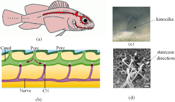
Figure 1. The lateral line system of fish. (a) Neuromasts distribution in Lake Michigan mottled sculpin, black dots in the red shaded canal area represent the CNs and dots in other areas are SNs (Reprinted with permission and modified from Coombs (2001)). Copyright 2008 Springer Science and Business Media). (b) The neuromasts canal diagram3, typically between an adjacent pore pair, there is one CN (CILIA 2008). (c) A SN with Cupula is examined optically and the kinocilia are visible (modified from McHenry and van Netten (2007); the kinocilia are highlighted in yellow for better illustration). (d) A neuromast of zebra fish (modified and reprinted with permission from Roberts et al 2009). This neuromast consist of seven hair cells and the white arrows indicate that the staircase directions for the two groups of hair bundles are nearly opposite.
Download figure:
Standard imageThe lateral line system is constituted by a number of neuromasts, which are the key sensory units in the system. The number of neuromasts varies in different species, from less than 100 to over 1000, and they are distributed spatially in the head, trunk and tail of the fish body (Schmitz et al 2008, Bleckmann 2008 and figure 1(a)). Neuromasts consist of receptor cells called hair cells, which are mechano-electrical transducers with directional sensitivities (Coombs 2001). A number of hair cells are encapsulated in a gelatinous cupula, which interacts with the surrounding fluid directly. Two major types of neuromasts exist. Superficial neuromasts (SNs) are those situated on the surface of the fish body and directly exposed to the external water flow (figure 1(c)), whereas the canal neuromasts (CNs) are those embedded in a canal structure, which is connected with the outside flow through distributed pores (CILIA 2008 and figure 1(b)).
2.1.1. Number and distribution of canal neuromasts (CNs) and superficial neuromasts (SNs).
Hair cell numbers in neuromasts vary greatly, but typically a SN contains tens of hair cells and a CN contains hundreds to thousands of hair cells (van Netten 2006). The numbers and distributions of SNs and CNs are believed to represent an adaption to a particular hydrodynamic environment. Still water habitats are often related to the supernumerary SNs, with widened canals and reduced canal lengths, while turbulent aquatic environments are often associated with fish with less SNs and narrower canals (Schellart 1992, Bleckmann 1994, Engelmann et al 2002). It is thought that adult fish, which have complete systems of lateral line canals, are capable of localizing the prey stimuli from spatial variations in the pressure gradients along the trunk (Coombs and Conley 1997a, 1997b, Curcic-Blake and van Netten 2006); on the other hand, larvae, which are much smaller than the scale of prey stimuli (Higham et al 2006) and on which only SNs exist, can detect only a wide range of flow velocities and the high variability in the frequency responses of their SNs may hinder their ability to sense spatial cues (van Trump and McHenry 2008).
To engineers, these findings can, of course, shed some light on the design of flow sensors for different applications. For instance, for steady flow applications we can learn more from the SNs, while for the turbulent sensing CNs-type design may be more suitable. However, recent detailed studies (Beckmann et al 2010, Klein et al 2011) found that the number of SNs did not clearly predict the hydrodynamic environment. Therefore, to further uncover the sensing mechanism of the lateral line system, more information about the detailed anatomy of the peripheral lateral line and the physiology of SNs and CNs, their cooperation and the processing of stimuli in the central nerve system are required (CILIA report 2008).
2.1.2. Directional sensitivity.
The directional sensitivity of the lateral line enables fish to locate stimulus sources. The directional sensitivity of a single neuromast is due to the staircase structure of the hair cell, in which a bundle of relatively short stereocilia with increasing heights is followed by a longer kinocilium (figure 1(d)). The direction of the bundle's staircase is along the long axis of the canal for CNs and parallel to the long cross-sectional axis of cupula (van Netten 2006), and SNs are oriented in a line which is either parallel or perpendicular to the nearby canal axis (Kroese and Schellart 1992). Depolarizing of the cell occurs when the stereociliary bundle bends towards the kinocilium, simultaneously with an increasing in the firing rate of afferent fibers, and vice versa (Coombs 2001). Along the intermediate directions, displacement of the stereociliary bundle results in responses that are an approximate cosine function of the input direction (Flock 1965). Since hair cells on each neuromast are oriented in two opposing directions (Coombs 2001), the overall directional sensitivity of a neuromast also follows a cosine function. This directional feature of the neuromasts, together with the distribution of neuromasts in different parts of the fish body, may form the mechanism of how fish determine the water-flow direction and even the regional hydrodynamic variations from different stimuli (Montgomery et al 2000). Furthermore, a recent study reveals that the existence of flush ridges around the stereotyped array of SNs in the cephalic lateral line of the surface-feeding killifish changes the hydrodynamic environment of the SNs and as a result modifies the directional receptive range of this species (Schwarz et al 2011). All such information has implications for the development of artificial flow sensors.
2.1.3. Flow sensing mechanism: experimental discoveries and biomechanical sensing model.
Due to differences in the morphology and hydrodynamic environment, CNs and SNs also differ from each other in terms of sensing mechanisms and functions.
2.1.3.1. Experimental findings
The firing rates of the afferent fibers are controlled by the displacements of the neuromasts (Flock 1965). When the hair bundles were displaced towards the kinocilium, the afferent firing rates increase and vice versa. Afferents can increase their firing rate in response to hydrodynamic deflections of a single neuromast (Catton et al 2007). The existence of the cupula couples the motion of the surrounding water to the underlying cilia through viscous forces (Coombs 2001). Kroese and van Netten (1987) reported that the neural response is proportional to the displacement of the cupula, and in the meantime, the displacement of the cupula is largely proportional to the velocity of the flowing water. Montgomery et al (2000) also established a linear relationship between the responses of the SNs of the eel and the different stimuli with variable flow velocities. These findings indicate that the neurophysiological response of a neuromast depends on the degree to which cupula mechanics permit the deflection of the kinocilia in response to the water flow (van Trump and McHenry 2008).
Due to the difference in the hydrodynamic environment where CNs and SNs are exposed, CNs act as a detector of water acceleration while SNs function as a detector of water velocity. This has been proved by the measurements of the motions of the cupula (van Netten and Kroese 1987), the canal fluid (Denton and Gray 1983) and the response properties of afferent fibers innervate CNs and SNs (Kroese and Schellart 1992, Voigt et al 2000). Biologists have developed theoretical models to unveil the mechanisms of the sensing abilities of the neuromasts and to study their underlying interactions with fluids (van Netten 2006 (CNs modeling); McHenry et al 2008 (SNs)). All of these theoretical analyses, which will be described in the next context, help to understand the basic sensing mechanism and can be referred to in the design of the artificial counterpart of the lateral line system.
2.1.3.2. Biomechanical model for CNs
The frequency response of the cupula of CNs of a ruff measured at the top and that measured at the base was reported as being identical to each other, which implies that the cupula is actually sliding over the sensory epithelium during motion (van Netten and Kroese 1987). Using laser interferometric techniques, the cupula and canal fluid dynamics have been determined with nanometer accuracy (reviewed by van Netten 2006). The response of a CN to the fluid flow was found to be dependent upon the frequency-dependent flow characteristics and the size and the stiffness of the cupula. From this result, biologists model the CNs as a rigid hemisphere sliding over a frictionless plate, which is coupled with a linear spring whose stiffness was provided by the underlying hair bundles (figure 2(a)(i), van Netten and Kroese 1987, van Netten 1991, 2006). In van Netten's model, the free stream in the canal is modeled as a uniform freestream since it is not greatly influenced by the boundary layer dynamics for the frequency band to which the CNs are sensitive (>20 Hz) (van Netten 2006). Furthermore, the uniform stream flow speed in the canal is proportional to the pressure difference between adjacent pores (Denton and Gray 1983, van Netten 2006).
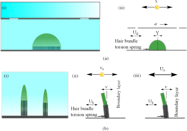
Figure 2. Schematic illustrations of CNs and SNs and their responses to hydrodynamic stimulus. (a)(i) is a CN between two adjacent pores; and (a)(ii) illustrates the modeling of the CN responding to a vibration-sphere-induced canal flow. The CN can be modeled as a sliding hemisphere, whose deflection (Y) is induced by the uniform canal flow (Uc).The stimulus is a vibrating sphere (with displacement X and frequency f), the resulting acceleration along the canal is a. (b)(i) shows two SNs exposed to the boundary layer near the fish skin. The color gradient of the flow (blue) illustrates the velocity profile in the boundary layer; (b)(ii) illustrates the response of a single SN to a near vibrating sphere. V0 is the vibrating velocity of the sphere, Uh is the local velocity in the boundary layer and ν is the deflection of the cupula at the height of the longest stereocilia (McHenry and van Netten 2007); b(iii) illustrates a model for a SN responding to a freestream (U0).
Download figure:
Standard imageRefer to figure 2(a)(ii), use the hemisphere as the subject, the governing equation for the dynamics of the CNs reads:


in which, on the left-hand side are the structural forces and on the right-hand side are the hydrodynamic forces. In detail,  is the structural inertial force of the hemisphere, where M and Y is the mass and the displacement of the CN, respectively; Fk = KY(t) is the structural stiffness resistance of the hemisphere due to the elastic coupling of the hair bundles to the epithelium, with K, the sliding stiffness, which is proportional to the number of hair cells;
 ![${F}_{\mathrm{u}}=D[\dot {Y}(t)-\dot {W}(t)]$](https://content.cld.iop.org/journals/0964-1726/21/11/113001/revision1/sms417332ieqn94.gif) is the hydrodynamic drag force acting on the hemisphere, here D is the drag coefficient, W is the displacement of the water; and
is the hydrodynamic drag force acting on the hemisphere, here D is the drag coefficient, W is the displacement of the water; and  is the buoyance force acting on the hemisphere due to the pressure differences around the structure.
Due to the linearity of the governing equation, the frequency-dependent cupula sensitivity (SY/U0(f)), which is defined as the ratio of displacement amplitude (Y0(f), which itself is a function of the stimuli frequency f) to the amplitude of excitatory fluid velocity (U0) can be obtained by solving the governing equation. The solution is given by (van Netten 2006):
in which  is the Reynolds number for periodic fluid flow and
  is defined as the transition frequency at which viscous (f < ft) or inertial (f > ft) fluid forces dominate the fluid forces action on the cupula, with ρ and a being the density of the water and the acceleration of the canal flow; and
  is defined as the resonance factor, which governs the resonance properties of a cupula, with μ being the dynamic viscosity of the water.
2.1.3.3. Biomechanical Model for SNs
In contrast to the CNs, SNs are driven by the external flow, which is governed by the boundary layer hydrodynamics over the surface of the body (Jielof et al 1952, Kuiper 1967, Hassan 1985, Kalmijn 1988, Dinklo 2005). McHenry and van Netten evaluated the flexural stiffness of SNs in the zebrafish lateral line and found that the flexural stiffness is proportional to the number of hair cells embedded in the cupula and the distal tip of the cupula is predicted to be at least an order of magnitude more flexible than the proximal region (McHenry and van Netten 2007). Consequently, they model the SNs as two joined beams of different flexural stiffness, whose base behaves as a pivot coupled to hair bundles that act as a spring (McHenry and van Netten 2007, McHenry et al 2008 and figure 2(b)). The structure is driven by the stimulus of an oscillating pressure field and its boundary layer over a flat plate (McHenry et al 2008). Similar to the CNs, the governing equation of motion for the cupula reads (McHenry et al 2008),

Different from the governing motion equation for the cupula of CNs, the governing equation is also a function of elevation z, since the bending of the beam results in varying forces at different elevations. On the left-hand side, the spring stiffness term Fk in CNs model is replaced by the elastic stiffness term Fe(z) in the SNs model; and on the right-hand side, there is one more term defined as acceleration reaction force, Fa, due to the relative acceleration of the flow and the cupula.
To evaluate the frequency response, a measure of sensitivity (McHenry et al 2008) is defined as the cupular deflection at the height of the tip of the tallest stereocilium, ν(hh), to the free stream velocity, U0:
where Cj is a sequence of four integration constants; hh is the height of the tip of the tallest stereocilium; EI is the bending modulus of the neuromasts;  ;
;  ;
;  is the viscous drag coefficient with
  , where γ is Euler's constant (γ ≈ 0.5772), d is the diameter of the cupula and δ is the boundary layer thickness with
  ; ρw and m are the density and dynamic viscosity of water, respectively; ρm is the density of the cupula matrix and ω is the angular speed of the stimulus.
2.1.3.4. Multi-layer filtering effect in CNs
Through modeling the responses of a CN or SN to their corresponding hydrodynamic environment, the sensitivity of the neuromasts in terms of their deflections to the flow velocity (SY/Uc, Sν/U0) can be analytically expressed, as shown in (3) and (5). Figures 3(b) and 4(b) plot examples of the deflection responses to flow.

Figure 3. Multiple-layer filtering of a CN to a vibrating sphere. (a) illustration of the multiple-level filtering of the CN system; (b) theoretical modeling of the dynamics response of the CN: Thicker solid line represents the sensitivity SY/a of CN deflection Y to the acceleration a of the flow in the surface of the canal (left axis); the thinner solid line represents the sensitivity Sa/X of surface flow acceleration a to the displacement of the vibrating sphere X (left axis); short dashes represent the sensitivity SUc/a of the canal flow velocity to the surface flow acceleration (right axis); and long dashes represent the sensitivity SY/Uc of the cupula displacement to the canal flow velocity (right axis). It can be seen that the flat low-pass response of SY/a is the product of the low-pass filter SUc/a and SY/Uc; (c) the predicted sensitivity of SY/X, which is the product of SUc/a, Sa/X and SY/Uc. (Figure modified from Sane and McHenry 2009.)
Download figure:
Standard image
Figure 4. Multi-layer filtering of a SN to a pressure-driven flow (b) and vibrating-sphere-induced flow (c). In (a), the filtering mechanism is illustrated; and in (b) and (c): the sensitivity, Sν/U0 (thicker solid line, band pass), of the cupula deflection ν to the freestream U0 is a combination of the boundary layer filtering effect (dashed line, high pass) and the flow structure interaction effect (thinner solid line, low pass); the sensitivity, Sν/V0 (thicker solid line), of cupula deflection ν to the displacement of the vibrating sphere V0, is a combination of the sphere-induced boundary layer (dashed line, two-gain response) and the flow structure interaction effect (thinner solid line, low pass). (Figure modified from McHenry et al 2008.)
Download figure:
Standard imageHowever, complex filtering strategies were found in the flow sensing system in fish, which is related to the propagation path of the external excitation as well as its interactions with the sensory organ. Explorations of the filters can guide the sensor design regarding frequency response. Assuming a fish was exposed to a dipole stimulus (vibrating sphere), which simulates an approaching prey activity, multi-layer filters from the dipole source to the CN or SN response can be determined using hydrodynamics and motion principles. This is elaborated in the following.
Figure 3(a) plots the propagation paths from the external excitation to CNs. In the first stage, the sphere vibration produces pressure differences between the pores of the canals. In the second stage, the pressure differences between the pores of the canals produce canal flow. In the third stage, the canal flow deflects the CN and produces neural responses.
The response function in the first stage, where sphere vibrating produces pressure differences between pores of the canal, can be defined as the ratio of the surface acceleration (a) to the vibrating amplitude of the sphere (X), noted as Sa/X. Sa/X can be easily obtained since the pressure field around a vibrating sphere is well understood based on the fundamental hydrodynamic theories (Stokes 1851, Harris and van Bergeijk 1962, Kalmijn 1988). With this theory, it can be derived that the acceleration of surface flow is proportional to the sphere's acceleration and the sensitivity Sa/X is a linear function of the stimulus frequency (figure 3(b)).
The response function in the second stage, where the surface acceleration produces the canal flow velocity, can be defined as the ratio of the surface acceleration to the velocity of the induced canal flow, noted as SUc/a. The sensitivity SUc/a can be analytically resolved through theories for flow through cylindrical pipe (Sexl 1930, Denton and Gray 1982, 1983, 1989, van Netten 2006). Figure 3(b) plots the schematic of the response function. As shown in figure 3(b), the canal serves as a low-pass filter of the surface acceleration. The physical mechanism is at low frequencies, the viscosity dominates the resistance to the flow and the velocity of the canal flow is proportional to the surface acceleration; at higher frequencies, the inertial forces of the fluid reduce the velocity in inverse proportion to frequency.
The response function in the third stage, where the canal flow produces cupula displacement, can be defined as the ratio of the cupula displacement (Y) to the canal flow velocity (Uc), denoted as SY/U. SY/U has been derived in (3). At low frequencies, viscous drag dominates the fluid force on the CN cupula, CN cupula can be regarded as a flow velocity sensor since the deflection of the cupula is in proportion to the velocity of flow in the canal; at higher frequency, however, the inertial forces drive the CN to resonate, causing an elevated sensitivity at such frequencies. Therefore, the interactions between canal flow and cupula produce low-pass filtering effects.
The combined canal and cupula filtering characteristics can be studied by employing a new sensitivity function SY/a, which is defined as the ratio of the cupula deflection (Y) to the surface acceleration (a) and is the product of SY/Uc and SUc/a (6). The combination of two low-pass filters is also a low-pass filter (figure 3(b)). Below the resonant frequency of the cupula, the cupula sensitivity SY/Uc increases with frequency while the canal sensitivity SUc/a reduces accordingly. The counter-acting trends of the two signals result in a constant sensitivity of the SY/a up to the cupula resonance frequency (∼115 Hz), which indicates that the cupula can serve as an acceleration sensor in the low-frequency range, which makes it a good infrasound listener.

The overall sensitivity SY/X, which is defined as the ratio of the cupula deflection (Y) to the sphere amplitude (X), depends on the multi-level filtering effect from the sphere, canal, and cupula. This combination sensitivity can be calculated analytically as the product of Sa/X, SUc/a and SY/Uc (Sane and McHenry 2009) (7) as well as measured neurophysiologically.

Afferent recording of the response of the CN (afferent action potentials) to the vibrating sphere agrees well with the predicted dynamics response (figure 3(c)) at frequencies up to the cut-off frequency (Sane and McHenry 2009). This reveals the remarkable congruence of neurophysiology and biomechanics and indicates that the dominant factor for the CN is the mechanical properties of the CN.
2.1.3.5. Multi-layer filtering effect in SNs
The frequency response of the SN to flow induced by different stimuli has been studied by researchers such as McHenry and his colleagues (McHenry et al 2008, Windsor and McHenry 2009). The overall responses are decided by factors such as fields stimulus hydrodynamics, the boundary layer and the fluid–cupula interactions.
Figure 4(a) plots the propagation paths from the flow disturbance to SN deflection. For both near-field spherical excitation and far-field freestream flow, the boundary layer plays an important role in determining the overall interactions between SN and copular responses.
From local flow to SN deflection, the sensitivity Sν/Uh can be defined as the ratio of deflection of the cupula at the elevation of the longest stereocilia (ν) to the local flow velocity (Uh). The sensitivity can be estimated by modeling the SN cupula–flow interaction. The responses are shown in figures 4(b) and (c). At low frequencies, the viscous forces dominate the hydrodynamic forces on the cupula and the cupula deflects in proportion to the local flow velocity, i.e. Sν/Uh is nearly a constant at low frequencies; at higher frequencies, the acceleration reaction and inertia of the cupula dominates, and the cupula deflects in proportion to the flow displacement. Thus, SN acts as a low-pass filter to the local flow.
As mentioned previously, the boundary layer plays an important role in the SN response. The properties of the boundary layers (e.g. boundary layer thickness) are different due to different types of stimulus. To a pressure-driven flow, the sensitivity SUh/U0 (defined as the ratio of the local flow velocity at the tip of the stereocilia, Uh, to the free stream velocity, U0) can be regarded as a measure of these changes of boundary layer property. Also, SUh/U0 can be obtained by the well-established hydrodynamic theory (Batchelor 1967, Schlichting and Kestin 1979). The result show the boundary layer behaves as a low-pass filter (with cut-off frequency of the order of several thousand hertz).
To a vibrating-sphere-induced oscillatory flow, the boundary layer between the sphere and the skin where SNs are located is more complex. At low frequencies, the velocity near the skin is large since the sphere carries a large volume of fluid viscously; at higher frequencies, the vibration of the sphere reduces to a dipole source and the velocity is proportional to  , where rstimulus is the radius of the sphere and dstimulus is the distance from the sphere. Thus, the sensitivity SUh/U0, which is the ratio of the local flow to the velocity of the sphere, represents a two-gain response and has a greater sensitivity at lower frequencies.


The overall sensitivities of the SN to the stimulus can be expressed as the ratio of the cupula deflection to the freestream velocity for pressure-driven flow (i.e., Sν/U0 in equation (8)) or sphere displacement for vibrating-sphere-induced flow (i.e., Sν/V0 in equation (9)). For the pressure-driven flow, the combination of a low-pass filter (cupula) and a high-pass filter (boundary layer) results in a band-pass filtering effect, in which the boundary layer high-pass filtering effect dominates the change of sensitivity Sν/U0 at low frequencies. For the sphere-induced flow, a cupula is most sensitive to the oscillations of a sphere at low frequencies and the sensitivity attenuates throughout the frequency range. For larger diameter spheres, there exists a flat response region in the low-frequency range, which is due to the influence of the boundary layer between the skin and the sphere.
From the above discussions, it is clear that the sensitivity of a CN mainly depends on the canal hydrodynamics and the fluid–cupula interaction; while the sensitivity of a SN depends critically on the stimulus hydrodynamics, the boundary layer, and the fluid–cupula interaction. The variations in morphology of CNs and SNs in aquatics may imply that such variations enable them to be sensitive to a wide range of frequencies. Analogously, a proper design of the morphology of individual artificial neuromasts may tune the whole sensing system over a wide bandwidth.
2.2. Hair flow sensors in arthropods (crickets and spiders)
Similar to aquatics, terrestrial arthropods have also developed mature and nearly perfect flow sensors through thousands of years of evolution. Different from the lateral line neuromasts, however, the flow sensors in terrestrial arthropods are designed for wind or air flow. Some hair-like structures found in crickets, cockroaches, caterpillars, spiders and scorpions serve as flow sensors (Humphrey et al 1993). Among them, filiform hairs of cricket's cerci and trichobothria of spiders are studied most extensively (figure 5). This section illustrates the morphology and functions of such flow sensors. While the discussion is mostly based on the filiform hairs of crickets and trichobothria of spiders, nevertheless, it covers a few common features in flow sensing mechanisms.
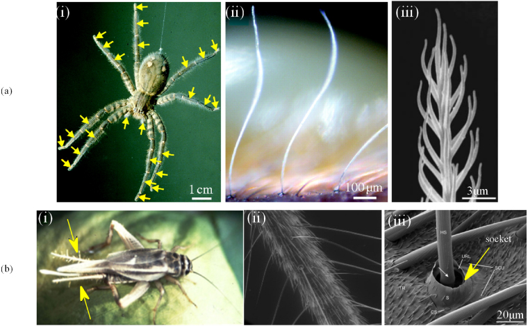
Figure 5. Multi-scale illustration of flow sensors in arthropods. (a) The trichobothria of spiders: (i) a female Cupiennius Salei. The arrows indicate the leg segments carrying trichobothria; (ii) a trichobothria array illustrating the high-aspect-ratio trichobothria shaft and its bent nature; (iii) the feathery surface structure of hair shaft. (b) The cercal system of crickets: (i) a female Acheta domestica, the arrows indicate the cerci covered with filiform hairs; (ii) a closer look at a section of the cercus with better illustration of the filiform hairs; (iii) the FESEM of the cuticular socket where the filiform hairs are located. (a(i)–a(iii) are adopted from McConney et al 2009c, b(i) and b(ii) from Jacobs et al 2008 and b(iii) from Heusslein et al 2009. Reprinted with permission from Springer Science and Business Media, Copyright 2009).
Download figure:
Standard imageSpiders' trichobothria and crickets' filiform hairs are known as one of the most sensitive biological sensors in terms of absolute sensitivities (Fratzl and Barth 2009, Barth 2004, 2002, 2000). The work needed to drive the hair shaft to deflect enough to elicit an action potential is only on the order of 10−20 J for a trichobothrium (Barth 2002), and even 10−21 J for a filiform hair in cricket (Thurm 1982a, 1982b, Shimozawa et al 2003). This corresponds to 1/100 of the energy of a single photon (Barth 2002). This absolute sensitivity enables the sensilla to work near the thermal noise of Brownian motion (Barth 2004). Figure 5 shows the multi-scale structures of the trichobothria of spiders and filiform hairs on the cerci of crickets.
2.2.1. Number, Morphology, and suspension properties.
Trichobothria and filiform hairs on the cerci of crickets are abundant in number and different in length (figures 5(a)(ii) and (b)(ii)). The number of trichobothria on spider legs are different depending on the size and species of the spiders, it ranges from several (7–11) to about 100 on each of spider's legs; the lengths of these hairs varies between 100 and 1400 μm in Cupiennius Salei and they are 5–15 μm (diameter) wide at the base, which means an aspect ratio of about 20–100 (Barth et al 1993). On the other hand, on the approximately 1 cm long cercus in a normal adult cricket Acheta domestica, there are approximately 750 filiform hairs (Jacobs et al 2008); in wood crickets, the filiform hairs can reach densities as high as 400 hairs mm−2 (Dangles et al 2006); the lengths of these hairs range from less than 50 μm to about 1500 μm for filiform hairs (Landolfa and Miller 1995). Although there are extreme hair sensor lengths up to 2500 and 3000 μm in arachnids and crickets, respectively (Casas and Dangles 2010), the lengths of these flow sensilla are typically in a limited range. The variations and limited range in lengths can be explained to some extent by the physical interactions between the air and hairs (Casas and Dangles 2010). The variation in length is the easiest way for arthropods to tune themselves to a certain frequency range of stimuli; and this limited range, in fact, is related to the boundary layer thickness near the platform where the hairs are positioned.
In some species of spiders, such as Cupiennius Salei, the trichobothria have a conspicuously sculptured or feathery surface (figure 5(a)(iii), McConney et al 2009c). This particular surface structure is believed to be responsive to the increase of the viscous drag from the surrounding air, as well as to the lightweight design of a trichobothrium, since it breaks up a solid volume into a feathery structure (Barth 2000).
All the sensory hairs are situated in the cuticular sockets (or cutiular cup). The viscoelastic suspension coupling the inner end of the hair shaft to the dendrites works as a combination of a spring and a dashpot. It provides the resistance to the deflection of the hair (figure 5(b)(iii)). The spring stiffness S is on the order of 10−11–10−12 N m rad −1, and the damping coefficient R in the order of 10−14–10−15 Nm s rad −1. (Barth et al 1993, McConney et al 2009c) (note: these values for S and R are obtained by the back-analysis method, in which their models were applied to the experimental data and the S and R values were back calculated). These extremely small constants lead the hair shaft to pure tilt without bending when driven by the viscous force of air (Fratzl and Barth 2009).
The significance of the hair number, morphology, and the viscoelastic properties of the socket material on the sensitivity and performance of the hairs will be demonstrated by the biomechanics modeling.
2.2.2. Biomechanics of filiform hairs and trichobothria.
The lightweight hair is driven by the frictional force of the air and the tilting deflection of the outer hair causes the embedded section to deflect and stimulate the neuron. This lever system scales down the deflection at hair tips through rotation (more than 1000:1) and scales up the force at the same factor (Humphrey and Barth 2007).
Mathematical modeling of the filiform hairs has received comprehensive exploration in the past few decades (Tautz 1977, 1979, Flecher 1978, Shimozawa and Kanou 1984a, 1984b, 1984c, Kamper and Kleindienst 1990, Humphrey et al 1993, Humphrey and Barth 2007, McConney et al 2009c). These models differ from each other in the different treatments of the driven forces on the hair shaft and the differences in choosing suspension resistance models (two-element system or three-element system). The details of each modeling are not duplicated here, and for further information the readers are referred to the literature mentioned above. In this work, however, we introduce the modeling method reviewed by Humphrey and Barth (2007). In this model, the filiform hair is modeled as a straight solid cylinder, which is pivoted in the base (as illustrated in figure 6).
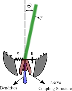
Figure 6. Schematic illustration of the modeling of a single filiform or trichobothria. The hair shaft was tilted by an angular deflection θ due to the torque T, which is resisted by the spring S and dash pot R in the socket material and the nerve coupling structures beneath it. The movement is conducted to the dendrites, which send the action potential to the CNS.
Download figure:
Standard imageThe cylinder rotates with small deflections (θ < 10°) about its resting position, which is perpendicular to the surface, due to the flow-induced torque. These deflections are resisted by the spring S and dashpot R in the pivot base. The Reynolds number of the cylinder is assumed to be much less than one, a condition such that Stoke's theory applies.
The equation of motion is obtained by the conservation of the angular momentum for the hair about the pivot point (10).

in which I is the moment inertia of the hair; S and R are the spring constant and the damping constant, respectively; θ is the angular displacement and T is the total torque acting along the hair. The total torque is caused by three types of forces (11), namely, Fu, Fa, and Fb, which are due to the viscous drag, the added mass of air around the hair, and a 'pressure gradient' force, respectively. Due to the distributed nature of these force terms, the total torque is calculated by integrating along the length of the hair (L0) (Humphrey and Barth 2007), i.e.
where l is the moment arm to the pivot point.
The flow velocity distribution along the hair shaft has been analytically obtained (Humphrey et al 1993). In the modeling, the hair substrate is modeled as a cylindrically shaped spider leg or cricket cercus and the hair shaft is both modeled for conditions where the shaft is either perpendicular or parallel to the hair substrate (see Humphrey et al 1993). In practice, flow past the spider legs or cricket cercus can be approximated as flow oscillating over a flat surface (Humphrey and Barth 2007), which yields, according to Panton (1996):

In equation (12), U0 and ω denote the far-field velocity amplitude and angular frequency, respectively; y is the distance from the flat surface,  is a system parameter and ρair is the density of the air.
With equations (11) and (12), the steady solution of equation (10) can be analytically obtained. The readers are advised to refer to Humphrey et al (1993) for the detailed methodology and solutions; and to Humphrey et al (2001) for expressions of the maximum angular displacement, the maximum angular velocity and the maximum angular acceleration.
2.2.3. Sensitivity.
Based on the mathematical modeling, the sensitivity of a filiform hair to different stimuli can be easily analyzed. The effect of hair geometry (d,L) and suspension properties (S,R) on the sensitivity of hairs have been studied by Humphrey and his co-workers (Humphrey et al 1993, Humphrey and Barth 2007). It was found that with increasing hair lengths, the maximum angular displacement, maximum angular velocity and maximum angular acceleration ( ,
,  , and
, and  ) increase and the hair resonance frequency decreases. At low frequencies, long and middle length hairs are good sensors for displacement and velocity; while at higher frequencies, middle length and short hairs are good indicators for velocity and acceleration. More interestingly, the trends of the sensitivities for long hair and short hair are opposite in a particular frequency range. That is, in the region where the sensitivity of the long hair drops off, the short hair may compensate since its sensitivity in this region increases (Humphrey et al 1993). This character enables a hair array with different lengths to cover a larger frequency range with high sensitivity and, theoretically, a spectral analysis of a stimulus can be retrieved through the responses of a hair array (Barth 2004).
The properties of the viscoelastic suspension will also influence the performance of the hair sensors. In general, with a fixed spring constant S, increasing damping R results in a decrease of the  ,
,  , and
, and  at all frequencies; On the other hand, with a fixed damping R, an increasing spring constant S results in a decrease of these quantities, but only up to a certain frequency, beyond which, however, the effect is reversed (Humphrey et al 1993).
Since the S and R constants only vary in a very small range for particular species of arthropods, variations in the length of the hairs may be the most effective way to adjust the frequency response. Therefore, for a corresponding artificial sensor system, one would primarily change L0 to modify or adjust the tuning in the system (Barth 2002).
3. Bio-mimicking: artificial hair flow sensors
Through the review on the biological hair flow sensors in the previous context, we learn that the aquatics and arthropods are enabled to not only 'feel' the flow, but also 'listen' to particular frequency bands, and filter noisy or unwanted signals. This capability is attributed to the hair or hair-like structures, which have attracted a much interest from researchers in constructing artificial counterparts. In this section, we try to provide a state-of-knowledge review on the development of bio-inspired hair flow sensors, including the design, fabrication, performance and packaging of such sensors. Comparisons are also conducted on these sensors and discussions are delivered. The review is restricted to the mimicking of the high-aspect-ratio hair-like sensing structures. MEMS flow sensors with high spatial and temporal resolutions have also been designed and fabricated, however, without mimicking the high-aspect-ratio hair-like structures. This is beyond the scope of this paper and the readers are referred to Chen et al (2007) for further information.
Based on the sensing principles or readout mechanisms, the biomimetic hair flow sensors are categorized into several groups, namely, thermal, piezoresistive, capacitive, magnetic, piezoelectric and optical sensors. Flow sensors based on thermal principles such as hot-wire anemometry (HWA) have been well studied and commercialized in the past decades. In such sensors, a thermal element serves both as a heater and a temperature sensor when in operation. The temperature of the thermal element will change when flow passes it and the changes of temperature indicate the cooling rate and the flow velocity (Chen et al 2003). An array of MEMS HWA was studied recently for hydrodynamic object tracking or underwater dipole localization and such a system has been termed an artificial lateral line system (Chen et al 2006a, Pandya et al 2006, 2007, Yang et al 2006, 2010). Although at the level of array layout, it mimics the lateral line system, at the level of single sensors, it shares few common properties with biological hair sensors due to the disparate sensing principles. The detailed description of the single HWA sensor are not duplicated here and the array level processing algorithm of such arrays are discussed in section 3.1.
MEMS-based biomimetic flow sensors have also also briefly reviewed by Zhou and Liu (2008). In this section, we discuss in detail bio-inspired hair sensors based on different sensing principles. Biomimetic hair flow sensors (BHFS) sensors based on piezoresistive and capacitive principles are among the most mature sensors and therefore we discuss these types of sensors in great detail. Biomimetic hair flow sensors with other readout systems are also briefly reviewed in order to inspire further interest in such areas.
3.1. Piezoresistive BHFS
Piezoresistive sensing is commonly used in engineering and the most common case is the piezoresistive strain gauge. The mechanical deformation can be measured by the change of electrical resistance of the piezoresistive sensor ( , where Rp is the electrical resistance and ε is the strain). Artificial hair flow sensors with different designs are fabricated and characterized by the MedX Lab in Northwestern University under the DARPA BioSenSe program. Their designs are mostly inspired by hair cells in nature (reviewed by Liu 2007 for their previous achievements), especially the neuromasts in the lateral line system.
Three components constitute the functional structure of the piezoresistive BHFS from the MedX Lab: a vertical hair-like structure, an in-plane cantilever and a silicon resistor (figure 7). The principle of the piezoresistive BHFS is straightforward: the hair structure rigidly connects at the far end of the cantilever; flow-induced drag forces drive the hair shaft to deflect; the moment transfers to the lateral cantilever, which deflects simultaneously with the hair shaft; the deformation at the base of the cantilever can be monitored using the piezoresistor. The deformation-induced changes of resistance can be easily measured with an on-chip or external Wheatstone bridge.
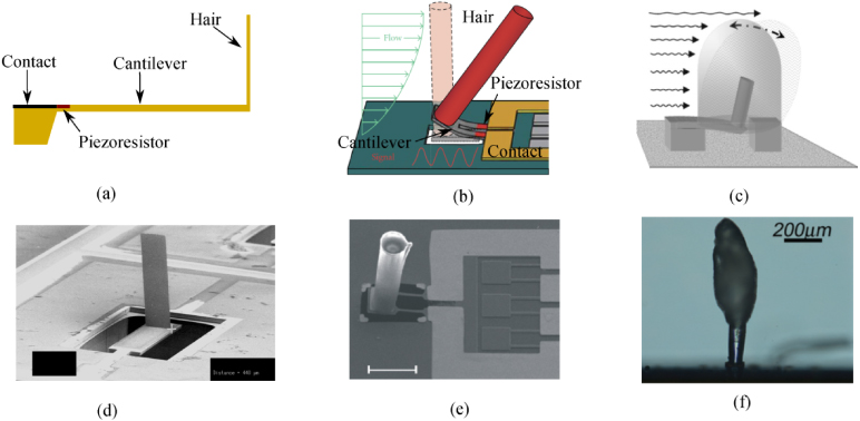
Figure 7. Piezoresistance-based MEMS hair sensors from the MedX Lab. Schematic drawings of the first design (a), second design (b) and third design (c) of a single sensor, and the corresponding SEM pictures (d), (e) and (f), respectively. The hair of the first design was made of metal or metal/Permalloy, and was replaced with SU-8 hair in the second design. A layer of hydrogel 'cupula' covered the SU-8 hair to form the sensor of the third design. Figures are adapted from Fan et al 2002 ((a) and (d)), Nguyen et al 2011 (b), Yang et al 2011, reprinted with permission from American Institute of Physics, Copyright 2011, (e), Peleshanko et al 2007 (c), reprinted with permission from Wiley and Sons, Copyright 2007, and McConney et al 2009b (f).
Download figure:
Standard imageThe MedX Lab proposed three different designs of the BHFS utilizing different materials and different fabrication methods for the hair structure (figure 7). In the first design (figures 7(a) and (d)), the vertical cilium is made of a gold–permalloy composite and realized using a three-dimensional assembly technique called plastic deformation magnetic assembly (PDMA). The piezoresistor and the lateral cantilever beam were fabricated using doping and etching techniques, respectively. Before the PDMA process, a sacrificial layer of copper and a thin layer of gold are deposited and patterned using photolithographic methods, followed by a deposition of the layer of Permalloy material. The copper layer is then removed with diluted HCl solutions and the freed gold–permalloy composite cantilever is exposed to a high magnetic field. The cantilever is then rotated off the substrate due to the magnetic force. Plastic deformation of the gold ensures that the cantilever remains at a certain angle (e.g. 90°), which can be controlled by choosing a certain geometry of the cantilever and the magnetic field. To define a specific bend region and reduce the stress concentration at that region, the electroless plating method is used to enhance the bend region. This treatment leads to a significant yield of assembly. The fabricated device is also coated with a uniform Parylene layer for strengthening and electrical insulation (Li et al 2002, Fan et al 2002). To increase the robustness of the device, polymer substrate is used instead of silicon (Chen et al 2003). In the latter design, the vertical hair is rigidly attached to the substrate, the lateral cantilever is omitted and the strain gauge is attached at the base of the hair. The vertical hair is also realized using the PDMA process and the difference is that the cantilever is based on a layer of polyimide (Chen et al 2003) instead of silicon. The details of fabrication and performance of the MedX Lad's first design of the MEMS hair flow sensors are also reviewed by Nawi et al (2011).
In the MedX Lab's second design, the hair structure is made of SU-8 and the circular high-aspect-ratio SU-8 hairs are realized using spin process and photolithography methods (figures 7(b) and (e)). In fact, PDMA process is based on the surface micromachining, which limits the structure to be asymmetric (e.g. rectangle in the first design). Therefore the MedX Lab's first design poses limitation on the spatial resolution. In its second design, the spatial resolution is improved since the hair structure is in a symmetric circular shape. The piezoresistors and the corresponding on-chip Wheatstone bridge resistors for the second design are achieved by ion implantation. After the vertical hair assembly, the devices are released in buffered oxide etch to free the lateral cantilever (Chen et al 2006b, 2007, Tucker et al 2006). In the whole fabrication process, the SU-8 step is the only step which is not standard, since the SU-8 is very sensitive to processing parameters; however, the SU-8 process minimized manual handling of the devices during fabrication and thus improves the yield and enables array fabrication (Chen et al 2006b, 2007).
In the MedX Lab's third design, an artificial cupula is fabricated to encapsulate the SU-8 hair. As described in the previous review, for the neuromasts in the lateral line system, the cupula plays an essential role in the sensitivity of the neuromasts. The cupula is very flexible in nature (McHenry and van Netten 2007) and it couples the neuromast hairs to the surrounding hydrodynamic environment, maximizing and mediating drag forces (Peleshanko et al 2007). Inspired by the cupula of neuromasts, a combined hybrid soft–hard material design of the micro-flow-sensor is introduced and a hydrogel cupula grown on the SU-8 hair of the second design is realized by a wet-chemistry micropatterned photopolymerization method (Peleshanko et al 2007). The key process of the cupula encapsulation includes the spreading of the water-soluble polyethylene glycol (PEG) monomer, the patterned photopolymerizing through UV photo-crosslinking, the removing of the non-reacted monomer layer and the swelling of the PEG layer using water (Peleshanko et al 2007). The achieved cupula using this technique is dome shaped and extends the SU-8 hair by 30%–40% in height and by 10–20-fold in diameter. In order to achieve a high-aspect-ratio cupula, which mimics the superficial neuromast cupula, an alternative approach is utilized. Droplets of poly(ethylene glycol) tetraacrylate (PEG-TA) are dispensed from a syringe and manually deposited on to the SU-8 hair. The realized cupula starts from the midpoint of the SU-8 hair and extends the hair by 50%, which is a good balance between robustness, height and preventing wetting of the platform (McConney et al 2009b). The elastic modulus of the artificial cupula is within 8–10 kPa (Peleshanko et al 2007) or of the order of 10 Pa (McConney et al 2007), which is similar to their biological counterparts.
Systematic characterization of the MedX Lab's piezoresistive flow sensors showed high flow sensitivity and angular sensitivity both underwater and in air (Chen et al 2007). The gauge factor of the second design can reach 33.6–78.9 (Chen et al 2006b, 2007). The sensitivity of 100 mm s−1 in a water tunnel is reported for the first design (Fan et al 2002); a sensitivity increased to below 1 mm s−1 in water (0.1 mm s−1 is also reported by Tucker et al 2006) for the second design (Chen et al 2007); with the artificial cupula the sensitivity is further increased by 10–40-fold (Peleshanko et al 2007, McConney et al 2009b). This sensitivity is compatible with that of neuromasts of the lateral line system. The off-axis rejection ratio in the second and third designs is as high as approximately 17.5:1, which shows a high degree of directional sensitivity (Chen et al 2007). A wind tunnel directionality test demonstrates a clear 'figure of eight' sensitivity pattern on the polar plot and an angular resolution of 2.16° in air is achieved (Chen et al 2007).
Besides the group mentioned above, there are also several groups who take the advantage of piezoresistive principle to mimic the functions of biological hair flow sensors. Ozaki et al (2000) proposed two types of air flow sensors inspired by the wind receptor of insects. Both designs applied the piezoresistive principle. Their 1-DOF sensor consists of an array of planar cantilevers with strain gauges on the base and the 2-DOF sensor consists of a cantilever fixed on a cross-shaped beam with strain gauges in each direction. The same principle as the Ozaki's 1-DOF sensor was also adopted by Wang et al (2007), Zhang et al (2008), Du et al (2009), Aiyar et al (2009), Song et al (2011) and Qualtieri et al (2011). The differences of such sensors lie in the material and machining techniques, geometries and the sensitivity. The principle of Ozaki's 2-DOF sensor was also employed by other researchers (Xue et al 2007, Zhang et al 2008 and Wang et al 2008). Table 1 provides a summary to compare the fabrication and performance of these different sensors. All these designs adopted symmetric or circular cantilevers and enable the capability for bi-directional flow sensing benefiting from the four orthogonally arranged piezoresistive strain gauges. Among these designs, some of them are not designed for flow sensing but rather for tactile sensing (Engel et al 2005, Hu et al 2010) or pressure sensing (Xue et al 2007 and Zhang et al 2008), but they also have the potential to be redesigned as flow sensors. It is worth noting that some of these sensors are all-polymer based, and showed the capability to use flexible substrates or to be integrated with flexible PCBs (Engel et al 2005, Aiyar et al 2009 and Song et al 2011).
Table 1. Summary of different designs of piezoresistance-based MEMS BHFS (Note: the geometries appeared here are only for the sensors appearing in corresponding literature. The techniques are not limited to such geometries, though.)
| Design | Piezoresistance material | Hair material | Hair method | Hair geometrya | Note |
|---|---|---|---|---|---|
| MedX Lab 1st (Fan et al 2002) | Boron ion diffused Si | Metal/polymer–permalloy | PDMA | 820–1100 μm × 100–200 μm × 10 μm | Sensitivity: 100 mm s −1 |
| MedX Lab 2nd (Chen et al 2007) | Boron ion diffused Si | SU-8 | Photolithography | 600 μm × ∅80 μm | Sensitivity: 0.1 mm s −1 |
| MedX Lab 3rd (Peleshanko et al 2007, McConney et al 2009b) | Boron ion diffused Si | SU-8-hydrogel | PEG deposition/photo-crosslinking | dome: 500–1000 μm × ∅1000–2000 μm ; high-aspect-ratio: 800 μm × ∅O (100 μm ) | Sensitivity: 75 mm s −1 (dome) 2.5 mm s −1 (high-aspect-ratio) |
| Ozaki 2-DOF | Boron ion diffused Si | Wire of unknown material | Manual bonding | 3000 μm × ∅500 μm | Range: O (0.1) m s −1–2 m s −1 |
| Engel et al (2005) | Carbon-impregnated polyurethane | Polyurethane | Micro-molding | 3000 μm orthogonal | Used as tactile sensor |
| Xue et al (2007), Zhang et al (2008) | Boron ion diffused Si | Rigid plastic | Manual bonding | 5000 μm × 200 μm | Used as hydrophone |
| Wang et al (2008) | Platinum | NA | NA | NA | Range: 15–30 m s −1 |
| Hu et al (2010) | Poly-silicon | Silicon post | Etching | ∼3000 μm × 320 μm | Used as Tactile sensor |
| Ozaki 1-DOF | Boron ion diffused Si | Silicon nitride | Etching | 400–800 μm × 230 μm | Range: O(0.1) m s −1–2 m s −1 |
| Wang et al (2007) | Platinum | Silicon nitride | Etching | 4000 μm × 400–2000 μm | Range: 5–45 m s −1 |
| Du et al (2009) | Platinum | Silicon nitride | Etching | 3000 μm × 2500 μm | Range: up to 18 m s −1 |
| Aiyar et al (2009, 2011) | Elastosil® | Kapton® | Laser planar micromachining | 1500 μm × 400 μm | Range: up to 16.9 m s −1 |
| Zhang et al (2010) | Silicon | Silicon dioxide | Dry etching | 100–400 μm × 20–40 μm × 0.8 μm | Range: 0–0.2 m s −1 |
| Qualtieri et al (2011) | Aluminum Ni/molybdenum | Nichrome alloy | Etching | 200–600 μm × 100 μm |
aThe geometry is expressed by a product : length × width (or radius) ( × thickness).
3.2. Capacitive BHFS
Capacitive readout ( , where C is the capacitance, εm is the permeability of the medium between two parallel plates, the d∥ is the distance and A is the overlapping area) is widely used in many different types of sensors due to its high sensitivity and low power dissipation (for designs and applications of capacitive sensors, the readers are referred to Baxter 1997, Ghafar-Zadeh and Sawan 2010). Several research groups have developed sophisticated BHFS prototypes based on capacitive principles.
The Transducers Science and Technology group within MESA+ Institute for Nanotechnology in University of Twente, Netherlands is one major player in developing capacitance-based artificial hairs inspired by cerci of crickets. Several designs of BHFS/array with high sensitivity have been fabricated using advanced MEMS techniques. The characteristics of different designs are the improvements in its geometry optimization and fabrication processes. The detailed fabrication processes are not elaborated here. Only the principle of operation for these sensors is briefly described.
In Twente's designs, each artificial hair is situated at the center of a suspended membrane and a capacitor is formed by the top electrodes deposited on the suspended membrane and the bottom electrode on the base of the substrate. A schematic drawing of such sensors is illustrated in figure 8(a). Flow-induced tilting of the hair is resisted by the torsional stiffness of the membrane, whose deflection will result in a change of the capacitances of the sensor.
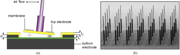
Figure 8. The schematic drawing of the capacitive hair sensors (a) and an example of fabricated sensor array (b). The hair is made of SU-8, which can be coated and exposed as multiple layers; the membrane and the wafer bottom form a variable capacitor. Figures are adapted from Bruinink et al (2009).
Download figure:
Standard imageIn Twente's first sensor design (van Baar et al 2003), the hair is made of SixNy and the membrane is suspended either with spirals running around or with the so-called double-gimbal suspension consisting of orthogonal torsional springs (figure 9(a)). The fabrication is monolithic and is realized through a combined bulk/surface micromachining process (van Baar et al 2003).
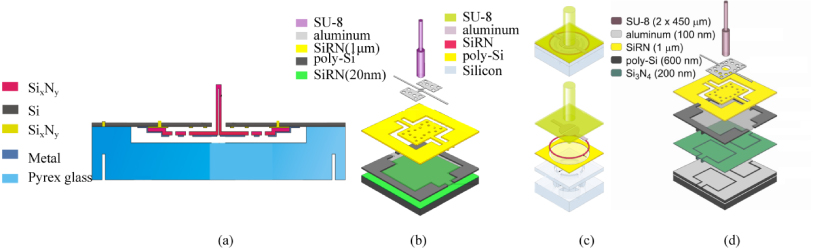
Figure 9. Different designs of capacitive hair sensors: The first design was monolithically fabricated and the hair was made of SixNy (a); from the second design (b) on, the hairs are made of SU-8; the membrane is fully supported and made of SU-8 in the third design (c), which is different from the other designs; in the fourth design (d), the bottom electrodes are fabricated separately using a SOI (silicon-on-insulator) technique. The figures are adapted from van Baar et al (2003) (a), Dijkstra et al (2005) (b), Izadi et al (2010) (c) and Dagamseh et al (2010a) (d).
Download figure:
Standard imageIn Twente's later design, the sacrificial poly-silicon-based readout structures, i.e., the membrane capacitors are first fabricated using surface micromachining technologies and the hair structures are realized by illuminating a layer of SU-8 photoresist, which is previously spin-coated on top of the membrane structure (figure 9(b), Dijkstra et al 2005). Using multiple layers and multiple exposures of SU-8 can increase the hair length up to and above 1mm with several segments stacked on each other (Krijnen et al 2006). In order to eliminate the curvature effect of the membrane due to the tensile stress in the electrode thin layer (chromium), the electrode thickness and length are reduced to obtain maximum sensitivity (Izadi et al 2007a, 2007b). Further modifications of several parts of the flow sensor, such as the hair length, the inter-electrode gap, the membrane shape and torsion beam geometries result in a 100-fold increase in sensitivity in capturing the flow amplitude, on the order of 1 mm s−1 (Bruinink et al 2009, Jaganatharaja et al 2009). We call such designs as Twente's second design of the capacitive BHFS.
To extend the sensors to liquid flow, the capacitive sensors are further refined to Twente's third design. In this design, the torsional SixNy membrane is replaced with fully supported flexible SU-8 thin membrane and the electrodes are insulated from liquid to prevent any short circuit (figure 9(c), Izadi et al 2010).
In the first three designs of capacitive sensors, an array of hairs shares a common bottom electrode and thus prevents wafer-scale array addressing. To enable fabrication of independent sensing electrodes, the silicon-on-insulator (SOI) wafer technology was utilized (figure 9(d)). This enables individual array element measurent and the frequency division multiplexing (FDM) is interfaced to realize array addressing (Dagamseh et al 2011). This design is termed as Twente's fourth design of the capacitance-based hair flow sensor.
The response of the capacitive sensors can be modeled as a three-tier system consisting of the mechanical system of the torsional suspended hair, the aerodynamic system and the capacitive transducer system (Krijnen et al 2007b). The performance of the sensors is evaluated by the figure of merit (FOM), which is defined as the product of usable bandwidth and sensitivity. It is shown that in order to obtain a high FOM, long thin hair made of low density with a small torsion stiffness is required. Although the authors mentioned that combining many hairs with different geometries would create a sensitive sensory system with relatively balanced frequency spectrum (Krijnen et al 2007b), no systematic analyses on this topic have been conducted. Instead, the researchers focus on the electrostatic spring softening effect by DC-biasing or AC-biasing in order to adaptively change the effective properties of the sensors (Krijnen et al 2006, Floris et al 2007, Wiegerink et al 2007, Izadi et al 2007a, 2007b, Krijnen et al 2007a, Droogendijk and Krijnen 2010, Droogendijk et al 2011, 2012). Based on the capacitive transduction theory, both the effective spring stiffness and the resonant frequency of the sensor will decrease with increasing bias voltage (Wiegerink et al 2007, Krijnen et al 2007a).
Table 2 summarizes the major characteristics of capacitance-based BHFS from this group.
Table 2. Summary of different designs of capacitance-based BHFS developed by the group in Twente.
| Designs | Hair structure | Electrodes | Membrane | Sensitivity |
|---|---|---|---|---|
| 1st (van Baar et al 2003) | SixNy | Common | Spiral and torsional | — |
| 2nd (Dijkstra et al 2005, Bruinink et al 2009) | SU-8 | Common | Spiral and torsional | O (1 mm s−1) in air |
| 3rd (Izadi et al 2010) | SU-8 | Common | Fully supporteda | 4 × 10⁻³ rad m−1 s−1 at 115 Hz in air |
| 4th (Izadi 2011) | SU-8 | Separated | Torsional | — |
The directionality and sensitivity of the sensors to acoustically induced air flow have also been characterized. Experiments revealed that the output of the sensor displays a figure of eight and the sensor has a preferred direction of sensitivity (Dijkstra et al 2005, Krijnen et al 2006, Jaganatharaja et al 2009, Bruinink et al 2009, Dagamseh et al 2010a). The sensitivity to oscillating air flow is down to the order of 1 mm s−1 (Bruinink et al 2009). A sensitivity of 0.85 mm s−1 is also reported at 1 kHz operational bandwidths (Jaganatharaja et al 2009).
Capacitive sensing principles were also employed by Stocking et al (2010) to develop a whisker-like artificial sensor mimicking seal vibrissae. In their design, the capacitors are not of the common flat parallel plates but rather of a cone-to-cone shaped parallel-plate, which is separated into four distinct quadrants. It also has a membrane structure providing damping and restoring forces. The sensor is on a macro-scale with a diameter and length of 4 cm and 2 mm, respectively, which is on the same scale as the seal vibrissae. Barbier et al (2008) designed a capacitive-based hybrid flow sensor with a flexible base supporting a whisker-like epoxy hair. The flexible membrane takes the features of spider trichobothria and the hair is larger in size. A recent study employed the gel-supported lipid bilayer as the base of the hair, and the flow-induced vibration of the hair can produce currents due to the time-varying change of capacitance of the membrane (Sarles and Leo 2011a, Sarles et al 2011c). This work advanced the bio-inspiration to a new stage that not only mimics the flow sensing function of hair/hair-like structures, but also mimics the biological membrane structures to realize such functions.
3.3. BHFS based on other principles
BHFS based on other sensing principles such as optical, piezoelectric, and magnetic ones have also been explored by different researchers. Although most of them are only in the starting stage or restricted to pilot laboratory research only, principles of such design are reviewed here to inspire further investigation.
An optically based artificial lateral line canal was built with artificial canal neuromasts inside to determine object positions, vortex shedding frequencies and flow velocities (Klein and Bleckmann 2011). The bending of transparent silicone bars, which served as the hair, was detected optically by the use of an LED, optical fibers and phototransistor. The light from the LED travels through the transparent bar and illuminates the optical fiber at the opposite end of the bar. The light is then received by the connected phototransistor, which provides the output. Several canals with different diameters and different numbers of pores are fabricated and applied to the detection of various hydrodynamic phenomena. Another application of the optic principle and micro-pillar for hydrodynamic measurement is the development of microstructured surfaces for shear stress mapping (Brucker et al 2005, 2007, Grosse et al 2008) or for nanonewton drag sensing (Grosse et al 2006). These surfaces consist of arrayed micro-pillars made of PDMS through micro-molding. The diameters of such flexible pillars are of the order of 10 μm and the aspect ratios reach to 10–20. Since the pillars are situated in the boundary layer of interested viscous flow, it is feasible to retrieve the near wall shear stress based on the tip deflection of the pillar, which is recorded using a high-resolution camera. Such micro-pillars also have the potential to be utilized to obtain other hydrodynamic characteristics such as the velocity field and turbulence intensity.
Different from the piezoresistance material, whose electrical resistance will change due to applied stress or strain, piezoelectric material generates charges when experiencing a mechanical load or deformation. On the other hand, if the material is exposed to an external electrical field, it will deform as well. Such properties make piezoelectric material widely used as smart elements for sensors, actuators and even energy harvesters. Recently, PVDF micro/nano-fibers have been fabricated using a novel method called the thermo-direct drawing procedure (Liu et al 2008, Li et al 2010). The fibers can be produced to be suspended and aligned on insulator films. After fabricating electrodes along the drawing direction and poling under high voltage, the fibers are responsive to pressure stimulations. The potential of such fibers in flow speed measurement was also validated in a preliminary study. However, the fibers are suspended in-plane and cannot benefit from the nature of the out-of-plane design of biological hair flow sensors. Yu et al (2010) and Tao et al (2011a, 2011b) fabricated PZT-fiber-based artificial hair flow sensors on the macro-scale. The sensing element is a PZT fiber with a diameter of 250 μm. The flow-induced bending of the element induces charges, which are collected by different designs of electrodes. Due to the fragile nature of the PZT fiber, they improved the design by attaching the fiber to a compliant double-spiral-wire, which also serves as the interdigitated electrodes as well. The conceptual design of the sensor is validated by preliminary experiments and the sensor shows a directional sensitivity following a near perfect cosine function. Scaled-down efforts are being undertaken to fabricate a piezoelectric-material-based hair flow sensor on the micro/nanoscale. Besides the direct piezoelectric effect which the aforementioned piezoelectric-based flow sensors utilized, piezoelectric material can also be used as a measure of frequency. Jing et al (2010a, 2010b) designed a MEMS flow sensor in which the silicon beam stands on a thin layer of PZT diaphragm. The flow induces strain on the bending beam and then produces stress on the diaphragm. The stress will increase the stiffness of the diaphragm and thus change its resonant frequency. If the standing beam is integrated with a PZT layer itself, the resonance frequency shifting effect induced by flow-induced vibrations can also be monitored (Kim et al 2009a, 2009b). The resonant frequency of the diaphragm or the standing hair can be obtained either by excitation of an external alternating current (Jing et al 2010a, 2010b) or by Fourier transform of the time-varying signal (Kim et al 2009a, 2009b).
Applications of magnetic materials in acoustic sensing inspired by cilia of the human ear and their potential for flow sensing are found in recent studies (McGary et al 2006, Downey et al 2008, Biju et al 2011). Newly developed magnetostrictive alloy Galfenol (Fe1−xGax 0.1 at.% ≤ x ≤ 0.25 at.%) wires in nanometer scale presents an excellent magnetostrictive effect and perform well in the bending regime and thus were proposed as a candidate material for acoustic sensing (McGary et al 2006). The bending-induced change in magnetization of the nanowire is detectable either using a pickup coil of AWG34 magnet wire or a GMR sensor (Downey et al 2008).
4. Discussions and outlook
In the previous sections, we discussed the characteristics of biological hair flow sensors and the existing efforts in the development of their artificial counterparts. While the existing anatomy and biomechanical modeling helped to shed light on the sensing principles, questions remain in various aspects for biomimetics at different levels. At the design and fabrication level, how can the performance of the sensor be optimized and what are the main challenges in doing so? At the information processing level, how can the various hydrodynamic information, such as flow field mapping, object localization and even object tracking, be retrieved with such sensors? At the level of sensor integration, will the performance be different from single sensors and is there any interaction and inter-influence among the sensors in an array sensor? In this section, we discuss such issues and try to highlight challenges and future trends in the area of artificial hair flow sensors.
4.1. On the optimization of hair flow sensors
For an artificial hair flow sensor, the performances depend on a two-layered interactive system, that is, the structure–fluid interaction and structure–'neuron' transduction (the phrase 'neuron' here stands for the mechano-electrical transduction unit). The structure–fluid interaction determines the dynamic response of the hair, and the structure–'neuron' transduction indicates the relationship between the structure response and the readout response. A hair sensor system with optimal performance is achieved only when both the structure–fluid interaction and the structure–'neuron' transduction are optimized simultaneously.
Hairs in different flow media have different responses due to the differences among the properties of the fluids (Devarakonda et al 1996). Both for arthropods and aquatics, the flow sensing elements are situated in the boundary layer of the surrounding flow. Due to the differences in the viscosity and the density, the boundary thickness ( ) in air is almost 5 times of that in water (δwater = 0.22 × δair). That might be a reason why the length of trichobothrium of spiders (0.1–1.4 mm) is much larger than the lengths of cupula of lateral line hair cells (40–300 μm). With respect to the drag force, the hair structures endure a much greater force in water than in air (Fuwater = 43 × Fuair) (Barth 2002). Another factor affecting the response of hair sensors is the added masses or virtual mass due to the inertia of the fluid, and it has been proved that the virtual mass is much more important in water than in air (Ieffwater ≫ Ieffair) (Barth 2002).
Due to the huge differences between fluid media, there is a need to choose proper materials and corresponding structures for artificial hair flow sensors to improve their responses in different media. Although some artificial sensors are modeled mathematically to a certain level to give a qualitative prediction of the performance (Chen et al 2007), the most valuable side of the modeling, that is, the frequency response, has not been utilized to optimize the design of a hair sensor array.
Theoretically, as discussed in section 2, modeling of the interactive systems can be and should be used to optimize the design of the artificial hair flow sensors; for example, the response spectrum of SNs can be adapted by different lengths of sensors. Furthermore, the dynamic transduction system is different from design to design due to different transduction principles such as piezoresistive, piezoelectric, capacitive and optical principles etc. The transduction efficiency and frequency response should be considered at the same time as choosing the morphology and material for the sensors to gain their best performance.
4.2. On the methods for information processing
At the level of information processing, biologists, neurologists and engineers are all involved to unveil the processing mechanism for aquatics or arthropods to encode and decode the hydrodynamic information. In recent years, scientists have physiologically identified the peripheral steps in the lateral line signal transduction (Dijkgraaf 1963, Bleckmann and Zelick 1993, Coombs et al 2000, Coombs and van Netten 2006); the hydrodynamic and mechanical properties of individual neuromasts have been modeled (see section 2); a preliminary study has also been conducted to try to retrieve the simple hydrodynamic information induced by simple hydrodynamic stimuli such as a dipole source (Coombs 2001, Curcic-Blake and van Netten 2006, Chagnaud et al 2007b, Goulet et al 2008), by more complex stimuli such as objects passing the fish laterally (Bleckmann and Zelick 1993, Mogdans and Goenechea 1999, Müller et al 1996, Plachta et al 2003), by fish heading to or gliding parallel to a wall (Windsor et al 2010a, 2010b), by vortices and in running water (Engelmann et al 2002, Chagnaud et al 2006, 2008a) and by Karman streets (Chagnaud et al 2007a, Akanyeti et al 2011). The details of the peripheral and central processing of the lateral line information are beyond the scope of this review and the readers are referred to Bleckmann (2008) for a comprehensive review. Here we just highlight several hypotheses.
To locate a dipole source, one hypothesis is based on the linear relationship between spatial variation in pressure gradient (thus the spatial variation in CN response) or velocity field (thus the spatial variation in SN response) and the dipole source distance. In this algorithm, the dipole distance dstimulus can be linearly related to the distance between zeros Szeros ( ) or between maxima and minima Sextremes (dstimulus = Sextremes) of the velocity field. It was first proposed by Franosch et al (2005) and the algorithm is also testified experimentally by Curcic-Blake and van Netten (2006) and Goulet et al (2008). Curcic-Blake and van Netten (2006) proposed a potential decoding algorithm that might be used by fish to reconstruct the quantitative mapping of dipole source positions and the directions of vibration through the continuous wavelet transform technique, which is a relatively complicated mathematical procedure; Goulet et al (2008) further suggest that the superficial and canal neuromasts employ the same mechanism and the simple linear relationships are enough to retrieve the dipole location directly and straightforwardly. Chen et al (2006a, 2006b) and Dagamseh et al (2010b) applied this method to locate a dipole source using flow sensor arrays based on hot-wire anemometers and capacitance, respectively.
Another hypothesis is based on the time delay between response signals of two neuromasts. Bleckmann and co-workers studied the lateral line responses of fish in both still and flowing water. They found that the response of SNs to the vibrating-sphere-induced fluctuations in flowing water was masked (Engelmann et al 2002) and an increased response to flow rates occurred even if the flow direction was reversed (Chagnaud et al 2008a). Therefore, they concluded that individual lateral line nerve fibers encoded neither the flow velocity nor the flow direction; they suggested that higher order neurons can retrieve the flow information, however, through at least a pair of neuromasts (Chagnaud et al 2008a). They proposed a cross correlation algorithm to determine the time delay between responses of two neuromasts induced by a same structure passing them in a turbulent bulk flow and the hypothesis was experimentally supported (Chagnaud et al 2008b). Given an array of neuromasts and the time delay between the responses, the bulk flow velocity can then be easily determined. A similar delay line hypothesis is also proposed to interpret the information processing of the crickets cercal system (Mulder-Rosi et al 2010). This algorithm is also used in an optical artificial lateral line system to determine the velocity of the bulk flow (Klein and Bleckmann 2011).
The directional information retrieved from the filiform hairs in the crickets are studied mainly using the tuning curve technique, which determines the input–output relationship defined by the function relating the values of the stimulus parameter to the measured output of the cell, or vice versa (for details, see the review by Jacobs et al 2008). Another hypothesis for the direction detection is that crickets may perceive the direction information of the incoming flow benefiting from the high-density nature of hair flow sensors all around their entire cerci, and from the frequency decomposition capability due to variable lengths of the hairs (Steinmann et al 2006).
When studying information transfer and processing in the biological sensory systems, the effect of noise has also drawn researchers' attention. In a linear system, the addition of noise will degrade the detectability (Moss 1994); in a nonlinear system with a threshold, however, the addition of an optimal level of noise to a weak information-carrying stimulus can enhance the information content at their outputs and improve the output signal to noise ratio (Douglass et al 1993, Levin and Miller 1996, Russell et al 1999, Moss et al 2004). This phenomenon is called stochastic resonance (for a review, see Moss et al 2004). Stochastic resonance (SR) has been experimentally observed in predator avoidance for crayfish and crickets based on the perception of flow motion: it was reported that the information transfer in crayfish mechanoreceptors (sensitive hairs on the tail fan) is enhanced by the presence of optimized, random noise (Douglass et al 1993); SR has also been established in experiments on the cercal system of crickets, which is capable of detecting small-amplitude low-frequency air disturbances (Levin and Miller 1996). It is worth noting that the stimuli in the former experiment were periodic with a single frequency, whereas in the latter experiments the cells were subjected to broadband input signals and thus demonstrated broadband SR or aperiodic SR.
All the above-mentioned hypotheses have implications for the artificial intelligence for biomimetic hair sensor arrays. On the other hand, novel algorithms developed for artificial hair sensors may also have implications for the information processing of biological hair sensors. An algorithm based on the maximum likelihood estimator is developed for dipole source localization and, later, a more sophisticated algorithm applying the adaptive beamforming (Capon's method) technique was developed to visualize flow disturbances in conjunction with an artificial lateral line system based on a hot wire ammeter (Pandya et al 2006, 2007, Nguyen et al 2008). The later one has a higher spatial resolution. In such algorithms, two branches of data are constructed. One is the experimental branch with data collected using the artificial lateral line; the other is the analytical branch with data from the dipole velocity model. Matching of these two branches can be achieved through systematically scanning through all possible dipole states and the best matching is evaluated either by the minimum-squared error algorithm (Pandya et al 2006) or by the adaptive beamforming algorithm (Pandya et al 2007, Nguyen et al 2008). The latter algorithm is also applied to determine the dipole source location or to track a source with a piezoresistance-based artificial lateral line (Yang et al 2007a, 2007b, 2010, Nguyen et al 2011) and a capacitance-based flow sensor array (Dagamseh et al 2011). Abdulsadda et al (2011) applied an artificial neural network to process the signals acquired by their ionic polymer–metal composites (IMPC) based artificial lateral line. The neural network is based on the multi-layer perceptron (MLP) architecture, which is a widely used network structure to solve nonlinear classification and prediction problems. In this MLP architecture, the sensor signals (input layer) are processed through a specific learning procedure (hidden layer) to retrieve the dipole source location (output layer) (Abdulsadda et al 2011).
Although various hypotheses exist, our knowledge about information processing in biological hair sensor systems is limited and further research involving biology and neuroscience are still required to unveil the mystery.
4.3. On the future trends
Beside information processing, novel material, novel fabrication techniques and novel data acquisition techniques are also among the most promising areas to help develop bio-inspired hair flow sensors with sensitivities equivalent to or superior to the natural system. Biomaterial or bio-inspired material is an emerging topic and has great potential to improve the performance of artificial hair flow sensors. For instance, artificial cupula which has a high flexibility has been successfully fabricated to cover the hair structure (Peleshanko et al 2007, McConney et al 2009b); spider-inspired two-tier hair with the upper tier of glassy material and the lower tier of rubbery material is fabricated to enhance the flexibility on the base of the hair structure (McConney et al 2009a); an artificial lipid bilayer has also been used to mimic the biological membrane (Sarles and Leo 2011b). The biomaterial or bio-inspired material research is only in its initial stage, and a full understanding of the relationship between a biological material's functions and its structure and composition is essential to extract useful principles in material science (Fratzl and Barth 2009); obviously this requires the collaboration of biologists and material scientists.
A rapidly growing technical field such as the nano-electro-mechanical systems (NEMS) technique also shows great potential in the development of the next-generation bio-inspired sensors, since they fabricate sensors on the same scale as their biological counterparts. Nanotubes, nanowires and nanocomposites are all promising candidates to build a sensitive flow sensor system. Vibrations of carbon nanotube (CNT) cantilevers are simulated to study their dynamic characteristics (Feng and Jones 2011), the elastic response of CNT ensembles to aerodynamic loadings is modeled and experimentally measured to reveal their mechanical responses to ambient fluid flows (Deck et al 2009a, 2009b, Battiato et al 2010); more recently, the flow–CNT interaction has already drawn researchers' attention (Chen et al 2011, Chen and Xu 2011) to shed light on the design of nano-mechanical devices for fluid applications; piezoelectric nanowires have been successfully fabricated and characterized and they can be utilized not only for sensing/actuating applications but also for energy harvesting (Gao and Wang 2007, Wang 2011); nanocomposites are also promising alternative smart materials for novel sensors, to just name but a few, CNT/PVDF composites(Dai and Ohashi 2010), CNT/epoxy composites (Wichmann et al 2008), CNT/ZnO composites (Mason 2009, Hu et al 2011) all showed enhanced performance compared with corresponding pure materials.
Data acquisition and processing will be a major challenge for a huge dense array of hair flow sensors. Real-time processing can only be achieved when the data is acquired at sufficient high sampling rates and simultaneously for each hair sensor. Multiplexing techniques are essential to achieve this object. Direct signal acquisition using frequency division multiplexing opens the possibility to divide the frequency range of an array system into a number of sub-bands and the signals can be superimposed and transported through a single wire without signal loss. This technique enables real-time sensing with limited hardware complexity, at the same time maintaining the same signal to noise ratio (Wiegerink et al 2007, Dagamseh et al 2009, 2011).
4.4. On the viscous coupling
In addition to the aspects discussed, questions are also commonly raised by biologists on the functional advantage of an array of hair sensors. Will the hairs interfere with each other? Is there any benefit for insects to have such a dense array of hair flow sensors? These are emergent topics and they remain unanswered to date. Researchers have just begun to study the viscous coupling effect in hair sensor arrays (Bathellier et al 2005, Cummins et al 2007, Cummins and Gedeon 2008, Dangles et al 2008, Casas et al 2010, Jaganatharaja et al 2011). Through modeling and experiments (mostly relying on the artificial sensors), researchers found that viscous coupling among hair flow sensors does indeed exist, especially when the hair lengths in an array are different (Bathellier et al 2005) and when the distance between hairs are small enough (Cummins et al 2007, Lewin and Hallam 2010, Jaganatharaja et al 2011). Further investigations of the viscous coupling of hairs are needed to fully unveil the flow sensing mechanism of biological hair sensor arrays and to lend insights into artificial sensor design.
In summary, natural flow sensors in the biological world are an enormous inspiration source for artificial hair flow sensors. Comprehensive understanding of the biological sensing systems, including their sensing ability, the sensing components and sensing principles, and the characteristics influencing their sensitivity, such as geometries and distributions can help develop artificial counterparts and assist the design of biomimetic flow sensors. Such knowledge will also shed light on the biological and ecological mysteries in terms of the adaptive advantage of such sensing mechanisms. Biologists, neuroscientists and engineers have to work together to unveil the flow sensing mechanisms of the biological hair flow sensors and to develop artificial counterparts with similar and even better performance.
Acknowledgments
This work is partially supported by NSF Grant CMMI-0846475. The authors would like to acknowledge Dr S C Liu, NSF program manager, for his help and support.
Footnotes
- 3
Fish: lateral line system of a fish. [Art]. Encyclopædia Britannica Online. Retrieved 16 December 2011, from www.britannica.com/EBchecked/media/3409/Lateral-line-system-of-a-fish.