

Abstract
Capacitive radio-frequency discharges are frequently used to process different materials. In these systems, plasma-surface interactions are known to affect the discharge by particle emission and reflection. In simulations, the corresponding surface coefficients are input parameters, which are often unknown and are, therefore, roughly estimated or ignored. Electron reflection at boundary surfaces is typically either neglected completely or the reflection coefficient,  , where S is the sticking coefficient, is assumed to be small, independently of the surface material and its conditions, although it is known to cover a wide range depending on the material. Here, we systematically investigate the effect of changing ρ in particle-in-cell simulations on plasma parameters such as the plasma density, electric field, and ionization rates, in geometrically symmetric single- and dual-frequency discharges operated in argon at a fundamental frequency of 13.56 MHz and at pressures of 5 Pa–20 Pa. We find that the plasma density strongly depends on the reflection coefficient. High coefficients cause electric field reversals during sheath collapse at the electrodes and an enhanced generation of energetic electron beams during sheath expansion, which lead to additional ionization and higher plasma densities. Different reflection coefficients at both electrodes are found to induce a discharge asymmetry that leads to the generation of a DC self-bias and different mean ion energies at the electrodes. In dual-frequency discharges, the electrical generation of the DC self-bias as a function of the phase between two consecutive driving harmonics via the electrical asymmetry effect can be significantly enhanced by choosing electrode materials with different reflection coefficients. In this way the electrical control range of the mean ion energy via phase control is shifted to different energies.
Export citation and abstract BibTeX RIS
1. Introduction
Capacitively coupled radio frequency (CCRF) discharges are essential for modern plasma processing technologies. They are widely used for etching and deposition processes for, e.g. microelectronics and solar cell manufacturing, as well as bio-engineering [1–3]. For such applications, it is of high importance to control the flux-energy distribution functions of ions, electrons, and neutral radicals. This control can be realized in several ways using, e.g. discharges driven by two or more significantly different frequencies [4–10] or hybrid (inductive and capacitive) discharges [11–14]. More recently, the electrical asymmetry effect (EAE) was introduced as an alternative approach to achieve the independent control of the ion flux,  , and the mean ion energy,
  [15–18]. The discharges under EAE conditions provide a possibility to generate a DC self-bias, η, as a function of the phase shift between two or multiple phase-locked consecutive driving harmonics even in geometrically symmetric discharges. The effect has been extensively studied over the last years for different gases [19–22], harmonic amplitudes [23, 24], numbers of consecutive applied harmonics [10, 25–40], and fundamental frequencies [41, 42].
Electropositive CCRF discharges are typically operated in the α- or γ-mode [43–46]. In the α-mode, the main mechanism of electron heating is provided by the rapid movement of the electrode sheaths that causes the generation of energetic electron beams. This mode is primarily dominant at low pressures, low voltage amplitudes, and high driving frequencies. At high pressures and/or low frequencies, the γ-mode is prevalent and the ionization is dominated by secondary electrons emitted from the electrodes and accelerated towards the plasma bulk in the sheaths, where they are multiplied due to ionizing collisions [47–49]. Electron emission from conductive or insulating surfaces can be induced by incident species such as ions, fast neutrals, and photons, with efficiencies that depend on the incident particle energy [49, 51]. For numerous applications, such as RF sputtering and etching [57], the electrodes are made of non-identical materials that can have substantially different secondary electron yields, γ. It has been previously shown that the effect of these different secondary yields can induce an electrical asymmetry, i.e. generate a DC self-bias of up to about 20% of the total applied voltage amplitude [42] and influence the EAE [52]. Another important process is the interaction of electrons with the electrodes which can be divided into elastic and inelastic processes. The main difference is that for elastic interaction there is no or almost no energy transfer from the electron to the material. Thus, it can be described as an interaction between electrons and atoms of the electrode surface. The process has relatively high probability especially at low electron impact energies. In case of inelastic scattering the energy of the incident electrons can cause the production of secondary electrons, phonons, UV photons, etc. This process is more important for high electron impact energies [53]. In the literature, the term electron sticking coefficient, S, is widely used. It corresponds to the ratio between the number of absorbed electrons and the total number of electrons arriving at the surface during the same period of time. Alternatively, an electron reflection coefficient,  , can be specified. In CCRF plasmas, electrons reach the electrodes only during sheath collapse. The energy of the electrons upon impact at the electrodes is typically a few eV, since the electron loss to the surfaces is dominated by thermal electrons [54]. Thus, processes such as, e.g. (electron-induced) secondary electron emission (SEE) [55] can be neglected.
In most existing simulations of CCRF plasmas, electron reflection is either completely neglected or the reflection probability is typically assumed to be  (S = 0.8) [55], although the electron reflection coefficient for the energy region mentioned above can vary significantly, from 0.1–0.4 for metals [58, 59] to 0.5–0.7 for dielectrics based on oxides or halogens [56, 60]. In reality, it is difficult to find electrode materials with identical values of the γ-coefficient and different ρ values. Nevertheless, in contrast to γ-electrons, which are accelerated and multiplied efficiently inside the sheaths only at high pressures, reflected electrons should have a major impact on the discharges also at low pressures.
In this paper we systematically study the effect of electron reflection/sticking coefficients in kinetic simulations of electropositive argon discharges on plasma parameters such as the plasma density, the spatio-temporal distribution of the electric field, and the ionization dynamics. The surface coefficients are input parameters of the simulation. By choosing different values we study the effect of this plasma-surface interaction qualitatively. Geometrically symmetric single- and dual-frequency discharges operated at a fundamental frequency of 13.56 MHz and at pressures of 5 Pa–20 Pa are investigated. We find that the plasma density strongly depends on the reflection/sticking coefficient due to its effects on the ionization dynamics. Different sticking coefficients at both electrodes are found to induce a discharge asymmetry that leads to the generation of a DC self-bias and different mean ion energies at both electrodes. In dual-frequency discharges, the electrical generation of the DC self-bias as a function of the phase between two consecutive driving harmonics via the electrical asymmetry effect can be significantly enhanced by choosing electrode materials with different sticking coefficients via this surface induced feature of the EAE. In this way the electrical control range of the mean ion energy accessible via phase control can be shifted to different energies.
We would like to note that our approach of setting the reflection coefficients is an effective approach that does not aim at clarifying the physical origin of these coefficients. In reality this is the consequence of different surface conditions. Our work is the first systematic study of the effects of using different reflection coefficients on the plasma physics in CCPs. This is clearly a major and important step forwards. It goes significantly beyond the state-of-the-art and we hope to set the ground here for other groups who will hopefully become aware of the importance of realistic surface coefficients in simulations of CCPs and will investigate this topic in more detail.
The paper is structured in the following way: the second section describes the particle-in-cell simulation method complemented by a Monte Carlo treatment of collision processes (PIC/MCC). Then, for the interpretation of some of the simulation results an analytical model of CCRF plasmas is introduced. In the third section, the simulation results are presented. This section is divided into three parts: first, the effect of changing the electron sticking/reflection coefficient on plasma parameters in a single- frequency discharge is discussed, while keeping this surface coefficient identical at both electrodes. Second, we demonstrate that using different sticking/reflection coefficients at the electrodes in a single frequency discharge leads to the generation of a DC self-bias in an otherwise symmetric plasma. Third, we show that the electrical generation of a DC self-bias can be enhanced and that the related phase control of the mean ion energy at both electrodes can be shifted to different energies via this surface induced feature of the EAE in dual-frequency discharges driven by two consecutive harmonics, i.e. by using two electrodes with different electron reflection/sticking coefficients in dual-frequency CCRF discharges. Finally, conclusions are drawn in section four.
2. Simulation method and discharge model
2.1. PIC/MCC method
The simulation results presented here are based on a one-dimensional in space and three dimensional in velocity space (1d3v) electrostatic particle-in-cell code complemented with Monte Carlo treatment of collision processes (PIC/MCC) [61–63]. The simulations are performed for argon gas. The cross sections for electron-neutral and ion-neutral collision processes are taken from [51, 64]. The neutral gas temperature is fixed at  K. The electrode surface areas are equal, i.e. the discharges are geometrically symmetric. The ion-induced secondary electron emission coefficient,
  , is identical at both electrodes and is set to 0.1. The electron reflection coefficient,
  , is varied between 0 and 0.9. The number of superparticles in the simulations is kept constant at about 105 per charged particle species, with time steps between
  and
and  s, and 400–500 grid points. One electrode is grounded, while the other is driven by the following voltage waveform:

Here  and
and  are the amplitudes of the applied fundamental frequency, f = 13.56 MHz, and its second harmonic, respectively.
  is the phase shift between the driving harmonics. The effect of the electron reflection at the electrodes on the calculated discharge characteristics is investigated both in single frequency (
 and
and  ) and (electrically asymmetric) dual-frequency (
 and
and  ) discharges.
In single-frequency discharges the value of the electron reflection coefficient is varied assuming identical reflection properties of the grounded and powered electrodes ( ), as well as different electron reflection coefficients at both electrodes (
 ). In the latter case
  is set to 0.1, while
  is varied between 0.1 and 0.9.
  is required to ensure that some electrons can be absorbed by the electrodes to compensate the positive ion flux to each electrode on time average. This flux compensation is generally required in the steady-state of CCRF plasmas to ensure a constant total charge within the discharge volume in the absence of any DC current. The driving voltage amplitude,
  , is also varied for specific pairs of
  and
and  . For the single frequency scenario, a neutral gas pressure of 20 Pa is chosen to investigate an intermediate regime between completely collisional (higher pressures) and collisionless (lower pressure) scenarios under conditions that are identical to a previous study, where the effects of realistic γ-coefficients and fast neutrals on plasma properties were studied [49]. Due to this relatively high pressure we use a short electrode gap of L = 1.5 cm.
In capacitive RF discharges, there is a constant flux of positive ions to the electrodes. In contrast to ions, electrons can reach the electrode surface only during a short period of time when the sheath collapses (a few ns for f = 13.56 MHz). Consequently, the electron flux to the electrode is time modulated and has a zero value for most of the RF period, when the local sheath is expanded, and a high value during the sheath collapse. On time average the electron flux must compensate the ion flux. This is always fulfilled, since it is included as a condition to set the DC self-bias in the simulation. In this sense charge neutrality at the electrode is fulfilled on large timescales (above the RF period) and not fulfilled on shorter timescales [50].
Electrons that reach the electrode during sheath collapse have low energy. Figure 1 shows exemplary plots of electron flux-energy distributions (EFED) at both electrodes obtained under single frequency operation at 20 Pa. Under all conditions the electron temperature, KTe, remains within the range of 3–4 eV and thermal electrons dominate the electron flux to the electrodes during sheath collapse. At such mean electron energies the electron reflection coefficient can be taken as a constant to a good approximation [56].
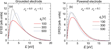
Figure 1. Flux-energy distributions of electrons reaching the electrodes: (a) grounded and (b) powered for different values of  . Discharge conditions: argon, 20 Pa, f = 13.56 MHz,
  V,
V,  ,
,  , and
, and  .
.
Download figure:
Standard image High-resolution imageDual-frequency discharges are investigated at 5 Pa and  V by tuning the phase shift between the driving harmonics, θ, from
  to
to  for various pairs of
  and
and  to study the coupling between the EAE and any surface induced asymmetry due to different electron reflection coefficients. A lower pressure compared to the single-frequency scenario is chosen, since the electrical generation of a DC self-bias via the EAE is strongest at low pressures due its self-amplification under these conditions [65]. Due to the lower pressure a larger electrode gap of L = 2.5 cm is used for the dual-frequency simulations. A systematic pressure and gap variation are beyond the scope of this work.
2.2. Analytical model
In order to analyze and to interpret the simulation results, an analytical model of CCRF discharges is invoked [65]. According to this model, the expression for the DC self-bias voltage,  , can be written in the following form:
where  and
and  is the maximum and the minimum of the applied voltage waveform,
  , respectively. In electropositive low pressure discharges usually the first term dominates and the other terms can be neglected. The two additional terms take into account the residual sheath voltage at the powered and grounded electrode,
  and
and  , that occur at the time of sheath collapse at the respective electrode, and the voltage drop across the plasma bulk at the time of maximum and minimum applied voltage (
 and
and  , respectively). The residual sheath voltages are determined in the following way: First, the position of the sheath edge, s, is determined at each electrode as a function of time within the fundamental RF period according to the following criterion introduced by Brinkmann [66]:

Here, x is the distance from the respective electrode, ni is the ion density, and ne is the electron density. Then, for each electrode the potential drop between the minimum value of s(t) and the electrode at the time of the minimum sheath width is taken to be the residual sheath voltage at that electrode. Note that in a plasma with negligible ion dynamics the time of minimum sheath width coincides with the time of minimum voltage drop across the sheath. If an electric field reversal [67] occurs at an electrode, an inverse sheath [68–71], i.e. a negative space charge, is found at the electrode, when the classical sheath is collapsed. In this case, the above criterion for the determination of the sheath width fails and the width of the (classical) sheath is set to zero. Thus, the field reversal is treated as a bulk phenomenon and is included in the third term of equation (2).
The symmetry parameter, ε, is defined as the ratio of the maximum sheath voltages at both electrodes,  and
and  . For geometrically symmetric discharges:
where  and
and  is the spatially averaged ion density in the sheath at the grounded and powered electrode, while
  and
and  is the maximum positive space charge in the respective sheath [65].
To calculate the self-bias via equation (2), input parameters in terms of the residual sheath voltages, bulk voltages, and symmetry parameter are taken from the simulations. The normalized DC self-bias is defined as  .
.
3. Results
3.1. Single frequency discharges ( )
)

Figure 2(a) shows the time averaged electron density profiles in the discharge gap for different values of the electron reflection coefficient, ρ, in a single frequency discharge. Electrons are reflected from both electrode surfaces with the same probability, i.e.  . The secondary electron emission coefficient, γ, is 0.1 at both electrodes and the neutral gas pressure is 20 Pa. The discharge is excited by a voltage waveform according to equation (1): f = 13.56 MHz,
  V and
V and  V for all ρ. The value of ρ is found to strongly affect the calculated time averaged electron density profiles. The maximum electron density increases by a factor of about 2.2, if ρ is increased from 0 to 0.9 under these conditions (from
  cm−3 to
  cm−3—see figure 2(b)). Figure 2(a) also reveals the impact of the electron reflection on the time averaged widths of the sheaths, which are identical at both electrodes (
 ), since identical reflection probabilities are used. Increasing ρ in the simulations results in a decrease of the sheath widths. This is illustrated in more detail in figure 2(c), where the mean sheath width,
  , is plotted as a function of ρ: a decrease of
  by about 40% is found as ρ is increased from 0 to 0.9.

Figure 2. (a) Time-averaged distributions of the electron density obtained from PIC/MCC simulations for different values of the electron reflection coefficient,  . The powered electrode is located at x = 0 cm. (b) Maximum electron density,
  , and (c) mean sheath width,
  , as a function of
  . Discharge conditions: argon, 20 Pa, f = 13.56 MHz,
  V,
V,  V,
V,  ,
,  .
.
Download figure:
Standard image High-resolution imageThe effect of increasing ρ on the plasma density can be explained based on its effects on the spatio-temporal distribution of the electric field and the ionization rate, shown in figure 3. A remarkable effect that arises at a high reflection probability ( ) is the generation of an electric field reversal at each electrode during sheath collapse (indicated by the dashed rectangles in figure 3(b)). This is caused by the necessity to compensate the positive ion flux by a sufficiently high electron flux to each electrode on time average. For high values of ρ a higher fraction of the incident electrons is reflected back towards the plasma bulk at each electrode. Under such conditions the flux compensation is aided by an electric field reversal generated during sheath collapse, which accelerates electrons towards the electrode [67–71]. Both, bulk electrons drifting towards the electrode and electrons previously reflected at this boundary surface are accelerated towards the electrode by this reversed field. In this way electrons hit the electrode more frequently and more electrons can be absorbed by the electrode even if ρ is high. As electrons are accelerated by the reversed field, additional weak ionization is observed at the electrodes during sheath collapse for
  (dashed rectangles in figure 3(d)) compared to
  (figure 3(c)). The presence of these field reversals increases the residence time and the mean energy of electrons close to the electrodes during sheath collapse. These electrons accumulate at the electrodes and are subsequently accelerated into the plasma bulk by the expanding sheaths. Thus, a high reflection probability also enhances the ionization by energetic electron beams during the sheath expansion phase significantly (see figures 3(c) and (d)). The combination of these mechanisms leads to the increase of the plasma density and to the decrease of the mean sheath widths as a function of ρ observed in figure 2.
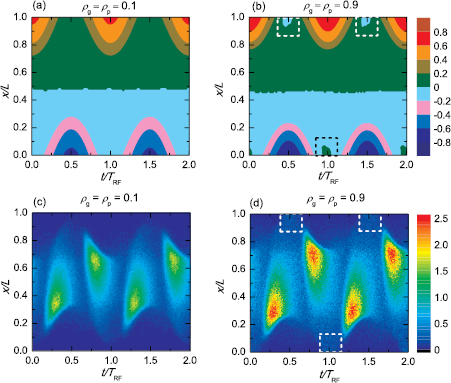
Figure 3. Spatio-temporal distributions of the electric field in units of 105 V m−1 for (a)  and (b)
  , as well as the ionization rates in units of 1021 m−3 s−1 for (c)
  and (d)
  within two consecutive RF periods. The dashed rectangles in plots (b) and (d) indicate the regions, where an electric field reversal develops for high values of ρ. Discharge conditions: argon, 20 Pa, f = 13.56 MHz,
  V,
V,  V,
V,  .
.
Download figure:
Standard image High-resolution imageFigure 4 shows the mean energy,  , and the flux of ions,
  , reaching the electrodes as a function of ρ. The mean energy of the ions increases by about
  at the highest value of
  investigated here compared to the case of
  (figure 4(a)). This can be explained by the influence of the electron reflection on the width of the sheaths: higher plasma densities and shorter sheaths are obtained for high reflection probabilities. Under such conditions, ions undergo fewer collisions inside the sheaths on their way towards the electrodes. Therefore, ions reach the electrodes at higher energies. The increase of
  as a function of ρ, shown in figure 4(b), is the result of the impact of the electron reflection on the plasma density. Increasing ρ causes the plasma density to increase, which finally leads to higher ion fluxes at the electrodes.
  changes by a factor of about 1.6 by tuning ρ from 0 to 0.9.
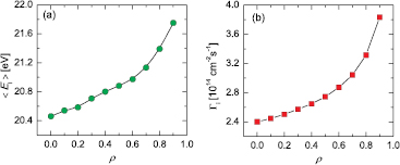
Figure 4. (a) Mean ion energy,  , and (b) ion flux,
  as a function of the electron reflection coefficient, ρ, obtained from PIC/MCC simulations. Discharge conditions: argon, 20 Pa, f = 13.56 MHz,
  V,
V,  V,
V,  ,
,  .
.
Download figure:
Standard image High-resolution image3.2. Single frequency discharges (): a novel surface induced feature of the EAE

In contrast to the previous section, single frequency CCRF plasmas with different electron reflection coefficients at both electrodes ( ) are now investigated under otherwise identical discharge conditions.
  is kept constant at 0.1, while
  is varied between 0.1 and 0.9 at 20 Pa. The secondary electron emission coefficient, γ, is 0.1 at both electrodes.
Figure 5(a) shows the time-averaged electron density profiles for different values of  . Similarly to the situation presented in the previous section, increasing
  leads to an increase of the maximum electron density (see also figure 5(b)). While an increase by a factor of about 2.2 was observed in figure 2, here only an increase by a factor of about 1.4 is found, since only the reflection probability at the grounded electrode is increased, while it was increased at both electrodes in the previous section. The density maximum shifts towards the electrode, where the reflection probability is higher (see figure 5(a)) and the mean sheath width at the grounded electrode becomes smaller compared to the mean sheath width at the powered electrode (see figure 5(c)). Clearly, an asymmetry is induced by using different reflection probabilities at both electrodes.

Figure 5. (a) Time-averaged distributions of the electron density obtained from PIC/MCC simulations for different values of the electron reflection coefficient at the grounded electrode,  (
( is kept constant). The powered electrode is located at x = 0 cm. (b) Maximum electron density,
  , and (c) mean sheath widths at both electrodes,
  and
and  , as a function of
  . Discharge conditions: argon, 20 Pa, f = 13.56 MHz,
  V,
V,  V,
V,  ,
,  .
.
Download figure:
Standard image High-resolution imageFigure 6 shows the spatio-temporal distributions of the electric field for  (a) and
  ,
,  (b), as well as the ionization rates for
  (c) and
  ,
,  (d) within two consecutive RF periods. As discussed in the previous section, an electric field reversal will be generated at a given electrode during sheath collapse, if the local reflection probability is high (see figure 6(b)), in order to accelerate electrons towards this electrode to compensate the positive ion flux in the presence of strong electron reflection. As
  , this happens only at the grounded electrode and not at the powered electrode here. Thus, for
  and
and  the ionization rate at the grounded electrode during sheath collapse is higher compared to that at the powered electrode. Due to the field reversal the residence time of electrons in the region adjacent to the grounded electrode and their mean energy are increased. A few nanoseconds later the sheath expands at the grounded electrode and accelerates these electrons towards the bulk, where they enhance the ionization rate compared to the reference case of
  (see figure 6(c)), too. In this way the plasma density is increased in the entire electrode gap and the ionization rate caused by the expanding sheath at the powered electrode is also increased, since a higher number of more energetic electrons is accelerated compared to the case of
  . The plasma density remains slightly lower at the powered compared to the grounded electrode (see figure 5(a)). Thus, the sheath width is smaller and expands more slowly at the grounded compared to the powered electrode. Therefore, despite the higher local plasma density at the grounded electrode, the ionization rate caused by the expanding sheath is not higher, but similar to the ionization rate caused by the expanding sheath at the powered electrode.
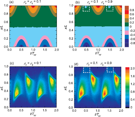
Figure 6. Spatio-temporal distributions of the electric field in units of 105 V m−1 for (a)  and (b)
  ,
,  as well as the ionization rates in units of 1021 m−3 s−1 for (c)
  and (d)
  ,
,  within two consecutive RF periods. The dashed rectangles in plots (b) and (d) indicate the regions, where an electric field reversal is generated. Discharge conditions: argon, 20 Pa, f = 13.56 MHz,
  V,
V,  V,
V,  ,
,  .
.
Download figure:
Standard image High-resolution imageIn an otherwise completely symmetric discharge driven by a sinusoidal voltage waveform, the presence of different electron reflection probabilities at both electrodes results in the formation of a DC self-bias. Figure 7(a) shows that a DC self-bias of up to 15% of the driving voltage amplitude is generated in the case of strongly different electron reflection probabilities at both electrodes under these conditions. The physical origin of this novel surface induced feature of the EAE is different from the generation of a DC self-bias due to the EAE induced by a driving voltage waveform that has different absolute values of its global extrema [65] or different rise and fall times [33, 34, 37].

Figure 7. (a) Absolute value of the normalized DC self-bias,  , as a function of
  obtained from the PIC/MCC simulations (solid line and red circles) and from the analytical model using the first term of equation (2) (dashed line and black squares). Corresponding values of (b) the symmetry parameter,
  , (c) the square of the ratio of the maximum charges in the sheath at the grounded and powered electrode,
  , and the ratio of the spatially averaged ion densities in the sheaths,
  . Discharge conditions: argon, 20 Pa, f = 13.56 MHz,
  V,
V,  V,
V,  ,
,  ,
,  .
.
Download figure:
Standard image High-resolution imageThe formation of the self-bias can be understood by the analytical model introduced in section 2.2. Based on equation (2) the DC self-bias obtained from the simulation can be reproduced by the model by taking the symmetry parameter, the residual sheath voltages at both electrodes, and the voltage drops across the plasma bulk at the times of maximum and minimum applied voltage as input parameters from the simulation. The absolute values of the global extrema of the driving voltage waveform, which are input parameters for the model and the simulation, are identical, since a sinusoidal waveform is used here. The model shows that this novel surface induced feature of the EAE, i.e. the generation of the DC self-bias, is caused by a decrease of the symmetry parameter, ε, as a function of  (see figure 7(b)). According to equation (4) the symmetry parameter is the product of
  and
and  . Both factors are obtained from the simulations, are plotted as a function of
  in figure 7(c), and are found to decrease as a function of the electron reflection probability at the grounded electrode. The decrease of the density factor is caused by the effect of increasing
  on the spatio-temporal ionization dynamics discussed earlier (see figure 6), i.e. there is more ionization at the grounded compared to the powered electrode, if
  .
.  decreases as a function of
  due to the effect of this reflection coefficient on the absolute values of the residual sheath voltages at the grounded electrode, shown in figure 8(a). While the residual sheath voltage at the powered electrode remains almost constant, the absolute value of the residual sheath voltage at the grounded electrode decreases from about 2.6 V for
  to 0 V for
  due to the generation of an electric field reversal at this electrode for high local reflection probabilities and the complete collapse of the sheath (
 for a fraction of the RF period). Thus, for high values of
  the absolute values of the residual sheath voltages are different at both electrodes. If
  at the grounded electrode is lower compared to that at the powered electrode, less residual charge,
  , will be located in the sheath at the grounded electrode during its collapse compared to the residual charge in the sheath at the powered electrode during its collapse,
  . As the total uncompensated charge in the discharge,
  , is approximately constant and purely located inside the sheaths [50], this causes the maximum charge in the powered electrode sheath,
  , to be larger compared to the maximum charge in the grounded electrode sheath,
  . This causes the decrease of
  as a function of
  shown in figure 7(c).

Figure 8. (a) Absolute value of the residual sheath voltages,  , (b) mean ion energy,
  , (c) and ion fluxes,
  at both electrodes as a function of
  at
at  . Discharge conditions: argon, 20 Pa, f = 13.56 MHz,
  V,
V,  V,
V,  ,
,  ,
,  .
.
Download figure:
Standard image High-resolution imageDue to the generation of a DC self-bias as a function of  the mean ion energies will be different at both electrodes, if
  (see figure 8(b)). The ion fluxes at both electrodes increase as a function of
  due to its effect on the spatio-temporal ionization dynamics discussed before (see figure 8(c)).
Figure 9(a) shows the absolute value of the normalized DC self-bias formed via this surface induced feature of the EAE as a function of the driving voltage amplitude,  (
( V), obtained from the simulation and the model using only the first term and all terms of equation (2).
  is found to decrease as a function of
  . The simulation results can be reproduced by the model, only if all three terms of equation (2) are used. Using only the first term is insufficient. Particularly the second term, i.e. the residual sheath voltages, must be taken into account. The model shows that the decrease of
  as a function of
  is caused by an increase of the symmetry parameter (see figure 9(b)). This, in turn, is caused by an increase of
  (see figure 9(c)).

Figure 9. (a)  , (b)
, (b)  , (c)
, (c)  and
and  as a function of
  obtained from the PIC simulations.
  is also obtained from the analytical model using the first term (black squares) and all terms (blue diamonds) of equation (2). Discharge conditions: argon, 20 Pa, f = 13.56 MHz,
  V,
V,  ,
,  , and
, and  .
.
Download figure:
Standard image High-resolution imageThe ratio of the mean ion densities at both electrodes slightly decreases as a function of  , since the ionization rate at the grounded electrode becomes higher compared to the ionization rate at the powered electrode for high driving voltages (see figures 10(c) and (d)). Figures 10(a) and (b) show that this is caused by a stronger electric field reversal at the grounded electrode for high voltage amplitudes. This alone would cause a decrease of ε as a function of
  , but under these conditions the increase of
  dominates. This increase is again caused by the residual sheath voltages: figure 11(a) shows that the residual sheath voltage at the grounded electrode is 0 V independently of
  , due to the presence of a high electron reflection probability at this electrode and the necessity to absorb a sufficient number of electrons to compensate the ion flux in the presence of strong electron reflection. This residual sheath voltage is already at its minimum of 0 V at low voltage amplitudes and cannot decrease further. As the plasma density and the ion flux to both electrodes increase as a function of
  (see figure 11(c)), more electrons must be absorbed at both electrodes during the local sheath collapse to compensate the ion flux. Therefore, at the powered electrode the residual sheath voltage decreases as a function of
  . At the grounded electrode it cannot decrease further. Instead, the field reversal becomes stronger at higher voltage amplitudes. Consequently, the residual sheath voltages at both electrodes and, therefore, the minimum and maximum charges in both sheaths become more similar at high driving voltage amplitudes. Thus,
  increases and, therefore,
  decreases as a function of
  . The mean sheath voltage is higher at the powered electrode compared to the grounded electrode due to the presence of a negative DC self-bias and increases at both sides as a function of the driving voltage amplitude. Thus, the mean ion energy is higher at the powered electrode compared to the grounded electrode and increases as a function of
  .
.
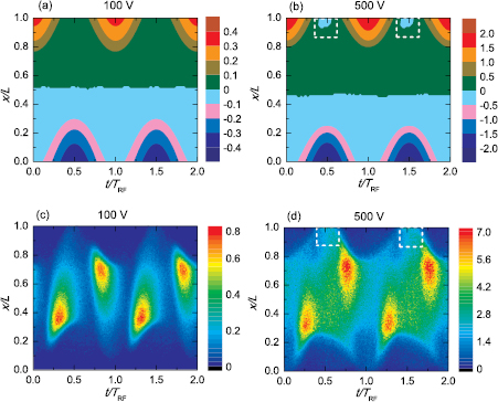
Figure 10. Spatio-temporal distributions of the electric field in units of 105 V m−1 for (a)  V and (b)
  V as well as the ionization rates in units of 1021 m−3 s−1 for (c)
  V and (d)
  V within two consecutive RF periods. The dashed rectangles in plots (b) and (d) indicate the regions, where an electric field reversal is generated. Discharge conditions: argon, 20 Pa, f = 13.56 MHz,
  ,
,  ,
,  V,
V,  .
.
Download figure:
Standard image High-resolution image
Figure 11. (a) Absolute value of the residual sheath voltages,  , (b) mean ion energy,
  , and (c) ion flux,
  , at the powered and grounded electrodes as a function of
  . Discharge conditions: argon, 20 Pa, f = 13.56 MHz,
  V,
V,  ,
,  , and
, and  .
.
Download figure:
Standard image High-resolution image3.3. Dual-frequency discharge ()

In this section, we study the coupling between the classical EAE and the novel surface induced feature of the EAE due to different electron reflection coefficients by investigating discharges driven by a voltage waveform given by equation (1) for  V as a function of the phase, θ, between the driving harmonics. Figure 12(a) shows the normalized DC self-bias,
  , obtained from the simulation as a function of θ for different combinations of
  and
and  . It also includes the model results according to equation (2) for a particular combination of reflection coefficients at both electrodes (
 and
and  , blue dashed line and asterisks). For identical reflection probabilities at both electrodes (
 and
and  ) the DC self-bias is purely generated via the EAE via an amplitude asymmetry of the driving voltage waveform. Similarly to previous investigations on the EAE a self-bias of approximately 25% is found for
  [15, 16, 23]. When
  , the DC self-bias changes compared to the reference case of identical reflection coefficients at both electrodes, i.e. there is a coupling between the EAE and the surface induced feature of the EAE. In this way
  can either be enhanced or reduced by about 25% relative to the value obtained via the EAE alone for all θ, depending on which electrode is chosen to have the higher reflection coefficient. Ultimately, the presence of different electron reflection coefficients leads to a shift of the DC self-bias that is almost the same for all phase shifts, θ. In this sense the coupling between the EAE and the surface induced asymmetry is linear. This is different compared to the non-linear coupling between the EAE and the secondary electron asymmetry effect (SEAE), which can be induced by using electrode materials with different γ-coefficients [52].
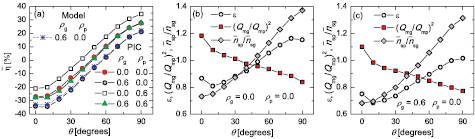
Figure 12. (a) Normalized DC self-bias as a function of  obtained for different combinations of
  and
and  from the PIC/MCC simulations and from the analytical model via equation (2) for
  and
and  . (b) and (c)
  ,
,  and
and  as a function of θ resulting from the simulations for
  ,
,  and
and  ,
,  , respectively. Discharge conditions: argon, 5 Pa,
  ,
,  .
.
Download figure:
Standard image High-resolution imageThe generation of the DC self-bias in the presence of both the EAE and the reflection asymmetry can again be understood by the model: figures 12(b) and (c) show the symmetry parameter,  , and
, and  as a function of θ resulting from the simulations for
  and
and  ,
,  , respectively.
 is found to decrease as a function of θ for
  and
and  ,
,  , but for a given θ this term is always found to be lower for
  . The initial decrease for
  is generally caused by the change of the number of sheath collapses at the grounded electrode within one fundamental RF period from 2 for
  to 1 for
  due to the change of the driving voltage waveform as a function of the phase between the driving frequencies. At the powered electrode the sheath collapses once per fundamental RF period for these phase shifts. This can be observed in figure 13 that shows the spatio-temporal ionization rates as a function of θ under these conditions. If the sheath collapses twice at the grounded electrode, electrons can reach this electrode more easily to compensate the positive ion flux on time average. Thus,
  is relatively high and, consequently,
  is less than
  for
for  , so that
  is larger than unity at this phase shift. For larger phase shifts, the sheath at the grounded electrode collapses only once per fundamental RF period. Consequently,
  must decrease compared to small phase shifts to allow enough electrons to reach this electrode during one sheath collapse to ensure flux compensation. Thus,
  further increases as a function of the phase relative to
  and
and  becomes less than unity. As θ approaches 90°, the sheath at the powered electrode collapses twice within one fundamental RF period. Thus,
  increases and, consequently,
  , and
, and  decrease further. For any given value of θ, the higher electron reflection coefficient at the grounded electrode leads to a lower residual sheath voltage at this electrode compared to the situation of identical reflection coefficients at both electrodes. For a given phase, this increases
  with respect to
  and, thus, leads to lower values of
  compared to the scenario of identical reflection coefficients at both electrodes.

Figure 13. Spatio-temporal plots of the ionization rate in units of 1021 m−3 s−1 for different phase shifts, θ, at  and
and  within one fundamental RF period. Discharge conditions: argon, 5 Pa, f = 13.56 MHz,
  V,
V,  .
.
Download figure:
Standard image High-resolution imageThe ratio of the ion densities at both electrodes increases as a function of θ for  and
and  ,
,  , but for a given θ this term is again found to be lower for
  . At low pressures this term generally increases as a function of θ, since the sheaths are collisionless and a finite DC self-bias leads to higher ion velocities in one compared to the other sheath. Due to flux continuity the ion density must then be lower in one compared to the other sheath. As the polarity of the DC self-bias changes as a function of θ due to the EAE, the ion density ratio is less than unity for small phase shifts (negative self-bias) and higher than unity for large phase shifts (positive self-bias). This is known as the self-amplification of the EAE at low pressures, since it leads to a stronger DC self-bias via the EAE in the presence of collisionless sheaths [65]. For
  and a given value of θ, the ionization rate at the grounded electrode is enhanced relative to the powered electrode. This leads to a shift of
  to lower values. This effect in combination with the shift of
  to lower values in the presence of a higher reflection coefficient at the grounded electrode leads to a shift of the control interval of the DC self-bias towards more negative values. This, in turn, affects
  again due to its effects on the ion acceleration in both sheaths and shifts the density ratio to yet lower values for a given phase shifts, i.e. this effect is self-amplifying.
The combination of these mechanisms explains why the presence of different electron reflection probabilities leads to a shift of the DC self-bias generated via the EAE (see figure 12(a)).
As a consequence of this coupling, using electrodes with different electron reflection coefficients allows to shift the control range of the mean ion energy accessible at both electrodes by tuning the phase to higher/lower energies. The control range itself remains approximately constant (see figures 14(a) and (b)). Meanwhile, the ion flux remains nearly constant as a function of θ for a given choice of electrode materials, but is significantly different for different combinations of reflection coefficients at both electrodes (see figures 14(c) and (d)). Similarly to the EAE without different reflection probabilities, the density remains constant as a function of θ even in the presence of different electron reflection coefficients. This is due to the effect of changing θ on the ionization dynamics shown in figure 13 for  and
and  as an example. Changing the phase from 0° to 90° changes the sheath dynamics in a way that the generation of highly energetic electron beams by the expanding sheath is moved from the bottom powered electrode to the top grounded electrode. However, on time and space average the ionization rate remains approximately the same independent of θ [72].

Figure 14. Mean ion energy,  , and ion flux,
  , as a function of
  obtained for different combinations of
  and
and  from the PIC/MCC simulations for (a, c) the powered and (c, d) the grounded electrode (p = 5 Pa,
  V, 2.5 cm gap).
Download figure:
Standard image High-resolution image
4. Conclusions
The effects of changing the electron sticking/reflection coefficients at the powered and grounded electrodes of capacitively coupled RF plasmas operated in argon at pressures of 5 Pa–20 Pa on plasma parameters were investigated systematically by PIC/MCC simulations. Both single- (13.56 MHz) and dual-frequency discharges driven by 13.56 MHz and 27.12 MHz with fixed, but adjustable phase between both driving harmonics were studied.
High reflection coefficients were found to cause the generation of electric field reversals during sheath collapse. In the presence of strong electron reflection these field reversals accelerate electrons towards the electrode to ensure a compensation of the ion flux to this surface on time average. These field reversals cause additional ionization close to the electrode and increase the residence time of electrons at the electrode as well as their mean energies. A few nanoseconds later the local RF sheath expands and accelerates these electrons into the bulk. In this way the ionization caused by energetic electron beams generated by sheath expansion heating is increased in the presence of strong electron reflection, too. Overall, these effects cause the plasma density and the ion flux to the electrodes to increase as a function of the electron reflection probability at the electrodes. For a given driving voltage amplitude, this causes the sheath widths to decrease. Consequently, the sheaths get less collisional and the mean ion energy at the electrodes increases as a function of the reflection probability.
If different electron reflection probabilities are used at both electrodes in single-frequency plasmas, a discharge asymmetry was found to be induced, i.e. a DC self-bias is generated, that increases as a function of the difference between the reflection coefficients at both electrodes. This surface induced feature of the EAE is explained by the effects of using different reflection probabilities at both electrodes on the spatio-temporal dynamics of the electric field and the ionization rate, as well as the residual sheath voltages at both electrodes during sheath collapse. Based on using two electrodes made of materials with different electron reflection probabilities different mean ion energies can be realized at both electrodes due to the generation of a DC self-bias.
Finally, the coupling between the electrical asymmetry effect (EAE) and this novel surface induced feature of the EAE was studied in dual-frequency plasmas driven by two consecutive harmonics. A linear coupling between both effects was found, i.e. the presence of different electron reflection probabilities at both electrodes leads to a change of the DC self-bias generated via the EAE as a function of the phase between the driving harmonics, but this difference is independent of the phase. Consequently, the control range of the mean ion energy at the electrodes can be shifted to different energies by using electrodes with different reflection probabilities. Meanwhile, the ion flux remains approximately constant as a function of the phase, but its absolute value changes as a function of the electron reflection probabilities. This is different compared to the non-linear coupling between the EAE and the secondary electron asymmetry effect (SEAE), which can be induced by using electrode materials with different γ-coefficients [52].
These findings are highly relevant for surface processing applications, where different electrode materials are typically used. Examples for such scenarios are reactors, where a substrate with strongly different surface coefficients compared to the chamber and counter electrode material is placed on one electrode. Based on the results obtained in this work, i.e. the strong effect of the electron reflection coefficients on plasma parameters, changes of the surface conditions and, thus, surface coefficients might be an important reason for process drifts.
Acknowledgments
This work has been financially supported by the Hungarian Scientific Research Fund, via Grant OTKA K105476.