
Abstract
Multilayer soft lithography has become a powerful tool in analytical chemistry, biochemistry, material and life sciences, and medical research. Complex fluidic micro-circuits require reliable components that integrate easily into microchips. We introduce two novel approaches to master mold fabrication for constructing in-line micro-valves using SU-8. Our fabrication techniques enable robust and versatile integration of many lab-on-a-chip functions including filters, mixers, pumps, stream focusing and cell-culture chambers, with in-line valves. SU-8 created more robust valve master molds than the conventional positive photoresists used in multilayer soft lithography, but maintained the advantages of biocompatibility and rapid prototyping. As an example, we used valve master molds made of SU-8 to fabricate PDMS chips capable of precisely controlling beads or cells in solution.
Export citation and abstract BibTeX RIS

Content from this work may be used under the terms of the Creative Commons Attribution 3.0 licence. Any further distribution of this work must maintain attribution to the author(s) and the title of the work, journal citation and DOI.
1. Introduction
Multilayer soft lithography (MSL) produces in-line microfluidic membrane valves molded around parabolic cross-sectional ridges for precise control of fluid flow. With these valves, externally applied pressure deforms the membrane, which perfectly closes the parabolic-profile channel, unlike square-profile channels that cannot be closed. The control and the flow layers forming the membrane are cast off of photoresist (PR) master molds (masters). Building micro-valves (µvalves) from elastomers like poly(dimethylsiloxane) (PDMS) [1, 2] is well established and has facilitated the development of complex microfluidics much as the transistors have complex electronics. Important on-chip applications of valves include but are not limited to complex integrated circuits [3], cell manipulation [4], digital fluidic logic circuits [5], crystallization [6] and separation [7]. Multilevel features enable additional on-chip functions: cell docking for analysis [8, 9], DNA target detection [10], pillar and weir filters [11], 3D particle focusing [12], and chaotic mixers [13]. MSL is also a flexible and dependable platform for prototyping biocompatible microfluidic devices.
MSL masters typically use patterns of positive tone PR, e.g. SPR-220 or AZ 50 XT, on a substrate to mold µvalves. Under reheating the PR reflows and capillary forces stretch the surface of the PR ridges generating parabolic cross-sectional features. A mold replica cast in a thin layer of PDMS makes a flexible membrane, which operates either as µvalves or as part of micro-pumps, sorters or mixers. Rounded cross-sectional micro-ridges can be generated by exposing SU-8 layers to diffused-light coming through the backside of thin substrates [14], however this approach fails for thick or opaque substrates. Fabrication of rounded, concave profiles in SU-8 was also reported [15] by using timed development and subsequent thermal reflow, but has not been used for fabricating µvalve masters.
Complex experimental designs often require micro-features with different heights and/or complex structures fabricated with grayscale photo-masks [16], electron beam lithography [17], and/or tuned overexposure [18]. In contrast to these more sophisticated fabrication methods, two-step photolithography [19] provides a simple method for constructing multilevel features where the PR spin coating protocol dictates the feature heights, and masters are easily mass produced. Fabricating such masters requires precise 2D alignment of multiple PR layers.
SU-8 is the most common PR for master fabrication because it is chemically and thermally stable after UV polymerization [20]. SU-8 masters allow reliable construction of multi-height features and are robust enough for mass production of PDMS-chips. Both SPR-220 and AZ 50XT failed in our experiments to integrate well with SU-8 in MSL. Both cyclopentanone and 1-methoxy-2-propanol acetate, ingredients in SU-8 master fabrication, are strong solvents for both polymerized and un-polymerized SPR-220 and AZ 50XT. Even with a protective gold nano-coating, the SU-8 lithographic process deforms the SPR-220 µvalve ridges.
Therefore, we introduce two novel methods for fabricating µvalves ridges with rounded profiles and multilevel features entirely out of SU-8 rather than any positive PR such as SPR-220: thin film wings (TFW) and fountain-pen lithography (FPL). These methods integrate multi-level features into durable masters that mold known microfluidic functions.
2. Experimental methods
2.1. Fabrication of master molds
We fabricated the PR µvalve molds on glass using three different lithographic methods. Figure 1 presents major fabrication steps. We cleaned glass substrates (50 × 50 × 3.2 mm3, McMaster Carr) to improve SU-8 adhesion by gently etching them in NH4OH/H2O2/H2O (1:1:1) at 75 °C for 1 h to remove any organic residues, rinsing them with DI-water and methanol, and drying them with N2. We followed the manufacturer's instructions to make layers 3, 15 or 25 µm thick in SU-8 (MicroChem Corp.) and 25 µm thick in SPR-220 (Shipley Company). To make PR-films, we spin coated, soft-baked, UV-irradiated and post-baked the PR layer. To make PR-features we imprinted a 2D pattern onto the PR layer by exposing it to UV through a photo-mask. We removed any excess PR with solvents after post-baking, rinsed solvents from the master, and then dried with N2 gas. Photo-masks were drawn in AutoCAD 3D 2013 (Autodesk, Inc.) and then printed at 40 640 dpi resolution on high neutral density films (Photoplot Store). To improve micro-features adhesion to the glass substrate we covered the glass substrate with a 15 µm SU-8 base layer.
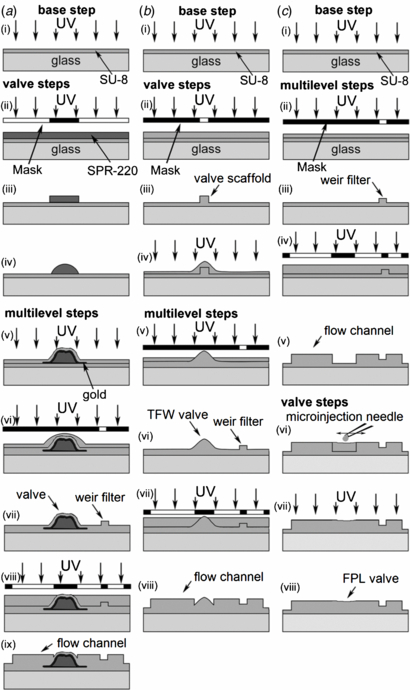
Figure 1. (a) Positive–negative PR method: (i) PR-film: spin coating, soft-bake, UV exposure and post-bake, (ii) PR-feature: spin coating, soft-bake, UV exposure through mask, and post-bake, (iii) develop, (iv) reflow, (v) gold sputtering and PR-film, (vi) PR-feature, (vii) develop, (viii) PR-feature, (ix) develop. (b) TFW method: (i) PR-film, (ii) PR-feature, (iii) develop, (iv) TFW-valve: PR-film, (v) PR-feature, (vi) develop, (vii) PR-feature, (viii) develop. (c) FPL method: (i) PR-film, (ii) PR-feature, (iii) develop (iv) PR-feature, (v) develop, (vi) FPL-valve: draw rounded SU-8 features, (vii) UV exposure, (viii) post-bake.
Download figure:
Standard image High-resolution imageThe positive–negative PR method (figure 1(a)) made SPR-220 µvalve ridges on top of a base layer and protected them from SU-8 solvents with a 50 nm gold film (K675XD, Quorum Emitech) followed by a 3 µm polymerized SU-8 film.
The TFW method (figure 1(b)) exploited the capillarity of SU-8 flowing over rectangular cross-sectional features. As the film is spin coated, its adherence to both vertical and horizontal surfaces rounds all features. The radius of curvature decreases with increasing spinning speed and decreasing in viscosity [21]. To make such rounded µvalve ridges we covered a square-profile SU-8 feature with a 15 µm SU-8 2010 blanket spun at 1500 rpm, soft-baked at 115 °C for 5 min, exposed to 365 nm light at 140 mJ cm−2 and post-baked at 95 °C for 4 min (figure 1(b)). To enhance optical contrast and enable alignment of subsequent PR features, we added 3 µm Al2O3 microspheres to the SU-8 (20 mg:1 mL).
The FPL method (figure 1(c)) followed the principles of a fountain pen; a microinjection needle acted as the nib to draw SU-8 from a reservoir and to deposit it onto the master. The setup consisted of four parts: a dissection microscope (Z45-L, Cambridge Instruments), a 4D micromanipulator (5 µm XYZ resolution, 360° YZ motion, MX10-R, Siskiyou Corporation), a custom syringe holder, and a Hamilton syringe fitted with a microinjection needle. The syringe holder was machined in Delrin® Acetal Resin and connected a micrometer head (2.5 µm/div, 150-832, Mitutoyo) to the piston of a blunt-needle 10 µL Hamilton syringe, allowing us to dispense as little as 0.4 nL/div (disregarding capillary forces and gravity), comparable to the volume of a µvalve.
To make microinjection needles, we thermoformed borosilicate capillary tubes (1 mm OD, 0.5 mm ID) that closely fit the syringe needle OD and clipped its end to make a 10–15 µm diameter port. A micropipette puller (P-87, Sutter Instrument Co.) controlled the taper length and port diameter.
We loaded the syringe with SU-8 and inserted its needle into the microinjection needle. A droplet of epoxy resin bonded the two needles together. After the glue hardened for 30 min, we pushed the SU-8 into the microinjection needle. The air bubble trapped between the walls of the two needles acted as a pressure cushion allowing continuous dispensing of SU-8. We tested three PR formulations: SU-8 2002, 2010 and 2015. We achieved the best results with SU-8 2010. Volatiles in the SU-8 made the droplet form a skin that prevented continuous flow. To correct this issue we kept the microinjection needle in a droplet of cyclopentanone (Sigma-Aldrich Co.) when not writing. We also discarded the first droplets of PR dispensed from the needle before writing.
We manually moved the microinjection needle between the ends of the channel molds that needed to be connected by a µvalve. The volume dispensed was controlled by calibrating the micrometer head to the volume that it forced out. The ridge size depended strongly on the SU-8 formulation and the volume dispensed. More dilute SU-8, such as SU-8 2002, had a larger decrease in volume after soft-baking. SU-8 2002 reliably produced ridges less than 10 µm tall. Valve molds with the wrong shape or size were removed with acetone and redrawn after soft-baking and prior to polymerization. The typical height of FPL ridges varied by ±5 µm for similar volumes of dispensed SU-8, microinjection needle diameters, and SU-8 formulations. For applications requiring more precise valve dimensions, the dispensing process could be automated. The final µvalve mold was soft-baked at 100 °C for 2 min, exposed to 155 mJ cm−2 at 365 nm (Blak-Ray B-100SP UV Lamp, UVP LLC.), and post-baked at 100 °C for 2 min. Each µvalve mold was fully polymerized before the next one was fabricated.
2.2. Chip assembly
We used MSL in PDMS (Sylgard 184, Dow Corning Corp.) to fabricate thin membranes by superposing a flow channel and a control channel. As seen in figure 1 of Melin et al [2], we used two layers of PDMS to create a push-down microfluidic valve. PDMS was cast at 1:10 ratio (curing agent/base elastomer) for all layers. We poured a 5 mm thick control layer over the control master and baked it for 1 h at 100 °C. Holes were punched at inlets for external connections to operate the µvalves. To make a 40 µm flow layer membrane, PDMS was spin coated over the flow master at 1270 rpm and baked for 10 min at 100 °C. Irreversible bonding of PDMS layers and glass relied on surface oxidation to activate the surface of the cross-linked PDMS [22]. Both PDMS layers were oxidized for 30 s in air plasma (400 mTorr) and we used a custom made XY-stage for quick and fine alignment to bond the layers together with the control layer properly superimposed over the valve features so that a pressurized control line would deform and seal the valve. We baked the assembly for 1 h at 85 °C to promote further PDMS bonding and then punched flow layer inlets. Cleaned microscope slides (see above) were plasma treated for 5 min to remove surface hydrocarbons. Then a PDMS assembly and the slide were plasma oxidized for another 45 s and brought into contact binding them to each other irreversibly, thus making a MSL chip.
2.3. Data collection
We measured the PR feature heights and recorded surface profiles with a 20 µg force stylus profiler (Dektak 6M, Veeco Instruments Inc.). Profiler data was exported to Matlab to plot and measure PR-feature dimensions. SU-8 masters were imaged with a scanning electron microscope (SEM, Quanta 600F, FEI Company) and the chip in bright-field with a CMOS camera (1.3 MP B/W, MCE-B013-U, Mightex) connected to an inverted microscope (IMT2, Olympus). To test valve operation we first filled the control channels with degased H2O and used 5–20 psi air pressure to close the µvalve. We then visualized µvalve operation with fluorescein (20 mM in PBS) flowing through the channels under 488 nm light from a 100 W mercury–xenon arc lamp and by tracking flowing 15 µm polystyrene spheres. We used 1–4 psi hydrostatic pressure to maintain liquid flow.
3. Results and discussion
Both of our methods for fully SU-8 masters, TFW and FPL, successfully created PDMS chips capable of precisely controlling bead or cell solutions. TFW, FPL, and positive resist masters were characterized using surface profiling and SEM imaging. The positive PR, SPR-220, failed to integrate well with SU-8 structures because SU-8 dissolves SPR-220. A master mold with gold-coated SPR-220 demonstrated resistance to solvents, but eventually degraded and lost its parabolic shape (figures 2(a), (d), (g)). Therefore, it did not create a full functioning chip because of its lack of structural integrity. Both fully SU-8 masters were tested using a PDMS device consisting of multiple valves, 30 µm channels, and 3 µm weir filters.

Figure 2. Lateral surface profiles of rounded micro-features fabricated with: (a) positive–negative PR, (b) TFW, and (c) FPL. Longitudinal surface profiles of rounded micro-features fabricated with: (d) positive–negative PR, (e) TFW, and (f) FPL. Scanning electron micrographs of master molds fabricated with: (g) positive–negative PR, (h) TFW, and (i) FPL. Image (g) shows the SPR220 µvalve ridge only (no channel ridge or weir filter). Images (h) and (i) have the same scale.
Download figure:
Standard image High-resolution imageDevelopments in single-cell analysis take great advantage of microfluidics' figures-of-merit: high control of flow velocity, biomolecular interactions, reagent volumes and concentration gradient reproducibility. Live cells are delicate and their behavior is readily affected by interactions with the environment. Precise controls over the cellular microenvironment, however, should permit the direction of a number of single cell activities. These range from the priming of immune cells for effector function to the programming of stem cells for regeneration, to the stimulation of tumor initiating cells for single cell transcriptomics. To take advantage of such microfluidic functions, one must easily and robustly combine diverse micro-features fabricated through multi-layer photolithography with µvalves on the same master. After all, the master fabrication is the most time consuming and delicate operation in microfluidic chip fabrication.
Many µvalve designs have been implemented over the years [23]. Our experiments require that weir filters and remotely actuated µvalves are in close proximity (figure 3), so we adopted the MSL µvalve design. [1] Their on-chip integration made us face new challenges; two major constraints led to the development of master fabrication methods of µvalves and multilevel features in SU-8.
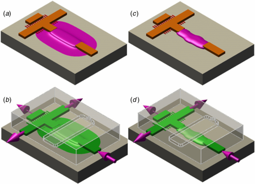
Figure 3. (a) and (b) 3D rendering of SU-8 flow masters with µvalve ridges (pink), flow ridges (orange) and weir filter (red) fabricated with (a) TFW and (b) FPL. (c) and (d) 3D rendering of a PDMS chip showing the superposition of a control channel (dotted line) and a flow channel (green) cast from masters fabricated with (c) TFW and (d) FPL. Arrows show the direction of flow. See figure 4 for a top view of the both types of valves in operation.
Download figure:
Standard image High-resolution imageWhen the master was fabricated in SPR-220, the weir filters were unreliable. When we fabricated the filters first, their size arbitrarily changed after the addition of a new PR layer. When we fabricated the filters last, their shape deformed as the 3 µm PR layer draped down from the 25 µm tall channels. Fabricating the filters in SU-8 solved these because after polymerization SU-8 is chemically and thermally stable, and mechanically robust, allowing high contrast high precise designs. [24] However, when we fabricated the master in SU-8 using standard techniques, the µvalves would not close as all SU-8 channels have rectangular profiles.
Our attempts to build multilevel SU-8 features and rounded-profile SPR-220 µvalves on the same master mold also failed. When we built SU-8 features first, the SPR-220 residue clogged the weir filters rendering the master unusable. Extended developing steps unclogged the filters, but etched the µvalves as well. When we built the SPR-220 µvalves first, the subsequent SU-8 layers dissolved them. The SU-8 2000 series uses cyclopentanone as a diluent and uses 1-methoxy-2-propanol acetate, ethyl lactate and diacetone alcohol as developer ingredients. The main diluent in AZ 50XT is 1-methoxy-2-propanol acetate, while the main diluent in SPR-220 is ethyl lactate. Cyclopentanone is a strong solvent for all of the above PRs as they are all cresol novolac resin based. Since the positive PRs never harden, they remain susceptible to solvents throughout all lithography steps. Physical isolation with 50 nm sputtered gold layer solved the chemical incompatibility, but did not insulate the PRs (figures 1(a), 2(a), (d), (g)). The temperature cycles used to deposit other SU-8 layers induced chaotic reflows of SPR-220, generating sharp wrinkles. The loss of a smooth parabolic profile led to defective µvalves when cast in PDMS, which did not close. Figure 2(g) presents an isolated µvalve ridge of SPR-220 to shows these temperature induced deformations (the channel and weir filter were not fabricated on this flow master since attempts to add these features degraded the SPR-220 ridge).
3.1. SU-8 micro-valve master molds
TFW and FPL successfully created robust masters with µvalve ridges adjacent to other SU-8 micro-features. We tested the µvalves in MSL PDMS devices made with one flow layer which included a µvalve, a 25 µm T-channel and a 3 µm weir filter (figure 3), and one control layer which allowed us to actuate the PDMS membrane to open/close the µvalve. Figure 3 shows how the masters' components of figure 2 relate to a working PDMS chip (figure 4).

Figure 4. Epi-fluorescence images of fluorescein-filled PDMS chips with a closed (a) TFW µvalve and (b) FPL µvalve. Bright-field images of polystyrene spheres flowing through PDMS chips with an open (c) TFW µvalve and (d) FPL µvalve. Arrows point to microspheres flowing at ≈1.2 mm s−1. All images have the same scale.
Download figure:
Standard image High-resolution image
The two methods produced distinct rounding patterns. The TFW µvalves had wide, shallow-gradient wings (figures 2(b), (e), (h)), which worked perfectly with filtered reagents or live cells, but not with hard particles (e.g. 15 µm polystyrene spheres), since particles were trapped under the wings during operation. PR surface tension forces rounded the FPL µvalves. They have near-parabolic profile with dimensions similar to those of the flow channels. Figure 2 shows the large differences in aspect ratios (height-to-width) and the SEM images the overall shape. TFW µvalve aspect ratios varied from sample-to-sample from 1:20 (figure 2(c)) to 1:40 (figure 2(b)) and were dependent on the pressure applied to PDMS when closing the chip with a slide. FPL µvalves had more consistent aspect ratios, ≈1:7 and operational µvalves as narrow as 15 µm were easily drawn (data not shown).
3.2. PDMS chip test
As a test, we constructed a channel crossing with one valved input and three outputs, where the middle output includes a weir-filter. Contrast analysis of epi-fluorescence images showed that closed µvalves completely stopped the fluid flow (dark band across the input channel in figures 4(a) and (b)). Valve closing pressure depended on the dimensions of the valve and the fluid pressure in the flow line. Higher flow line pressures required higher control line pressures to completely seal the valve. 15 µm bead solutions were used to show that the valves could properly stop beads with a quick response time and that the weir filter would allow fluid flow but not beads (figure 4). During later experiments, both types of µvalves closed without PDMS layer delamination and required actuating pressures similar to those chips cast with reflowed SPR-220 masters. [25] TFW and FPL worked on opaque substrates unlike Futai et al [14] and did not require any additional micromolding steps like Kim et al [15].
4. Conclusions
These two new SU-8 only methods for fabricating µvalve molds are simple, flexible and robust, and integrate with multilevel micro-features better than conventional positive PR methods. We demonstrated their on-chip integration with multilevel features like deep channel and shallow weir filters. The fabrication methods allow µvalves with different aspect ratios. Tests show a complete stop of the flow. These fabrication techniques should find use in applications that require multiple microfluidic functions and µvalves colocation, e.g. to chemically expose selected regions on chip, isolate cells for analysis, or direct flow precisely to existing multilevel features. The robustness of SU-8 allows for mass production replica molding from a single master mold.
Acknowledgment
We acknowledge support from NSF/IDBR grant DBI-1152030.