
Abstract
This paper describes the development of a novel technology that can form a dense and complex pattern on a polymer tube without thermal damage. We have developed an etching mask and equipment capable of processing the tubular material. We named this technology cylindrical RIE (reactive ion etching). In order to evaluate the fundamental processing characteristics of this technology, etching rate, side etching ratio and etching uniformities along the tube axis and circumferential directions are evaluated. As a result, a vertical wall caused by anisotropic etching could be observed, and the average etching rate was 1.0 µm min−1 and the average side etching ratio was 0.027. The maximum differences between etching rate along the axis and circumferential directions were 0.25 and 0.12 µm min−1, respectively. The cross-section of the etched through-groove (slit) processed in a PP (polypropylene) tube having wall thickness of 200 µm was evaluated. By the bowing phenomenon, pattern width decreased most at the middle of the thickness of the tube wall, and average width errors at the middle of the thickness was 22.4 µm. To demonstrate the usefulness of the cylindrical RIE, a stent made of PP tube was fabricated. It was possible to fabricate a stent with an outer diameter of 4.4 mm, length of 19 mm, main strut width of 300 µm, and connecting strut width of 80 µm.
Export citation and abstract BibTeX RIS
1. Introduction
Minimally invasive medical care enabling easy postoperative rehabilitation is required for the advent of an aging society, and medical treatment using a catheter or a stent, called percutaneous coronary intervention (PCI), is often performed. However, stent thrombosis and restenosis of a blood vessel caused by chronic inflammation is a concern because metal stents such as the bare metal stent (BMS) and the drug-eluting stent (DES) remain permanently in the body. Therefore, stents made of biodegradable polymer as an alternative to the metal ones have been attracting attention, and coronary stents eluting an immunosuppressant with a strut made of PLA [1] and a biodegradable polymeric stent made of a mixed material of P4HB and PLLA for improving elongation at breaks [2] have also been developed.
Laser processing is used for fabricating stents, and the altered layer by melting has been confirmed at the edge portion of the struts of the stent [3]. It has been found that formation of the altered layer greatly reduces the fracture strain [4]. Further, laser processing is a single-stroke patterning process and takes a long time to fabricate dense and complex patterns. In addition, a tubular scaffold for cultivating cells has been fabricated by knitting fibers of a biodegradable polymer and used for autologous transplantation performed in regenerative medicine [5].
However, the machining methods described above are not suitable for the formation of dense and complex patterns. Therefore, for making high performance medical instruments with dense and complex patterns, new batch microfabrication technology that can process complex fine patterns at a low temperature without thermal damage is necessary. On the other hand, in MEMS technology, RIE (reactive ion etching) is known as a technique for anisotropic micromachining of Si [6], polyimide [7], polymethylmethacrylate (PMMA) [8], fluoropolymer [9, 10], etc. For organic materials, oxygen is ordinarily used as an etching gas, and oxygen radials and ions react with organic materials. Finally, organic materials are removed as H2O, CO, CO2, etc [11].
In this study, we attempted to develop novel RIE technology capable of dealing with a cylindrical surface. RIE equipment previously used for deep etching of plane samples was modified, and the etching characteristics were evaluated with the developed equipment. In addition, an etching mask suitable for this cylindrical surface process was also developed [12]. The polymer stent as an application to the medical field was fabricated to demonstrate its usefulness. Hereinafter this processing technology is referred to as a cylindrical RIE.
2. Cylindrical RIE technology
A schematic diagram of the cylindrical RIE equipment developed in this study is shown in figure 1. The main feature of this equipment is that it comprises a columnar electrode for insertion into the tubular sample, unlike general RIE equipment. The plasma is generated by RF power applied to upper plasma generation electrodes. Subsequently, the ions in the plasma perpendicularly enter the surface of the columnar electrode by a self-bias negative voltage on the columnar electrode generated by RF power supplied to the sample stage. The etching process of the tubular sample is shown in figure 2. First, the tubular sample (cylindrical work) to be processed is attached to the columnar electrode coated with silicone high vacuum grease (figure 2(a)). Subsequently, the flexible stencil mask is pasted on the outside of the tubular sample (figure 2(b)). Ions in the plasma enter perpendicularly toward the columnar electrodes, which pass through the openings of the stencil mask, and the tubular sample is etched (figure 2(c)). Finally, the tubular sample is removed from the columnar electrode, and the stencil mask is also removed (figure 2(d)).

Figure 1. Schematic of developed cylindrical RIE equipment.
Download figure:
Standard image High-resolution image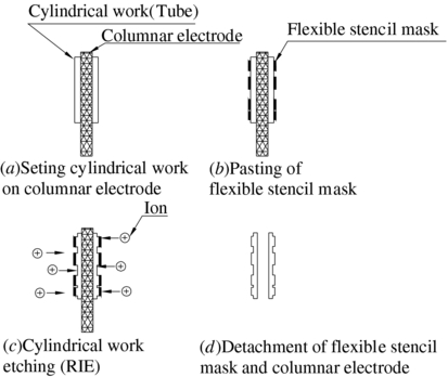
Figure 2. Etching process.
Download figure:
Standard image High-resolution imageThe columnar electrode cooling system developed in this study is shown in figure 3. A structure in which cooling water passes through the interior of the columnar electrode is adopted. Thereby, uniform cooling is enabled and the process can be performed uniformly without a temperature difference between the upper and lower parts of the columnar electrode. In this equipment, the columnar electrode is eccentric relative to the center of the sample stage because it is assumed that many columnar electrodes will be installed in the future for batch processing of many samples at once.

Figure 3. Cooling system.
Download figure:
Standard image High-resolution image3. Evaluation of the etching characteristics
3.1. Method
In order to clarify the etching characteristics of the developed cylindrical RIE, etching rate, side etching ratio and their uniformities were evaluated. The sample was a tube made of PP (polypropylene), and oxygen was used as the etching gas in this experiment. The PP tube had length of 35 mm, average outer diameter of 4.4 mm, and average thickness of 200 µm.
First, a flexible stencil mask to transfer the pattern to the PP tube was fabricated [12]. As the stencil mask is placed and pasted around the cylindrical surface of the sample, it is necessary to have flexibility. Therefore, polyimide film (Kapton 100 H, thickness: t = 25 µm, Du Pont) was used as the stencil mask material. It was etched thoroughly by oxygen RIE with an Al mask, and the entire surface was coated with Al in order to provide the resistance for oxygen plasma. Details of the stencil mask pattern in this experiment are shown in figure 4. Numbers indicated at the top of figure 4 show the observed and measured positions in the circumferential direction. In the axial direction, observation and measurement is carried out at three parts: upper, middle, and lower. Several types of L&S (line and space) patterns are provided in the stencil mask and the patterns to be measured at the upper, middle and lower parts are 40 µm L&S pattern. The technique used to paste the stencil mask onto a tube is schematically shown in figure 5. First, a sacrificial layer of resist is coated on a glass substrate, and 8 µm thick adhesive is also coated thereon (figure 5(a), (b)). Subsequently, the stencil mask is pasted onto the substrate, and the adhesive in the opening of the stencil mask is removed by oxygen RIE (figure 5(c), (d)). Finally, the sacrificial layer is removed to peel off the stencil mask, and the stencil mask is pasted on the tubular sample with the columnar electrode by rolling (figure 5(e), (f)). The flexible stencil mask can be used several times until the Al on the surface is removed by sputtering during the RIE process. After the cylindrical RIE process, the flexible stencil mask removed from the sample is cleaned and processed again as mentioned above for pasting.

Figure 4. Pattern of a flexible stencil mask.
Download figure:
Standard image High-resolution image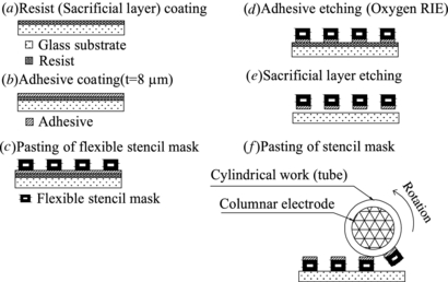
Figure 5. Method of pasting flexible stencil mask to tube.
Download figure:
Standard image High-resolution imageEtching conditions for the evaluation are shown in table 1. For evaluation of etching characteristics, an etched PP tube is cut into round slices in the direction perpendicular to the lines at the three locations, which are the center of the upper, middle and lower parts as shown in figure 6. The dimensions of the cross-section of etched grooves are measured by using an optical microscope at 11 positions in circumferential direction, as shown in figure 4, at each location.
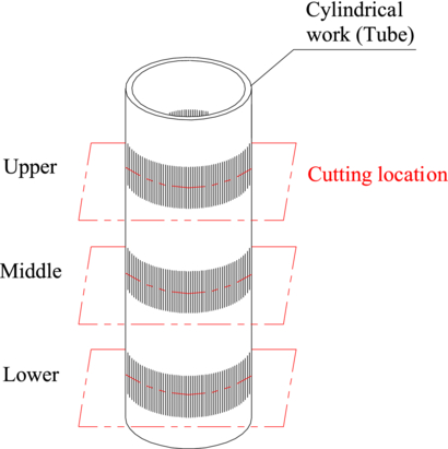
Figure 6. Cutting location for observation and measurement.
Download figure:
Standard image High-resolution imageTable 1. RIE condition for evaluating etching characteristics.
| Condition | Value |
|---|---|
| RF power for plasma generation (W) | 200 |
| Self bias voltage of columnar electrode (V) | −300 |
| Flow rate of oxygen (SCCM) | 15 |
| Pressure in chamber (mTorr) | 30 |
| Temperature of stage (°C) | 2 |
| Flow rate of coolant (l min−1) | 1 |
| Etching time (min) | 90 |
3.2. Results
Optical microphotographs of the cross-section of the etched groove at the upper, middle, and lower part are shown in figure 7. Progress of etching is in the radial direction of the columnar electrode at all of observation points of upper, middle and lower. In addition, the vertical sidewalls are substantially formed, and it was confirmed that it could perform anisotropic etching of PP tube. Similar results also have been obtained previously in a PLA tube [12].
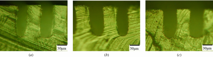
Figure 7. Microphotograph of cross-section of etched grooves with 40 µm L&S pattern of: (a) upper part, (b) middle part, and (c) lower part.
Download figure:
Standard image High-resolution imageThe top view of part of a sample stage is shown in figure 8. Numbers indicated around the columnar electrode are measured position number, which is arranged in the stencil mask shown in figure 4. The circumferential distribution map of the etching rate and the side etching ratio are shown in figure 9. In the distribution of the circumferential direction, the etching rate decreases at the coolant pipe side (measured position 5, 6 and 7) where there are structures for the coolant passage, and the etching rate increases at the plasma generation electrode side (measured position 1, 2, 10 and 11), namely, a difference in the circumferential direction was observed. It is considered that the etching rate decreased at the coolant pipe side because evacuation of the reaction products and supply of the etching gas were inhibited by the coolant passage structure. In addition, it is considered that there is high density plasma on the plasma generation electrode side, and, therefore, a lot of ions enter the sample. Finally, it is considered that a lot of ions coming into the position 1 and 2 caused a large difference in circumference.

Figure 8. Relation of the stage and the measured position number.
Download figure:
Standard image High-resolution image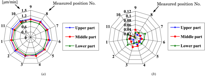
Figure 9. Etching property: (a) etching rate and (b) side etching ratio.
Download figure:
Standard image High-resolution imageThe mean values and standard deviation (SD) of the etching rate at each cutting location are summarized in table 2. The mean etching rate was 1.0 µm min−1. The mean values and SDs of the side etching ratio (side etching width/etching depth) are also summarized in table 2. The mean side etching ratio was 0.027. The tendency for the etching rate to decrease from the upper to the lower part was observed. On the other hand, the side etching ratio had the tendency to increase from the upper to the lower part. The maximum differences of etching rate along axis and circumferential directions were 0.25 and 0.12 µm min−1, respectively. The maximum differences of side etching ratio along axis and circumferential directions were 0.048 and 0.042, respectively.
Table 2. Measurement result of the etching rate and side etching ratio.
| Cutting location | Etching rate (µm min−1) | Side etching ratio | |
|---|---|---|---|
| Upper | Mean | 1.1 | 0.022 |
| SD | 0.039 | 0.0067 | |
| Middle | Mean | 1.0 | 0.027 |
| SD | 0.034 | 0.0093 | |
| Lower | Mean | 0.94 | 0.032 |
| SD | 0.041 | 0.013 |
3.3. Discussion
The etching rate of about 1 µm min−1 in this paper is reasonable for dry process [6–8,10], but it is slower than that of other machining methods. In order to increase the etch rate without increasing the side etching ratio, the density of oxygen ions around the columnar electrode has to be increased. For this purpose, a new plasma source, such as inductively coupled plasma, electron cyclotron resonance and so on, could be used for generating a high density of ions, and a higher etching rate can be expected [11]. On the other hand, the distance between sample and plasma or the distribution of plasma is important. It is found that the distribution of plasma influences the etching rate and the side etching ratio in figure 9. If the distance between the sample and plasma becomes small, the etching rate becomes high [12]. It means that the etching characteristics are strongly influenced by the distance to or the distribution of plasma, that is, the uniformity of the etching characteristics may be deteriorated by them, especially in the case of using the new plasma source because of high plasma density. The equipment used in this study is basically designed for use with plane samples, so it is not appropriate for tubular samples. In the future, it is necessary to investigate the etching characteristics and phenomenon further, and to design RIE equipment for tubular samples from the viewpoint of the density and uniformity of the plasma and the gas flow.
In the process described in this paper, the patterning resolution is mainly restricted by the resolution of the pattern on the flexible stencil mask. The stencil mask is required to have enough strength and stiffness to be handled and keep shape during the process. So the stencil mask has to be quite thick and that restricts the use of very fine patterns. Therefore, another masking method is needed for making from nm to several µm scale patterns. Microcontact printing (µCP) technology [13] may be applicable for solving this problem.
4. Penetration etching of a PP tube
4.1. Method
In order to clarify the possibilities for application to the fabrication of medical devices, the cross-sectional shape of through-groove etched by the cylindrical RIE was evaluated. The stencil mask and PP tube used in the penetration etching are the same as those in experiments described above. The processing conditions used in the etching are shown in table 1. However, etching time was 264 min including over etching time for compensating the ununiformity of etch rate and tube thickness of 200 µm. Evaluation of the etching characteristics is done by measuring the amount of side etching of 40 µm L&S pattern at each upper, middle and lower part, as shown in figure 4.
4.2. Results
An SEM microphotograph of the tube surface after the penetration etching is shown in figure 10. It is confirmed that the penetration etching can be done without significant pattern damage. An SEM microphotograph of the cross-section of the etched grooves (slits) is shown in figure 11. A shape abnormality called bowing that was a feature of the RIE processing was confirmed on the etched groove wall. The dimension of the cross-sectional shape was quantitatively evaluated as follows. First, a theoretical shape of cross-section, as shown in figure 12, was considered. Figure 12 shows a cross-sectional shape of ideal etched groove without side etching if the ions are incident toward the center of the columnar electrode. It should be considered that the difference of the incident direction of the ions causes a reduction in the pattern width of the inside of the tube as compared to that of the outside of the tube. Secondarily, the measured pattern width was compared with the theoretical pattern width. An optical micrograph of the cross-section of the etched grooves (slits) of the PP tube is shown in figure 13. The pattern width at three positions, which were outside and inside of the tube and at the middle of the thickness, were measured, as shown in figure 13, on each cross-section at eight positions in the upper part, at 10 positions in the middle part, and at 11 positions in the lower part, respectively. The differences of the measured pattern width from the theoretical pattern width are summarized in table 3. At the middle of the thickness in all measured positions, the measured pattern width decreases a great deal and the difference between the measured and theoretical pattern width is largest. The mean difference was 22.4 µm. The maximum difference of 29.8 µm was locally observed in the middle part of the tube. It is, therefore, found that the mean machining error of a pattern of 40 µm in width becomes 56%. In medical field, the metal stent has a strut from 59 to 115 µm wide [14], and the stent using a biodegradable polymer has a strut from about 150 to 500 µm wide [1, 2, 15]. The machining error of the cylindrical RIE technology is sufficiently smaller than their strut width, and, therefore, it is considered that cylindrical RIE technology can be applied to fabricate a cylindrical medical device such as a stent.
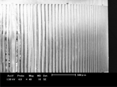
Figure 10. SEM image of the outer surface of etched PP tube.
Download figure:
Standard image High-resolution image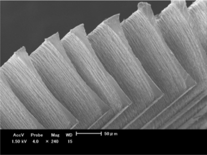
Figure 11. SEM image of the cross-section of etched PP tube.
Download figure:
Standard image High-resolution image
Figure 12. Theoretical configuration of cross-section.
Download figure:
Standard image High-resolution image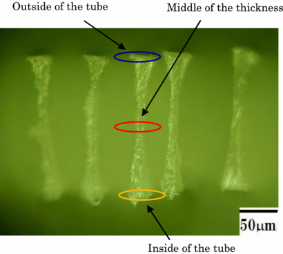
Figure 13. Measurement position of the cross-section.
Download figure:
Standard image High-resolution imageTable 3. Difference of the measured pattern width from the theoretical pattern width of PP tube with 40 µm L&S pattern.
| Measurement position | ||||
|---|---|---|---|---|
| Cutting location | Outside | Middle | Inside | |
| Upper part | Mean | −6.08 µm | −20.3 µm | 0.98 µm |
| SD | 5.04 µm | 6.34 µm | 2.87 µm | |
| Middle part | Mean | −9.04 µm | −25.9 µm | −4.89 µm |
| SD | 5.73 µm | 2.52 µm | 4.35 µm | |
| Lower part | Mean | −7.29 µm | −20.9 µm | −3.29 µm |
| SD | 5.43 µm | 3.48 µm | 7.89 µm | |
5. Trial fabrication of polymer stent
5.1. Method
To demonstrate the usefulness of the cylindrical RIE technology, a prototype stent made from a PP tube was fabricated. The PP tube has the same dimensions described above, and the etching is performed under the same conditions in table 1. However, the etching time was 306 min, which was needed according to the observation during the experiment. The pattern of the stencil mask used in fabrication is shown in figure 14. References [15] and [2] were used for pattern and size references, respectively. The length of the stent is 19 mm. The widths of the main strut part and the connecting strut part are 300 and 80 µm, respectively. In addition, superposition of 600 µm at both ends of the stencil mask was provided. The superposition can connect patterns and keep the stent shape even if an error occurs during pasting of the stencil mask.

Figure 14. Pattern of flexible stencil mask for stent.
Download figure:
Standard image High-resolution image5.2. Results
A photograph of a fabricated stent is shown in figure 15. It is found to be possible to fabricate a stent with a PP tube. SEM microphotographs of two parts are shown in figure 16. It is confirmed to be possible to form the stent pattern, especially the connecting strut that is the narrowest pattern, without corruption. Therefore, the proposed cylindrical RIE technology is useful for the fabrication of polymeric stents.

Figure 15. Photograph of fabricated stent.
Download figure:
Standard image High-resolution image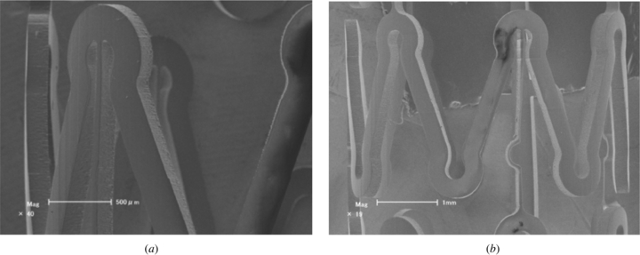
Figure 16. SEM image of fabricated stent: (a) magnification of part A and (b) magnification of part B of figure 15.
Download figure:
Standard image High-resolution image
6. Conclusions
A cylindrical RIE technology has been proposed, and related tools including a flexible stencil mask and a cylindrical RIE equipment have also been developed.
The etching characteristics of the cylindrical RIE technology were evaluated. A PP tube was used as a material and oxygen gas was used as an etching gas. As a result, it was seen that the etching direction was in the direction to the center of the columnar electrode by observing the cross-section of etched grooves, and a substatial vertical sidewall was formed. Thereby it was confirmed that the cylindrical RIE also has the feature of anisotropy.
The experimental results under the etching conditions of the plasma generation power of 200 W and the self bias voltage of −300 V are as follows. The side etching ratios were 0.022, 0.027 and 0.032 in the upper part, the middle part and the lower part, respectively. The mean etching rate and the mean side etching ratio were 1.0 µm min−1 and 0.027, respectively. The maximum differences of etching rate along axis and circumferential directions were 0.25 and 0.12 µm min−1, respectively.
The cross-sectional shape of the etched slit was evaluated by using a PP tube with an outer diameter of 4.4 mm and wall thickness of 200 µm. Pattern width greatly decreased at the middle of the thickness of tube wall because of an abnormal shape called bowing. In the case of the 40 µm L&S pattern, at the middle of the thickness of tube wall, mean width errors were 20.3 µm in the upper part of the tube, 25.9 µm in the middle part of the tube, and 20.9 µm in the lower part of the tube, and then, whole mean width error was 22.4 µm. Maximum width error of 29.8 µm was observed locally in the middle part.
By using cylindrical RIE technology, the trial stent with outer diameter of 4.4 mm, length of 19 mm and wall thickness of 200 µm was made of PP tube. As a result, it was possible to fabricate a stent with a main strut of 300 µm in width and a connecting strut of 80 µm in width.
Acknowledgments
This study was partially supported by a Science and Technology Research Grant from the Suzuki Foundation. We would like to thank Seiwa Co., Ltd, Japan, for providing the PP tubes. We would also like to thank Choshu Industry Co., Ltd, Japan, and the Institute of Bio-Medical and Welfare Engineering, Japan, for technical and financial support, respectively.