
Abstract
An imaging system capable of detecting alumina on turbine blades by acquiring LED-induced fluorescence images has been developed. Acquiring fluorescence images at adjacent spectral bands allows the system to distinguish alumina from fluorescent surface contaminants. Repair and overhaul processes require that alumina is entirely removed from the blades by grit blasting and chemical stripping. The capability of the system to detect alumina has been investigated with two series of turbine blades provided by Rolls-Royce plc. The results illustrate that the system provides a superior inspection method to visual assessment when ascertaining whether alumina is present on turbine blades during repair and overhaul processes.
Export citation and abstract BibTeX RIS

Content from this work may be used under the terms of the Creative Commons Attribution 3.0 licence. Any further distribution of this work must maintain attribution to the author(s) and the title of the work, journal citation and DOI.
This article was made open access on 23 Decmeber 2014
1. Introduction
Turbine engines are periodically sent to repair and overhaul facilities where the engines are disassembled and the components individually inspected for oxidation, corrosion and mechanical wear [1]. High-value components such as turbine blades are repaired and recycled wherever possible; this is a cost effective and sustainable approach to engine overhaul. A range of non-destructive tests (NDT) are carried out to provide a comprehensive inspection at the start of this process to determine whether a part is suitable for repair. NDT methods typically provide data which is not available to the naked eye; however, visual inspections are still used in certain stages of the repair and overhaul process. Visual inspections are inherently subjective since they rely upon the skill and experience of each individual inspector. The potential consequences of human error in sentencing critical engine components are obvious and in order to further reduce the risks of this occurring it is desirable to reduce the possibility of error at all stages of production, repair and overhaul processes. The subjective nature of visual inspections is unsatisfactory and for the present work motivated the development of an imaging system to provide a superior, objective method of performing certain component inspections.
Light emitting diode (LED)-induced-fluorescence imaging is an analytical method in the biological [2] and medical sciences [3]. LEDs excite fluorescence in organic samples or fluorescent stains bonded to specific chemical groups in the analyte. This provides a means of observing biological processes by imaging the fluorescence with a charge-coupled device (CCD). Here, we have applied this method to the analysis of turbine blades. Turbine blades develop a photoluminescent oxide on their surface during service in a turbine engine [4], removing the necessity for surface preparations such as fluorescent staining. The high temperatures in the turbine engine during operation oxidize the blade's protective nickel–aluminide diffusion coating to form alpha-alumina ( ) [5].
  is the thermodynamically-stable phase of aluminium oxide which fluoresces in the red band of the spectrum. The fluorescence occurs due to trace amounts of chromium ions (Cr3 +) incorporated into the crystal lattice. The photoluminescent process is known as ruby fluorescence which was extensively investigated in the 1950s leading to the invention of the ruby laser [6].
 consists of a trigonally distorted octahedra of oxygen ions (O2−) around aluminium ions (Al3+) and ionically substituted chromium ions (Cr3+) occupying Al3+ positions in the lattice [7]. The Cr3 + ions have a strong optical absorption band in the green region of the visible spectrum. Figure 1 shows a simplified diagram of the energy-levels in Cr3 + ions in
  relevant to the ruby fluorescence process. Absorped photons in the green band excite electrons from the ground state,
  , to the
  state. The electrons non-radiatively transition to the metastable
  state which is split into the
  and
and  states due to zero-field splitting and spin-orbit coupling [8]. Equations (1a) and (1b) show the spontaneous decay of electrons to the ground state from the
  and
and  states producing the R1 and R2 spectral lines characteristic of ruby fluorescence:


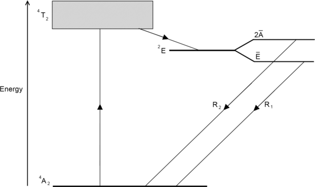
Figure 1. Simplified energy-level diagram of Cr3 + in  showing the ruby fluorescence processes.
Download figure:
Standard image High-resolution imageThe repair and overhaul process requires that turbine blades are entirely stripped of their oxidized diffusion coating before a new coating can be deposited [9]. This is achieved by alumina-grit blasting and immersive chemical stripping in hot sulphamic and nitric acid [10]. The effectiveness of the stripping process is currently determined by subjective visual assessments. An imaging system has been developed to detect residual alumina on turbine blades by exciting ruby fluorescence in  . This paper presents the development of the imaging system and the results produced from imaging two example series of Rolls-Royce plc turbine blades.
2. Imaging system
Figure 2 shows a diagram of the imaging system. The system consist of an Atik 314E monochromatic camera (Artemis CCD Ltd) with an ICX205AL ExView 1392 × 1040 CCD (Sony Corporation). The camera can be set to acquire images from a minimum exposure time of 1 ms up to a user-defined maximum with in-house-developed software. The camera is equipped with a Computar 12 mm 1:1.2 TV lens (CBC Group). The lens is mounted on a Cage Cube (Thorlabs Inc) containing a VersaChrome® bandpass filter (Semrock Inc). The bandpass filter can be tuned by changing the angle of incidence from 697 nm ± 13 nm at 0° to 618.5 nm ± 13 nm at 60°. The Cage Cube is mounted on a light-tight enclosure constructed from aluminium structural frame and black aluminium sheet.
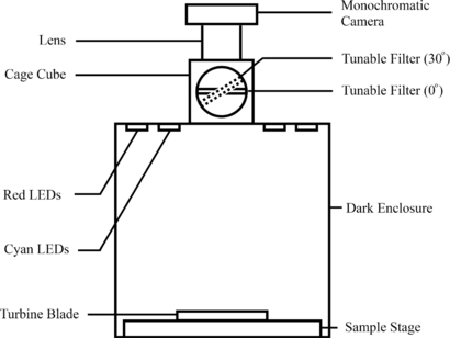
Figure 2. Diagram of the imaging system.
Download figure:
Standard image High-resolution imageFigure 3 shows the system's LED array consisting of two LUXEON® rings (Philips) containing a total of 18 cyan LEDs surrounded by 4 red LEDs. The array has two functions, (1) to excite ruby fluorescence with cyan illumination and (2) to allow reflected-light images to be acquired under red illumination. While any wavelength shorter than the R1 and R2 lines can stimulate ruby fluorescence, cyan LEDs have a low red light component which can be readily filtered to prevent reflected red light masking ruby fluorescence. The cyan LEDs are fitted with cyan subtractive dichoric filters (Edmund Optics® QuickMod™) to block unwanted wavelengths emitted by the LEDs. The cyan array produces a power density of 5.75 mW cm−1 at 505 nm at the sample stage.
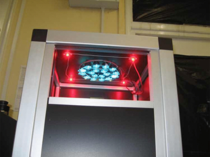
Figure 3. Imaging system interior: red LEDs and LUXEON rings of cyan LEDs fitted with cyan subtractive dichoric filters.
Download figure:
Standard image High-resolution image3. Confounding factors
Turbine blades accumulate a range of surface contaminants in-engine such as oxides, salts and combustion products [11]. In addition to in-engine contaminants, inspectors highlight regions of interest with permanent marker during repair and overhaul. The contaminants have the potential to confound the imaging process by masking the alumina or fluorescing in the same spectral band as ruby fluorescence. When two photoluminescent materials, which fluoresce in the same spectral band, are imaged, both materials contribute to the image making it difficult to distinguish between them. However, ruby fluorescence emits over an exceptionally narrow spectral range, in contrast to typical photoluminescent materials which exhibit broadband fluorescence. The narrow spectral range of ruby fluorescence is used to distinguish alumina from fluorescent contaminants by incorporating a tunable bandpass filter into the imaging system; the fluorescence spectra in figure 5 compares fluorescence spectra acquired from alumina and red permanent marker on a turbine blade shown in figure 4. The ruby fluorescence R1 and R2 lines are common to both spectra; however, the spectra acquired from the permanent marker has broadband background fluorescence in addition to the R1 and R2 lines. The bandpass of the tunable filter at 0° and 30° is superimposed on the spectra, illustrating that by acquiring images at two adjacent spectral bands (including and excluding the R1 and R2 lines), ruby fluorescence appears in one image and broadband fluorescence appears in both. This facilitates the identification of fluorescent contaminants and their subsequent removal via image subtraction to produce an alumina-only fluorescence image.
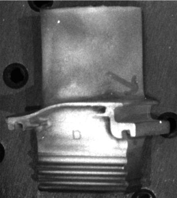
Figure 4. Reflected-light image of a turbine blade representative of the Series-1 blades provided by Rolls-Royce plc annotated with an arrow in red permanent marker.
Download figure:
Standard image High-resolution image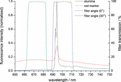
Figure 5. Fluorescence spectra acquired from alumina and red permanent marker on a Series-1 turbine blade with a Renishaw Ramascope 2000. The ruby fluorescence R1 (694.3 nm) and R2 (692.9 nm) peaks are prominent in the alumina spectrum, and to a lesser extent in the red marker spectrum. The red marker spectrum has a high background associated with broadband fluorescence from the permanent marker. The wavelengths transmitted by the VersaChrome filter at 0° and 30° are superimposed on the fluorescence spectra, illustrating how the imaging system distinguishes between ruby fluorescence and background fluorescence.
Download figure:
Standard image High-resolution imageThe fluorescence spectra were acquired with a Renishaw Ramascope 2000 (Renishaw plc) with a HeNe laser excitation source (λex = 632.8 nm). Although a HeNe laser can excite ruby fluorescence to produce a spectrum, illuminating an entire sample for fluorescence imaging would produce an undesirable speckle pattern which would introduce an additional confounding factor.
4. Experimental details
Rolls-Royce plc provided two example series of turbine blades from to test the capabilities of the imaging system. Both series of turbine blades were inspected for mechanical damage, and annotated to indicate regions of interest at a Rolls-Royce plc repair and overhaul facility before being imaged in the system. The Series-1 blades were provided in their in-engine condition representing blades entering the repair and overhaul process while the Series-2 blades were washed, degreased and chemically stripped in sulphamic and nitric acid representing blades which have undergone the initial stages of the repair process.
The imaging process acquires three images of each side of a turbine blade. The first image is a reflected light image of the blade acquired under red illumination providing a representative image of how the blade appears by-eye, albeit in grey-scale. The second image is a fluorescence image acquired under cyan illumination with the tunable filter set to an angle of 0°, capturing ruby and background fluorescence. The final image is a fluorescence image acquired under cyan illumination with the tunable filter set to an angle of 30°, capturing background fluorescence only. Each image is acquired over 10 s.
The imaging software produces an alumina map, showing the location of alumina on a turbine blade by subtracting the 30° image from the 0° image, thereby removing a significant proportion of the contaminant fluorescence from the image. The background-subtracted image can be compared to the reflected light image to identify where remnant alumina resides on a blade. The background-subtracted image retains a small component of background fluorescence since the intensity of the background varies between the two spectral bands measured. However, the magnitude of the remaining background is insignificant compared to the initial signal.
A focused ion beam (FIB) microscope (FEI Company) was used to mill a cross-section into a region of a sample which demonstrated ruby fluorescence to illustrate the presence of alumina.
5. Results
Figure 6 illustrates the four stages of the imaging process on a Series-1 turbine blade from the Rolls-Royce samples. The reflected light image in figure 6(a) shows an arrow drawn on the aerofoil in red permanent marker during the repair and overhaul inspection. The 0° image in figure 6(b) shows fluorescence from the permanent marker and alumina. The 30° image in figure 6(c) shows that by tuning the filter, the alumina fluorescence intensity has significantly decreased while the contaminant fluorescence is clearly visible. The processed image in figure 6(d) shows the 30° image subtracted from the 0° image, providing a map of alumina on the turbine blade. Figure 6 demonstrates that the imaging system is capable of detecting alumina on turbine blades by distinguishing ruby fluorescence from contaminant fluorescence.

Figure 6. A typical Series-1 turbine blade: a reflected light image showing a red arrow annotating the blade (a). A fluorescence image with the filter tuned to 0° showing contaminant and ruby fluorescence (b). A fluorescence image tuned to 30° showing contaminant fluorescence only (c). The background-subtracted image showing remnant alumina is produced by subtracting the 30° image from the 0° image (d).
Download figure:
Standard image High-resolution imageFigure 7 shows a typical Series-2 turbine blade from the Rolls-Royce samples. A turbine blade annotated in red permanent marker prior to the stripping process is shown in figure 7(a). Figure 7(b) shows that the annotation is not visible after the immersive chemical stripping process. Figure 7(c) shows that a fluorescent component of the permanent marker had not been removed by the stripping process, illustrating that the imaging system is capable of detecting fluorescent contaminants invisible to visual inspection.

Figure 7. Typical Series-2 turbine blade: the colour image shows a turbine blade annotated with red permanent marker (a). The reflected light image shows the same blade after immersive chemical stripping demonstrating that the annotation is no longer visible (b). The fluorescence image shows that a fluorescent component of the permanent marker has resisted the stripping process (c).
Download figure:
Standard image High-resolution imageThe light region in the centre of figure 8(a) shows where a FIB has milled into a sample exhibiting ruby fluorescence. This region is brighter than the surrounding area as the FIB has milled through the electrically insulating alumina layer to the underlying conductive intermetallic aluminde. Figure 8(b) shows a FIB image of the face of the cross-sectioned sample. The black (electrically insulating) band which runs horizontally across the image is a layer of alumina on the surface of the sample. The thick band on top of the alumina is a strap of platinum, deposited in the FIB microscope to prevent the ion beam from removing the alumina while milling the cross-section.

Figure 8. FIB images of a sample which exhibits ruby fluorescence: the light region in the centre of (a) shows where a cross-section has been milled into the sample. The surrounding darkness indicates that the surface is electrically insulating. The black band running horizontally across (b) is a layer of alumina on the surface of the sample under a deposited strap of protective platinum.
Download figure:
Standard image High-resolution image
6. Discussion
The results demonstrate that the imaging system is capable of detecting residual alumina via LED-induced fluorescence imaging. Optical fluorescence spectroscopy has been used to confirm that the observed fluorescence originates from alpha alumina by detecting the characteristic R1 and R2 peaks. The system can inspect an entire turbine blade in approximately 60 s, assuming 10 s image acquisitions.
Furthermore, the results illustrate that the tunable filter enables the system to distinguish between ruby and background fluorescence, allowing background-subtracted alumina-maps to be produced. This function is critical since it has been shown that fluorescent contaminants such as permanent marker are commonly applied to turbine blades during repair and overhaul inspections.
The images acquired from the Series-2 turbine blades revealed the presence of contaminants which were invisible to visual inspection. Annotations made with a permanent marker disappeared after the turbine blade had been chemically stripped, indicating the successful removal of the permanent marker; however, the imaging system revealed fluorescent components of the marker which had resisted the stripping operation. This result demonstrates that contaminants can exist on turbine blades which cannot be detected with existing inspection methods.
A key benefit on the system—which cannot be achieved via visual assessment—is that it produces an electronic record of each inspection, providing evidence that alumina and other contaminants have been detected and subsequently removed. Therefore, it is possible for an electronic record to accompany an individual turbine blade over its service lifetime.
The images output by the system can be digitally processed to provide a range of data from each inspection e.g. the surface area of a blade contaminated with alumina. This data could be used to objectively sentence turbine blades with image analysis software with pass/fail thresholds determined by the original equipment manufacturer. Using the data in this capacity would allow the system to be fully automated, reducing the time associated with loading/unloading turbine blades and manually adjusting optics.
7. Conclusions
The imaging system provides a superior method of objectively detecting alumina on turbine blades undergoing repair and overhaul inspections. The results demonstrate that the system is capable of rapidly detecting alumina and is able to distinguish between alumina and other fluorescent surface contaminants. The system produces an electronic record of each inspection with images which may be processed to provide data for automated component sentencing. The system would be improved by automating the rotation of the filter and turbine blade.
Acknowledgments
The authors extend their thanks to Peter Heard for providing his expertise in FIB, and to the staff and students of the Interface Analysis Centre, University of Bristol and Rolls-Royce plc. This work is funded by Rolls-Royce plc and EPSRC.