
Abstract
Due to trends in aero-design, aeroelasticity becomes increasingly important in modern turbomachines. Design requirements of turbomachines lead to the development of high aspect ratio blades and blade integral disc designs (blisks), which are especially prone to complex modes of vibration. Therefore, experimental investigations yielding high quality data are required for improving the understanding of aeroelastic effects in turbomachines. One possibility to achieve high quality data is to excite and measure blade vibrations in turbomachines. The major requirement for blade excitation and blade vibration measurements is to minimize interference with the aeroelastic effects to be investigated. Thus in this paper, a non-contact—and thus low interference—experimental set-up for exciting and measuring blade vibrations is proposed and shown to work. A novel acoustic system excites rotor blade vibrations, which are measured with an optical tip-timing system. By performing measurements in an axial compressor, the potential of the acoustic excitation method for investigating aeroelastic effects is explored. The basic principle of this method is described and proven through the analysis of blade responses at different acoustic excitation frequencies and at different rotational speeds. To verify the accuracy of the tip-timing system, amplitudes measured by tip-timing are compared with strain gage measurements. They are found to agree well. Two approaches to vary the nodal diameter (ND) of the excited vibration mode by controlling the acoustic excitation are presented. By combining the different excitable acoustic modes with a phase-lag control, each ND of the investigated 30 blade rotor can be excited individually. This feature of the present acoustic excitation system is of great benefit to aeroelastic investigations and represents one of the main advantages over other excitation methods proposed in the past. In future studies, the acoustic excitation method will be used to investigate aeroelastic effects in high-speed turbomachines in detail. The results of these investigations are to be used to improve the aeroelastic design of modern turbomachines.
Export citation and abstract BibTeX RIS

Content from this work may be used under the terms of the Creative Commons Attribution 3.0 licence. Any further distribution of this work must maintain attribution to the author(s) and the title of the work, journal citation and DOI.
1. Introduction
The first time engineers encountered serious problems caused by aeroelasticity in the field of manned aviation was when phenomena like divergence and flutter resulted in rapid structural failure of the wing. Since those days, great effort has been made to predict and reduce the risk of failure caused by aeroelastic effects in manned aviation and other applications of turbomachinery. Beside the inherent excitation mechanisms found in turbomachines, like forced response to upstream wakes and the potential flow interaction of downstream blades, several trends in turbomachinery development increase the risk of blade failure due to high cycle fatigue. The most dominant driver of these developments is the ambition to achieve power density. For jet engines, this leads to higher aerodynamic loading due to the effort to reduce weight by decreasing the number of stages. Transonic flow makes modern turbomachines compact but also prone to shocks and flow separation, increasing the risk of blade failure by flutter.
Vogt (2005) as well as Marshall and Imregun (1996) already stated that one of the major challenges in aeroelastic research is to tackle the lack of experimental data. While an extensive data base exists for two-dimensional test cases, published for example by Bölcs and Fransson (1986), experimental data under engine-like conditions can be rarely found in the open literature. Especially, nowadays where the computational resources allow more sophisticated numerical predictions of aeroelastic effects, experimental data for code validation become more and more important.
One possibility for investigating aeroelastic effects and to generate experimental data under engine-like conditions is to use rotating test rigs whose instrumentation includes systems for exciting and measuring blade vibration. Different approaches for exciting rotating turbomachinery blades have been published in the past. For example, Morrison et al (2005) present an excitation system based on electromagnetic forces. They investigate a single-stage rotor in a spin rig. The bearing is electromagnetic and can be used to excite the rotor to rigid body motion. By investigating the rotor under vacuum conditions, the aerodynamic influence on the vibration behavior is eliminated. Their approach of exciting blade vibrations by electromagnetic forces is also used by other authors. Rice et al (2007) develop a high voltage ac magnetic drive to excite blade vibrations in a steam turbine. The electromagnetic exciters are mounted in the casing directly above the rotor row and generate a pulsating magnetic field. The rotor blades exhibit a periodic force and thus vibrations are excited. One of the major challenges of the electromagnetic system is the temperature of the exciters during operation. Therefore, the exciters were cooled actively.
Another approach for exciting turbomachinery blades is using piezoelectric actuators. One of the first studies using piezoelectric excitation is presented by Fabunmi (1978) who applied this method to a single-stage axial compressor rotor. Since the first use of piezoelectric actuators for exciting blade vibrations in turbomachines, this approach has been employed by several researchers. Kielb and Abhari (2003) investigate the aeroelastic behavior of the rotor blades of a single-stage turbine. This test rig is instrumented with strain gages for blade vibration measurements and piezoelectric actuators for blade excitation. The instrumented rotor can be investigated under vacuum conditions as well as in the presence of a typical turbomachinery flow. In the latter case, the flow is generated by a shock tube limiting the measurement time to 50–100 ms.
Piezoelectric excitation was also used by Siemann et al (2009) and Goltz et al (2009). They developed an excitation system, which is based on piezoelectric actuators and tested in a low-speed axial compressor. As a novelty, Siemann et al (2009) present a control loop for exciting blade vibrations at a specific amplitude and create a specific phase shift between the vibrations of adjacent blades (interblade phase angle). Subsequently, the developed excitation system was used by Belz et al (2013) for exciting a fan blisk. In their study, the blade vibration amplitudes of the first eigenmode achieved by piezoelectric excitation are presented and the constraints of the piezoelectric approach under engine-like operating conditions are discussed.
Further work on the excitation of turbomachinery blades by Holzinger et al (2009) explores different approaches for exciting turbomachinery blades of which the most promising one is deemed the axial injection of air, despite the resulting interference with the flow. This hydrodynamic excitation system is used in an axial compressor by Wegman et al (2013) to demonstrate its applicability to turbomachinery blades. The maximum excitation frequency is 3200 Hz, while nodal diameters (NDs) from −3 to +3 can be excited.
In addition to other excitation approaches for rotating turbomachinery blades, exciting blade vibrations acoustically provides, in the present authors' opinion, an attractive alternative for investigating aeroelastic effects experimentally. Using sound to excite turbomachinery blades avoids additional mistuning because it requires no contact. It also offers the flexibility of freely choosing the phase of the generated acoustic signal and—within limits—the excitation frequency and the excited blade vibration amplitude. Thus, a novel acoustic excitation method for rotating turbomachinery blades is described in this paper. The basic idea of this excitation method—described in detail in section 3—is to use several acoustic sources for generating an acoustic field that forces blade vibrations. These vibrations are measured and analyzed by the tip-timing method. The capabilities of the tip-timing system for aeroelastic studies are validated and the high accuracy of measured blade vibration amplitudes is proven.
2. Theory
The approach to exciting rotating turbomachinery blades presented in this paper is based on acoustics. To give a deeper insight into the physics of this method, background information about sound propagation in turbomachines is provided in the first part of this section. Subsequently, the importance of the interblade phase angle for aeroelastic effects is outlined in subsection 2.2. Finally, the connection between the acoustic pressure and the resulting blade vibrations in the presence of acoustic excitation is described.
2.1. Acoustics
Sound can be described as a pressure perturbation whose amplitude is in most cases small compared to ambient pressure. Based on this assumption, sound propagation in a continuum can be described by the acoustic wave equation:
The left-hand side characterizes the change in time and space of a small pressure perturbation p' and defines the wave dynamics. It depends on the speed of sound a, the second derivative of p' with respect to time t and on the divergence of the sound pressure gradient ∂p'/∂xi. Q on the right-hand side represents all acoustic sources in the considered volume. In turbomachines, the sound field is bounded by the hub, defined by the radius rhub, and the shroud, defined by the radius rshroud, of the flow channel. Thus, the boundary conditions differ from sound propagation in the free field. Usually, an annular channel with acoustically hard walls is used to approximate the flow path of turbomachines. In order to describe the complex sound field in an annular channel, a modal approach can be used. In this case, the sound field theoretically consists of different modes, which can be characterized by the order in azimuthal (m) and in radial (n) directions. m defines the number of sound pressure cycles in the circumferential direction. The radial mode order n represents the number of sound pressure nodes (zero pressure zones) in the radial sound pressure distribution. Finally, the overall sound field in an annular channel can be described by the superposition of all propagating modes. Some examples of instantaneous pressure distributions of low-order modes in an axial plane of an annular channel are illustrated in figure 1.
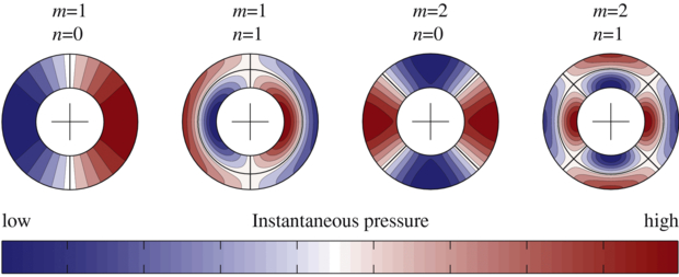
Figure 1. Instantaneous pressure distribution in an axial plane of an annular channel for different acoustic modes.
Download figure:
Standard image High-resolution imageTo describe the sound propagation of a defined acoustic mode in an annular channel with a uniform air flow velocity W, the homogeneous convective wave equation
with

can be solved by using a harmonic separation approach. The resulting equation
given by Munjal (1987), defines the dependence of the sound pressure p' on the geometric position in the annular channel and its dependence on time. In this case, ω denotes the angular frequency of the oscillating acoustic pressure. The acoustic pressure distribution in the radial direction is described by a linear combination of the first and second kinds of Bessel function:
Further variables of equation (4), like the acoustic mode amplitudes  and
and  as well as the axial wave number
  defined by
are mode dependent. Thus, they must be determined for each mode and each frequency participating in the sound field. The axial wave number  depends on the wave number k = ω/a, the axial Mach number Maz and the eigenvalues ξmn.
An important criterion for sound propagation in annular channels is the cut-off frequency fcutoff. This parameter indicates whether acoustic modes are damped or propagable. It can be deduced by the interpretation of the exponents of the exponential functions in the axial propagation part of equation (4). The cut-off frequency is defined by

where ξmn are mode-dependent eigenvalues for the radial pressure distribution in the case of acoustically hard walls:
In conclusion, the cut-off frequency depends on the order of the considered mode given by m and n, the speed of sound a, the outer radius of the considered annular channel rshroud, the axial Mach number Maz and the hub-to-shroud ratio rhub/rshroud. All modes propagating with a frequency below the cut-off frequency are damped in the far field.
Finally, the overall sound field within an annular channel can be calculated for a defined frequency by the superposition of all participating modes:
A more detailed description of the governing equations for sound propagation in annular channels is given, for example, by Ghiladi (1981). In order to take into account the swirl of the turbomachinery flow, equations (6) and (7) must be changed slightly according to Lohmann (1977).
On one hand, the theory of acoustics discussed in this subsection is used for evaluating the sound propagation inside the acoustic excitation units (AEUs) (see section 3). On the other hand, it is used to determine the propagation behavior of the acoustic modes generated by the acoustic excitation system (AES) and exciting blade vibrations (see subsection 5.2). In both cases, the calculation of the cut-off frequencies of the considered acoustic modes is necessary.
2.2. Aeroelasticity
The main aeroelastic effects in turbomachines are forced response and flutter. For both phenomena, the aerodynamic damping has a significant impact. In the case of forced response, the resulting vibration amplitude is inversely proportional to the overall damping in the system. In the case of flutter, the aeroelastic instability results from negative aerodynamic damping. One of the main drivers for aerodynamic damping in turbomachines is the interblade phase angle σ, which defines the phase shift between the vibrations of adjacent blades in turbomachinery cascades. This parameter is based on the cyclic symmetry of turbomachinery cascades. Due to the cyclic nature, blade vibrations propagate in turbomachines as so-called 'traveling waves'. These vibration modes can be characterized by the interblade phase angle or the ND. In analogy to the azimuthal order of acoustic modes, the latter parameter defines the number of oscillation cycles of the blade vibration amplitude in the circumferential direction. The dependence between the interblade phase angle and the ND is given by

where Nblade represents the number of blades of the considered blade row. The crucial importance of σ is illustrated by an example for aeroelastic stability shown in figure 2. A typical s-curve can be observed. Depending on the interblade phase angle of the blade row vibration, the aeroelastic stability will be positive or negative. In the latter case, the system will be prone to self-excited vibrations, e.g. flutter, which results in increasing blade vibrations leading to a substantial increase of the dynamic stress in the blade material. Due to the importance of σ, the possibility of exciting different interblade phase angles is an important requirement for the experimental investigation of aeroelastic effects.
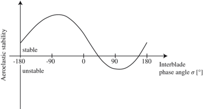
Figure 2. Example of the dependence of the aeroelastic stability on the interblade phase angle.
Download figure:
Standard image High-resolution image2.3. Acoustically excited blade vibrations
Assuming well-separated eigenfrequencies for a turbomachinery blade, the blade vibration behavior can be described by a modal approach. The equation of motion for a one degree of freedom model representing, for example, the first bending mode of a turbomachinery blade is given by

where m denotes the mass, c the mechanical stiffness and d the sum of the material and the structural damping of the turbomachinery blade. Additionally, the aerodynamic mass Am, the aerodynamic stiffness Ac and the aerodynamic damping Ad influence the eigenfrequency and the eigenmode of the considered system. The excitation of this system is given by the right-hand side. In the case of acoustic excitation, the mechanical system is forced to vibrations by a periodical force caused by the acoustic pressure. Therefore, the connection between the acoustic field generated by the AES and the blade dynamics can be found in the forcing function on the right-hand side of equation (12). The amplitude  is then given by the product of the acoustic pressure acting on the blade multiplied by the blade surface. Furthermore, the excitation frequency Ω is defined by the frequency of the acoustic pressure. If this frequency equals the eigenfrequency of the considered system, the resonance condition is fulfilled and blade vibrations can be observed.
3. Development of an acoustic excitation system for rotating turbomachinery blades
The feasibility of using sound to excite non-rotating turbomachinery blades was shown by different authors (Jones and Cross 2002, Judge et al 2003). The next step in the development of using sound for aeroelastic investigations is the excitation of rotating turbomachinery blades. This step is necessary for quantifying the aerodynamic damping term Ad in equation (12). The basic idea is to mount several AEUs directly above the rotor row, which shall be excited. These units are equispaced in circumferential direction and are used to generate an acoustic field, which in turn excites blade vibrations. In order to take all the different requirements and challenges into account, the system is developed in four steps. The AEUs consist of two compression drivers and a horn. In the first step, the horn geometry is designed and optimized under consideration of different requirements. Concerning the diameter of the horn outlet, contradictory requirements exist. With respect to a low impact on the flow field in the tip area of the rotor blades, the diameter of the horn outlet should be as small as possible. On the other hand, the emitted acoustic energy exciting the blades decreases with decreasing diameter of the horn outlet. A compromise is found in choosing a small outlet diameter while a sufficient amount of acoustic energy for blade excitation is provided by using two compression drivers for each horn. For an efficient superposition of the two acoustic sources, different horn geometries are investigated. The final design is based on a low angle between the symmetry axes of the two compression drivers for a smooth transition at the point of combination of the two acoustic sources. Furthermore, the diameter at the combination point must be small compared to the wavelength of the acoustic wave. In doing so, the occurrence of interference and reflections can be avoided. A general requirement, which is considered during the whole design process of the horn geometry, is the cut-off frequency of mode m = 1, n = 0. For the entire frequency range needed for the blade excitation, this mode is cut-off. Consequently, the sound propagation in the horn geometry can be described by a plane wave and the whole AEU can be modeled by a monopole source. This assumption is the basis for the physical interpretation of the acoustic excitation of rotating turbomachinery blades later on.
In the second step of the development process, the effect of turbomachinery flow on the acoustic excitation is investigated. This investigation is performed at the Aeroelastic Test Rig at KTH in Stockholm. Since this rig is an annular cascade, blade rotation is neglected. The results of this study confirm that the acoustic excitation method is a suitable method for exciting blades in the presence of typical turbomachinery flow conditions (Freund et al 2013). Freund et al (2013) demonstrate the acoustic excitation of blade vibrations for exit Mach numbers up to 0.5. The directivity of the acoustic excitation is varied with the orientation of the horn axis with respect to the blade. The presented results are transferred to the design of AEUs in rotating turbomachines. The flow velocity, relative to the rotating blades, remains the most important parameter for the influence of the flow on the acoustic excitation. Based on the results of Freund et al (2013), an optimal set of parameters is determined and used for the proof of principle (PoP) of exciting rotor blades acoustically.
The development of the acoustic excitation control is the main content of step 3. The number of excitation units for the excitation system used in an axial compressor is defined by geometrical constraints, on one hand, and by the ambition to provide as much acoustic energy for blade excitation as possible, on the other hand. Therefore, the final design of the excitation system used consists of eight excitation units. This is the maximum number of excitation units, given the geometrical constraints due to the dimensions of the excitation units and of the flanges of the axial compressor casing modified for the present study. The basic principle of the system developed for controlling the excitation units is outlined in figure 3. The main task of the control system is to generate a sine function with a defined amplitude, frequency and phase for each excitation unit. This signal is generated by a field-programmable gate array (FPGA) programmed in LabVIEW. The FPGA provides a high output sampling rate of 500 MHz. The control software controls amplitude, frequency and phase settings for all excitation units. The generated sine signal is amplified for each compression driver using a standard stereo amplifier. One of the main advantages of this control concept is that all excitation units can be controlled individually. This provides the opportunity to apply a phase shift between the sine signals of adjacent AEUs, which is of significant benefit for the experimental investigation of aeroelastic effects as shown in section 5.

Figure 3. Concept of the control system for acoustic excitation.
Download figure:
Standard image High-resolution imageBy measuring and comparing the generated acoustic signal of different excitation units operated with the same voltage supply, maximum deviations of 0.27 dB for the sound pressure level and 3.1° for the phase are observed within a 95% confidence interval. The reason for such variations can be found in manufacturing and electrical tolerances of the AEUs and their voltage supply. In the future, it is planned to investigate the influence of these variations on the acoustic excitation method and to implement—if necessary—calibration factors.
The fourth and the final step in the development process is the PoP of acoustic excitation of rotating turbomachinery blades. It is performed in a low-speed axial compressor (LSAC), which is described below in section 4.
4. Test setup
To show the feasibility of exciting rotating turbomachinery blades acoustically and to investigate the potential of this method for aeroelastic studies, the excitation system is applied to the second rotor row of the LSAC. A schematic overview of the LSAC is shown in the upper part of figure 4. This axial compressor consists of 2.5 stages. The two stator and rotor rows as well as the inlet guide vanes are NACA profiled. The flow enters the compressor through a bellmouth, which is used for the mass flow measurement. The annular cross section has a constant inner and outer diameter, such that the blade height is 140 mm. Following the compressor, a diffuser reduces the kinetic energy of the fluid into a pressure increase. The diffuser is completed by a throttle that can be closed incrementally to increase the total pressure ratio. Due to the low stiffness of the rotor blades, high vibration amplitudes can be achieved if active excitation is applied. Hence, this rig is ideally suited for the development of excitation methods. The LSAC is operated in a closed circuit, which means that fluid is cooled by an air cooler after compression and before entering the compressor again. This operating mode provides constancy and a high repeatability of the inlet conditions. An overview of the main parameters of the LSAC is given in table 1.

Figure 4. Schematic overview of the low-speed axial compressor (above), final test setup (below).
Download figure:
Standard image High-resolution imageTable 1. Low-speed axial compressor parameters.
| Design speed n | 3000 rpm |
Mass flow  |
16.5 |
| Total pressure ratio π | 1.08 |
| Hub diameter d | 480 mm |
| Blade height s | 140 mm |
| Number of IGV blades | 20 |
| Number of stator blades | 26 |
| Number of rotor blades | 30 |
The final test set-up for this study is shown in the lower part of figure 4. For measuring the blades' response to the AES, an optical tip-timing system is applied. Tip-timing is a well-known method based on the measurement of the time of arrival of the rotating blades. If blade vibrations occur, deviations in the time of arrival are measured compared to the non-vibrating condition. Utilizing this offset in the time of arrival, the blade vibration can be characterized in terms of amplitude, frequency and phase. In this study, the blade eigenfrequencies are determined with a numerical modal analysis before the tests. With this information, the eigenmode of the measured blade vibration can be identified. The tip-timing system used for this study is built by Agilis® and consists of eight optical probes, a laser, a detector box and a computer for data acquisition and processing. The tip-timing probes are unlensed, purged by cooling air and distributed circumferentially. The probe positions were optimized with respect to the rotor blade eigenfrequencies and the expected synchronous excitation events. All tip-timing probes are located at a single axial plane at the rotor trailing edge, which gives high data density of eight measurements per revolution. Using tip-timing, every eigenmode causing a deflection of the blade tip in circumferential direction can be captured. Since the rotor blades in turbomachines are usually staggered, even axial bending modes deviate the measured time of arrival and can thus be measured.
The combination of the acoustic excitation and the tip-timing system provides a test set-up for the investigation of aeroelastic effects. It is free of undesirable contact such that properties of the blades like stiffness and mass, which are important for vibration characteristics, are not influenced. The tip-timing system is capable of capturing the vibration responses of all blades and thus offers an opportunity to measure the system behavior of the rotor cascade in terms of traveling wave modes.
To ensure accuracy of the tip-timing system, a validation against strain gages is performed on the LSAC. In this study, the first eigenmode of the blade is excited by piezoelectric actuators at different rotational speeds. Siemann et al (2009) describes the present piezoelectric excitation system in detail. While the intensity of excitation is varied, the blade vibration amplitude is measured by the tip-timing system and strain gages. The strain gages are positioned at locations of high strain on the surface on the rotor blade. The distribution of the surface strain is calculated by a finite element method simulation. The voltage needed for the blade excitation and the voltage signal from the blade vibration measurement is transferred to the rotating system by a slip ring. It is found that very high accuracy can be achieved by tip-timing. The ratio between the blade vibration amplitudes measured by tip-timing and measured by strain gages is 0.97 ± 0.07 at 95% confidence. Furthermore, the deviation between the detected blade vibration frequencies is smaller than ±0.4 Hz at 95% confidence. Based on these promising results, the tip-timing system is chosen to be combined with the acoustic excitation method for the investigation of further aeroelastic effects in turbomachines.
5. Results
This section consists of three main parts. First, the feasibility of exciting rotor blades acoustically is shown at different rotational speeds. Secondly, the relationship between the control and the number of AEUs, the developing sound field and the excited blade vibrations is explained. Based on these findings, an approach to exciting different ND at a defined operating point is developed and proven by experimental results in the last part of this section.
All results presented below are based on the excitation and analysis of the first bending mode of the LSAC rotor blades. The first six eigenfrequencies of the rotor blades determined by numerical modal analysis are summarized in table 2.
Table 2. Calculated rotor blade eigenfrequencies.
| Eigenfrequency (Hz) | ||||
|---|---|---|---|---|
| Speed | ||||
| Eigenmode | 0 rpm | 1000 rpm | 2000 rpm | 3000 rpm |
| 1F (bending) | 358 | 359 | 363 | 370 |
| 2F (bending) | 1416 | 1416 | 1418 | 1422 |
| 1T (torsion) | 1640 | 1641 | 1643 | 1647 |
| 1E/F (edge/bending) | 2738 | 2738 | 2740 | 2743 |
| 3F (bending) | 3877 | 3878 | 3880 | 3884 |
| 2T (torsion) | 4518 | 4520 | 4524 | 4530 |
5.1. Acoustic excitation of rotating turbomachinery blades—proof of principle
In order to prove the feasibility of acoustic excitation in turbomachines, the LSAC rotor blades of the second stage are excited acoustically at different rotational speeds. Figure 5 shows the blade responses of the second rotor row of the LSAC caused by acoustic forcing at different rotational speeds. The peak-to-peak blade vibration amplitudes are determined by a least square model fit (LSMF). The most important input parameter for the LSMF analysis is the blade vibration frequency. This parameter is determined by a fast Fourier transformation (FFT) of individual blade responses for all cases presented in this paper. To compensate for the difference between the real blade vibration amplitude and the vibration amplitude observed by tip-timing, all tip-timing amplitudes are processed by using the local chord angle at the instrumented axial position of the rotor blade. All LSMF amplitudes are normalized by the axial chord length of the rotor blade.

Figure 5. Measured vibration amplitudes at different rotational speeds.
Download figure:
Standard image High-resolution imageFor the PoP, the acoustic excitation is activated approximately 10 s after the measurement of the vibration amplitude is started and operated for a period of 10 s. Cascade responses can be clearly observed for each rotational speed. In this case, the same amplitude and frequency is set for each excitation unit. While the amplitude of the voltage supply is controlling the generated sound pressure, the frequency represents the acoustic excitation frequency and has to be set with respect to the blade eigenfrequencies. The excitation units operate in phase, i.e., there is no phase shift between the sine signals of adjacent excitation units. The chosen amplitude of the excitation unit voltage supply results in a sound pressure level output between 144 and 158 dB for each excitation unit. These values are determined in an anechoic chamber with a microphone placed directly in front of the AEUs. The defined distance between the microphone and the horn outlet is representative of the distance between the horn outlet and the blade tips in the LSAC. Caused by the characteristic transfer behavior of the compression drivers and the horn geometry, the generated sound pressure level strongly depends on the operating frequency of the compression drivers. The frequency which must be set in order to excite the blades depends on the rotational speed, the eigenfrequency of the blades and the acoustic field caused by the acoustic excitation. A detailed explanation of the relationship between the acoustic excitation frequency and the resulting blade vibration frequency is given in the second part of this section. The observed blade vibration frequencies fblade and the frequencies of the AES fAES during the PoP are given in figure 5.
It can be seen that the acoustic forcing results in a blade excitation at a defined frequency for the results presented in figure 5. Due to mistuning, the amplitude of blade vibration varies from one blade to another. In this case, mistuning means that the eigenfrequencies differ from one rotor blade to another. Hence, the excitation frequency does not match the blade eigenfrequency of all blades. The observed maximum blade response changes as the rotational speed increases. The highest vibration amplitude occurs at 2000 rpm at blade 9. One reason for mistuning and the different levels of excitable amplitude is the design of the LSAC rotor. The rotor blades are connected to the disc by a retaining ring, which is axially screwed onto the disc and shown in figure 6. In this type of attachment, the boundary conditions and the mechanical damping differ from blade to blade. This latter key parameter impacts the level of forced response of the rotor blades and it changes with rotational speed due to the change of centrifugal force. An impact of not calibrating the AEUs on the amplitude distribution can be excluded because each measured blade vibration amplitude is averaged over one revolution. Since the AEUs are fixed to the casing, all blades are passing through the same acoustic field and experiencing the same excitation force during each revolution.

Figure 6. Blade-disc connection of the LSAC.
Download figure:
Standard image High-resolution imageIn summary, exciting rotating turbomachinery blades using acoustics is feasible. This PoP is the basis for the application of acoustic excitation to subsequent aeroelastic studies in turbomachines.
5.2. Physics of the acoustic excitation method
Comparing the acoustic excitation frequency to the blade vibration frequency, a factor of two or even higher can be observed. This shift in frequency cannot be explained by the rotational speed of the rotor blades and the resulting Doppler effect alone. In fact, an additional velocity component must be considered caused by the developing acoustic field. Since the LSAC is not instrumented for a detailed analysis of the acoustic field, the blade vibration measurements are used to develop a deeper understanding of the dominant modes of the acoustic field caused by the excitation system. In theory, the vibration behavior of the rotor row, which is characterized by the number of NDs, represents an image of the excitation pattern. This means that the number of NDs can be directly related to the azimuthal order of the dominant acoustic mode. Therefore, the blade responses presented in figure 5 are analyzed by traveling wave analysis. The results of the traveling wave analysis are shown in figure 7 for different rotational speeds. All traveling wave results are given in terms of the amplitude of the displacement at the tip of the excited rotor blade normalized by the axial chord length.
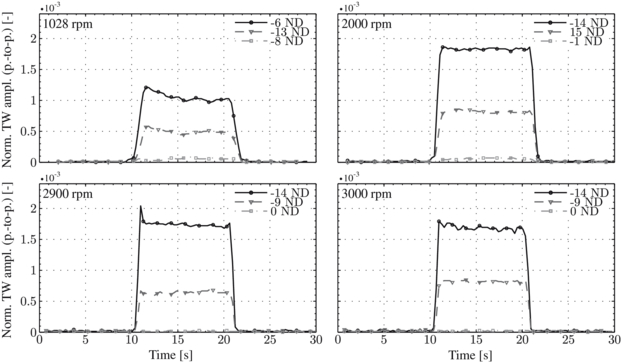
Figure 7. Measured traveling wave amplitudes at different rotational speeds.
Download figure:
Standard image High-resolution imageFor all rotational speeds, the content of traveling wave mode amplitudes is described by plotting the time-dependent amplitude of three different NDs. The first plotted traveling wave mode is the main component with the highest measured vibration amplitude. Due to the fact that the rotor cascade is mistuned, the vibration energy is not concentrated in a single traveling wave mode. To characterize the vibration behavior more completely, the upper and the lower limits of the amplitudes of the remaining traveling wave modes are plotted as well. For all rotational speeds, the system vibration behavior can be described by a backward traveling wave mode. The ND of the dominant traveling wave mode is −14 for all rotational speeds except the low speed case (1028 rpm). At 1028 rpm, the dominant traveling wave mode changes from ND = −14 to ND = −6. To obtain a more reliable data base for analyzing the relationship between the acoustic excitation frequency, the acoustic field and the system vibration behavior, a sweep of the acoustic excitation frequency is performed between 300 and 2000 Hz at 2000 rpm. In doing so, several blade responses are observed. Due to the well-separated eigenfrequencies of the investigated rotor, the excited modes are identified by the frequency of vibration, which is determined by the FFT of the recorded signals. In this case, only first bending mode responses are analyzed further. The main results of the traveling wave analysis of these responses to the AES are summarized in table 3, in addition to the cases presented in figure 7. In this table, the ND and the corresponding averaged amplitude represent the dominant traveling wave mode.
Table 3. Results of the traveling wave analysis.
| fblade (Hz) | fAES (Hz) | Nodal diameter | Norm. TW ampl. (averaged) (×10−3) | ||
|---|---|---|---|---|---|
| 1028 rpm | 346 | 758 | −6 | 1.05 | |
| 2000 rpm | 355 | 622 | 8 | 1.08 | |
| 355 | 888 | −14 | 1.83 | ||
| 355 | 1154 | −6 | 1.18 | ||
| 345 | 1413 | 2 | 0.69 | ||
| 2900 rpm | 360 | 1132 | −14 | 1.75 | |
| 3000 rpm | 363 | 1163 | −14 | 1.69 |
The comparison between the different blade responses at 2000 rpm shows that the ND of the excited mode can be changed by increasing the excitation frequency. Since the response of the blades is defined by the excitation pattern, it is presumed that the azimuthal order of the acoustic mode which is responsible for excitation can be determined by the ND of the vibration mode. In order to prove this hypothesis, the identified azimuthal orders are used to calculate the frequency of the acoustic pressure that is observed by the rotating blades. According to Petry (2011), the frequency acting on rotating turbomachinery blades can be calculated by means of the difference between the phase velocity of the exciting acoustic mode and the rotational speed of the blades. The phase velocity of an acoustic mode is given by

and is defined by the wavelength of the acoustic wave in the azimuthal direction divided by the time of oscillation of the acoustic wave T. Therefore, high phase velocities can be observed for low azimuthal orders. Using equation (13) to calculate the phase velocity, the frequency experienced by the rotor blades can be calculated as

The results for the transformation of the acoustic excitation frequency to the coordinate system of the rotor are summarized in table 4 for all cases. In fact, there are several acoustic modes, each characterized by the azimuthal order, which are able to excite a defined ND. For the 1028 rpm case, a ND = −6 response is observed. Depending on the direction of rotation of the acoustic mode, an azimuthal order of −6 or 24 can be linked to this ND. These values are determined under consideration of the number of LSAC rotor blades Nblade leading to


Equations (17) and (18) are based on the vibrational behavior of turbomachinery cascades characterized by aliased traveling wave responses for m > Nblade/2. Since the blade vibration frequency is lower than the acoustic excitation frequency, the rotational direction of the acoustic mode and the rotor must be the same (equation (15)). Consequently, ωphase and therefore m must be a positive number. This is why m = −6 can be excluded. In addition to m = 24, higher harmonic azimuthal modes, e.g.  , are also able to excite an ND of −6 but are of minor interest because the acoustic energy and therefore the potential to excite blade vibrations decreases with increasing azimuthal order. The comparison between the calculated (fAES, blade) and the measured blade vibration frequencies (fblade) shows good agreement for all cases (see table 4). Therefore, the determined azimuthal orders of the acoustic modes responsible for exciting the blades are assumed to be valid. Based on these findings, the basic principle of the presented acoustic excitation method is explained below.
Table 4. Results of frequency transformation.
| fAES (Hz) | ND | m | fAES, blade (Hz) | fblade (Hz) | ||
|---|---|---|---|---|---|---|
| 1028 rpm | 758 | −6 | 24 | 347 | 346 | |
| 2000 rpm | 622 | 8 | 8 | 355 | 355 | |
| 888 | −14 | 16 | 355 | 355 | ||
| 1154 | −6 | 24 | 354 | 355 | ||
| 1413 | 2 | 32 | 346 | 345 | ||
| 2900 rpm | 1132 | −14 | 16 | 359 | 360 | |
| 3000 rpm | 1163 | −14 | 16 | 363 | 363 |
The eight AEUs, which are assumed as circumferentially equally spaced monopole sources, excite an acoustic field. This field contains acoustic modes whose azimuthal order is given by an integer multiple of the number of AEUs. To excite the rotating blades, the acoustic excitation frequency must be adapted such that fAES, blade matches the blade eigenfrequency. The frequency shift between fAES and fAES, blade is caused by the relative velocity between the rotation of the acoustic mode responsible for blade excitation and the rotational velocity of the rotor.
A further conclusion can be drawn from the cut-off frequencies. Even under consideration of the circumferential Mach number of the flow, none of the acoustic modes responsible for blade excitation are propagable. Nevertheless, these modes are able to excite blade vibrations locally.
The radial mode order of the exciting acoustic modes is not regarded, since the radial order of the acoustic modes does not have any impact on the frequency shift between fAES and fAES, blade. Thus, n is needed for a complete characterization of acoustic modes as described in section 2, but it is of minor interest for this study.
5.3. Variation of the excited nodal diameter at a defined operating point
The importance of being able to excite different NDs for aeroelastic investigations is outlined in subsection 2.2. The different blade responses presented for the 2000 rpm case indicate that the excited ND can be varied to some extent by changing the acoustic excitation frequency. Another possibility for varying the excited ND is to apply a phase shift between the different AEUs as shown below.
The control signal Ui for the AEU i is given by

All results shown up to this point are obtained by operating the AEUs in phase (φi = 0). The phase-lag control of the circumferentially distributed acoustic sources for exciting different acoustic modes is well known from aeroacoustics. Tapken (2010), for example, presented an acoustic system consisting of three actuator rings with eight circumferentially distributed compression drivers each. In his work, the undesired excitation of so-called 'spillover-modes' was investigated. A phase shift was applied to the control signal of the compression drivers to excite acoustic modes with a defined azimuthal and radial order in the inlet of a ventilator test rig. Subsequently, the resulting sound field was measured and analyzed. The approach of phase-lag control to influence the acoustic field shall be used below to change the ND of the excited vibration mode. By applying a phase shift between the different AEUs, a rotation of the acoustic field can be achieved. Presuming cyclic symmetry, the following phase shifts depending on the number of acoustic sources NAES can be chosen:

The different phase shifts are characterized by the order j. The instantaneous pressure distributions in an axial plane are illustrated in figure 8 for different phase shifts. In this figure, the pressure field illustrated in the flow channel refers to the case of an infinite number of AEUs. Since there are only eight AEUs for this study, the instantaneous sound pressure amplitudes radiated by the AEUs are schematically illustrated by eight circumferentially distributed discrete points. The resulting pressure distributions can be characterized by the azimuthal order mAES in analogy to the order m of acoustic modes. The direction of rotation of the sound pressure maxima and sound pressure minima caused by the phase-lag control and the direction of blade rotation is the same for 0 < j < NAES/2. Due to the criterion of Nyquist, the direction of phase-lag induced rotation changes for j > NAES/2 indicated by the negative sign of the azimuthal order mAES. mAES = 0 and mAES = 4 are real modes where the direction of rotation cannot be explicitly determined. The first mode mAES = 0 corresponds to the in-phase control where no additional rotation is induced. For mAES = 4, the rotation of the pressure maxima and minima can be interpreted in both directions. In this study, a clockwise direction of rotation is assumed.

Figure 8. Phase-shift-induced rotation of the acoustic field.
Download figure:
Standard image High-resolution image
In order to prove the approach of rotating the acoustic field to change the excited ND, acoustic excitation at different phase shifts is investigated in the LSAC at 2000 rpm. The results of this test series are summarized in table 5.
Table 5. Variation of the excited nodal diameter by phase-lag control at 2000 rpm.
| fAES (Hz) | j | φi | mAES | Exc. ND | m | m − mAES | fAES, blade (Hz) | fblade (Hz) | |
|---|---|---|---|---|---|---|---|---|---|
| 887 | 0 | i · 0 · π/4 | 0 | −14 | 16 | 16 | 354 | 355 | |
| 852 | 1 | i · 1 · π/4 | 1 | 15 | 16 | 15 | 352 | 353 | |
| 820 | 2 | i · 2 · π/4 | 2 | 14 | 16 | 14 | 353 | 352 | |
| 792 | 3 | i · 3 · π/4 | 3 | 13 | 16 | 13 | 359 | 358 | |
| 759 | 4 | i · 4 · π/4 | 4 | 12 | 16 | 12 | 359 | 360 | |
| 723 | 5 | i · 5 · π/4 | −3 | 11 | 8 | 11 | 356 | 356 | |
| 691 | 6 | i · 6 · π/4 | −2 | 10 | 8 | 10 | 358 | 356 | |
| 658 | 7 | i · 7 · π/4 | −1 | 9 | 8 | 9 | 358 | 358 |
The experimental results confirm the phase-lag control as a suitable approach for varying the excited ND. It is assumed that the rotation of the acoustic field is superimposed on the exciting acoustic mode. Since the direction of the phase-lag induced rotation and the blade rotation is the same, the azimuthal order of the exciting acoustic mode is reduced for mAES > 0. In the case of j > NAES/2, the induced direction of rotation of the acoustic field changes and the azimuthal order of the exciting acoustic mode is increased. Consequently, the azimuthal order m of the acoustic mode which is responsible for blade excitation changes from 16 to 8. Due to the undefined rotational direction of the mode mAES = 4, the order m of the acoustic mode responsible for excitation cannot be distinguished. In accordance with the assumption of a clockwise direction of rotation, m = 16 is listed in table 5 for mAES = 4. The good agreement between the measured blade vibration frequencies and the transformed acoustic excitation frequencies fAES, blade, calculated with an azimuthal order of m − mAES, supports the theory of superposition. The averaged traveling wave amplitudes for phase-lag excitation are of the same order compared to in-phase excitation. Therefore, no constraint in terms of excitable amplitude is caused by the phase-lag control of the AEUs.
The results presented in table 5 are based on the excitation of the acoustic modes characterized by m = 8 and m = 16. By applying the phase-shift-induced rotation to acoustic modes with  , the vibration behavior of the LSAC rotor can be completely characterized, as shown by the excitable NDs listed in table 6.
Table 6. Excitable nodal diameters using the phase-lag control, in-phase excitation marked in bold.
| m | Excitable nodal diameters | |
|---|---|---|
| 8 | 11, 10, 9, 8, 7, 6, 5, 4 | |
| 16 | −11, −12, −13, −14, 15, 14, 13, 12 | |
| 24 | −3, −4, −5, −6, −7, −8, −9, −10 | |
| 32 | 5, 4, 3, 2, 1, 0, −1, −2 |
6. Conclusions
A non-contact—and thus low-interference—system is shown to be suitable for the investigation of aeroelastic effects. The non-contact excitation is achieved acoustically, thus minimizing flow interference, while the blade response is measured with a non-contact, optical tip-timing system. For the first time, acoustic excitation is proven to work for exciting the rotating blades of an axial compressor during operation.
One of the major advantages of the acoustic excitation approach is the excitation frequency, which can be freely set within the operating range of the compression drivers. The identification and analysis of several first bending blade responses at different acoustic excitation frequencies and at a defined rotational speed are used to understand the basic principle of the present acoustic excitation method. The circumferentially distributed acoustic excitation units can be approximated by monopole sources, which excite an acoustic field. Based on the acoustic excitation frequency, different acoustic modes can be generated and used for exciting blade vibrations. The acoustic modes that can be used for blade excitation are characterized by azimuthal orders. These orders equal an integer multiple of the number of acoustic excitation units. The calculations of the acoustic cut-off frequencies indicate that these modes will not propagate but they are able to excite blade vibrations locally.
In addition to the variation of the nodal diameter by changing the acoustic excitation frequency, another approach based on phase-lag control is presented and proven to work. Using this method, each nodal diameter of the investigated 30 blade rotor can be excited individually. Using this feature, the dependence of the vibration on the nodal diameter can be fully characterized.
The ratio between the measured tip-timing amplitudes and the strain gage measurements is 0.97 ± 0.07, proving the high accuracy of the tip-timing system. The features of the tip-timing system, e.g. the traveling wave analysis using the non-contact measurement at all blades, are shown to be indispensable for the analysis of the aeroelastic experiments.
In future work, the acoustic excitation and the tip-timing system are to be used for investigating aeroelastic effects in general and for investigating the aerodynamic damping in particular. The aerodynamic damping is especially important for flutter investigations and will be determined in ring-down experiments. While this study concentrates on the excitation of the first bending mode, future work will address the excitation of higher modes, e.g. the first torsional eigenmode, and the impact of intentionally induced aerodynamic mistuning on aeroelastic stability.
The different methods to vary the excited nodal diameter presented above provide the possibility of performing detailed investigations on the aerodynamic damping. The achieved results can be subsequently used to evaluate the aeroelastic stability, to validate numerical codes and to determine the impact of aerodynamic mistuning. In conclusion, the acoustic excitation technique is a useful method for addressing one of the main challenges in today's aeroelastic research: the lack of experimental data under engine-like conditions.
Acknowledgments
The development of the acoustic excitation system was funded by Siemens Energy. The funding for the tip-timing system used in this study was provided by the German Research Foundation (DFG) through Project C4 'Aeroelasticity of Turbine Blades' in the Collaborative Research Center (SFB) 871 'Regeneration of complex durable goods'. The authors gratefully acknowledge Siemens for their support and permission to publish this paper and the German Research Foundation their financial support.