
Abstract
The celebrated renaissance of the multiferroics family over the past ten years has also been that of its most paradigmatic member, bismuth ferrite (BiFeO3). Known since the 1960s to be a high temperature antiferromagnet and since the 1970s to be ferroelectric, BiFeO3 only had its bulk ferroic properties clarified in the mid-2000s. It is however the fabrication of BiFeO3 thin films and their integration into epitaxial oxide heterostructures that have fully revealed its extraordinarily broad palette of functionalities. Here we review the first decade of research on BiFeO3 films, restricting ourselves to epitaxial structures. We discuss how thickness and epitaxial strain influence not only the unit cell parameters, but also the crystal structure, illustrated for instance by the discovery of the so-called T-like phase of BiFeO3. We then present its ferroelectric and piezoelectric properties and their evolution near morphotropic phase boundaries. Magnetic properties and their modification by thickness and strain effects, as well as optical parameters, are covered. Finally, we highlight various types of devices based on BiFeO3 in electronics, spintronics, and optics, and provide perspectives for the development of further multifunctional devices for information technology and energy harvesting.
Export citation and abstract BibTeX RIS
Corrections were made to this article on 29 October 2014. The first corresponding email address was corrected to sandodm@gmail.com.
1. Introduction
In multiferroic materials [1–3], two or more ferroic orders coexist. Most investigated multiferroics are ferroelectric and magnetic (often antiferromagnetic, with a non-collinear spin structure; occasionally ferro- or ferrimagnetic). A coupling between electric and magnetic ferroic orders, termed the magnetoelectric coupling [4], may exist and makes it possible to act on the ferroelectric response with a magnetic field or, conversely, to control magnetism by electric fields. The latter possibility is appealing for the design of low-power spintronics architectures in which information would be stored by magnetization, and written solely by electric fields [5, 6]. This electrical control of magnetism has always been the main force driving the progress of research in this field. However, along the way, several other exciting feats have been achieved from this intense investigation, some related to magnetoelectricity (such as electromagnons [7], composite pseudo-particle hybrids of phonons and magnons), others not (including conductivity at domain walls [8], or ferrophotoelectricity [9]).
Bismuth ferrite (BiFeO3; BFO) is the most intensely investigated multiferroic [10]. First synthesized in the late 1950s [11], this simple perovskite crystallizes in the R3c rhombohedral space group (figure 1(c)) that allows antiphase octahedral tilting and ionic displacements from the centrosymmetric positions about and along the same [1 1 1] pseudocubic direction, respectively. The FeO6 octahedra tilting angle is about 11° [12, 13]. In 1963, Kiselev et al found BFO to be a G-type antiferromagnet (ferromagnetic 〈1 1 1〉 planes coupled antiferromagnetically) [14] with a high Néel temperature TN ≈ 640 K. Twenty years later, Sosnowska et al discovered that in each 〈1 1 1〉 plane the direction of the spins is in fact spatially modulated to form a cycloid with a period of about 62 nm [15]. The first hints to BFO's ferroelectric character date back to the late 1960s [16] and in 1970 Teague et al reported the first polarization loop (at low temperature) [17]. A polarization value of only 6 µC cm−2 was found, owing to sample leakage. The true value was believed to be much larger already in the 1980s [18] but only in 2007 did Lebeugle et al [19] and Shvartsman et al [20] show that in bulk BFO the polarization is ∼100 µC cm−2 in the [1 1 1] direction (∼60 µC cm−2 along [0 0 1]). This is the highest reported value for a bulk ferroelectric. The ferroelectric Curie temperature (TC) is also very high at ∼1100 K [16]. In bulk BFO, the magnetic and ferroelectric properties are weakly coupled by a quadratic magnetoelectric coupling term [21]. Magnetoelectric effects can, however, be enhanced in thin films.

Figure 1. Structures of BiFeO3. (a) The cubic perovskite unit cell with neither ferroelectric distortion, nor rotations of octahedra. (b) Two pseudocubic cells with cation shifts and octahedra rotations, along and about the [1 1 1] axis respectively, joined to form (c) the rhombohedral cell. (d) The highly distorted tetragonal-like phase of BFO with large c/a ratio and a square pyramidal layout of the oxygen around the central Fe cation, and octahedra rotations about the [0 0 1] axis. (Large red spheres are bismuth; medium green spheres are iron; small blue spheres are oxygen.)
Download figure:
Standard image High-resolution imageBulk BFO shows a rich sequence of structural phase transitions as temperature increases or hydrostatic pressure is applied [10, 22–26]. Just below TC, the material transitions to an orthorhombic Pnma phase that is stable over a broad pressure range (11–39 GPa at 300 K). At very high pressure, the system displays another structural transition at which it also becomes metallic [10, 26].
The optical properties are also remarkable. The band gap is low compared to most ferroelectric perovskites, with reported values in the range of 2.6 to 3.0 eV [23, 27]. This is on the edge of absorption in the visible range, which has kick-started the theoretical and experimental investigation of ferroelectrics for photovoltaics [9, 28], first in BFO [29, 30] and more recently in other ferroelectrics [31]. The linear birefringence is also particularly large (Δn ≈ 0.25) [32, 33] compared to other ferroelectric perovskites.
The coexistence of remarkable structural, ferroelectric, magnetic and optical properties at room temperature, and the existence of cross-coupling between them (see figure 2), endows BFO with a unique potential for multifunctional devices in several fields (electronics, spintronics, piezotronics, photonics, etc) and offers a fantastic playground to engineer novel physical properties in epitaxial thin films. In the following we first review the structural properties of BFO thin films as a function of various parameters (notably thickness and epitaxial strain). We then discuss the ferroelectric response (polarization, TC) in strained or doped thin films. Next we address the interplay between structure and the magnetic response, before presenting the optical properties of BFO thin films. Finally, we review advances in the design of prototype devices for electronics, spintronics, and photonics.
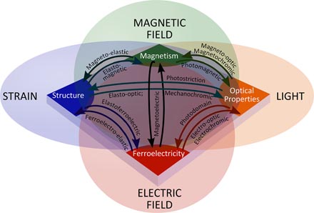
Figure 2. Conceptual sketch of possible couplings between the various functionalities of BiFeO3. We have taken some liberties in 'fashioning' some terminology.
Download figure:
Standard image High-resolution image2. Structural properties of epitaxial BiFeO3 films
The growth of high-quality epitaxial thin films on single-crystal substrates has opened up an extremely versatile method for modifying the crystal structure of materials. So-called strain engineering [34, 35] allows the application of many per cent of epitaxial strain to films, corresponding to stresses at which bulk compounds would fracture. The wide range of single-crystal perovskite substrates presently available commercially, as well as their various orientations and miscuts, enable strong control over the crystal structure of the grown film. While the bulk structure of BFO is rhombohedral (in space group R3c), when it is grown in thin films, epitaxial strain imposed by the substrate may cause the compound to take on a structure of reduced symmetry. Reports of tetragonal-like [36–41], rhombohedral [42–44], orthorhombic [45, 46], monoclinic MA [47–49], monoclinic MB [50, 51], and triclinic [52] BFO films can be found. This wide range of possible crystal structures highlights the strong effect that the substrate can have on the film's structural properties, and we shall see that these modifications may have substantial effects on the physical properties as well. Here we describe in detail the various symmetries of epitaxial BFO films: the bulk-like rhombohedral phase; the compressively-strained monoclinic MA phase; the highly-distorted tetragonal-like monoclinic phase for strong compressive strain, and finally the tensile-strained monoclinic MB and orthorhombic phases. In figure 3 the various crystal symmetries are summarized and are shown relative to the primitive pseudocubic perovskite unit cell. For each of the structures, we also describe how strain relaxation causes changes in symmetry, as well as to the domain structure.
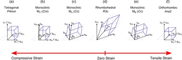
Figure 3. Summary of the various crystal structures that BFO forms in thin films. (a) Tetragonal BFO, only for very thin films; (b) the highly-distorted T-like monoclinic Cm phase, for strong compressive strain; (c) the MA monoclinic phase, for moderate compressive strain; (d) the bulk-like rhombohedral phase that forms on (1 1 1)-oriented substrates; (e) the MB monoclinic phase that forms at moderate tensile strain; and (f) the orthorhombic phase that can be stabilized by moderate tensile strain. The unit cells are shown relative to the primitive pseudocubic perovskite unit cell (light grey).
Download figure:
Standard image High-resolution image2.1. Structure and strain relaxation at moderate strain levels
On (1 1 1)-oriented cubic substrates (for example SrTiO3–STO), rhombohedral 'bulk-like' BFO is typically obtained (figure 3(d)) [43, 53–56], consistent with predictions of thermodynamic calculations [57]. Even for very small thicknesses (e.g. 20 nm) the film begins to relax and its lattice parameters approach their bulk values [43, 58]. Early reports of BFO films grown by liquid phase epitaxy (LPE) [42] or chemical solution deposition (CSD) [59] on (0 0 1)-oriented STO substrates evidenced a rhombohedral BFO symmetry, illustrating that the growth method, as well as substrate properties, can influence the structure of the film. Interestingly, for (1 1 1)-oriented growth on a substrate imposing tensile strain, thermodynamic calculations suggest that the structure is monoclinic MB [57]; this has yet to be confirmed experimentally. A bulk-like rhombohedral phase has also been reported for thicker films of 500 nm on (0 0 1) (LaAlO3)0.3(Sr2AlTaO6)0.7 (LSAT) [60] and very thick films (2 µm) on (0 0 1) STO [41].
The vast majority of studies of BFO epitaxial thin films are conducted using STO (0 0 1) substrates, which impart a compressive strain to the film. Another common substrate choice is orthorhombic DyScO3 (DSO), with the (1 1 0)o crystallographic orientation forming a (0 0 1)pc surface suitable for BFO growth. These substrates are chosen for their close lattice match to BFO, as well as to the commonly-used bottom electrode strontium ruthenate (SrRuO3; SRO). On such substrates in a (0 0 1)pc orientation, BFO typically grows with a monoclinic MA structure, see figure 3(c) [47–49, 51, 61–63], and reciprocal space mapping [64] around (1 0 3), (0 1 3) and (1 1 3) families of reflections can be used to confirm this structure, as shown in figure 4(b) [41, 47, 48]. In this monoclinic phase, the unit cell is doubled in volume and rotated by 45° with respect to the pseudocubic cell (see figure 3(c)). The (0 1 1) substrate orientation yields a monoclinic MB structure under compressive strain [51, 65], or an MA structure in tensile strain3 [65]. More exotic orientations of STO—such as (1 0 3), or (2 0 3)—give rise to a triclinic structure; this structure acts as the transitional bridge between the MA (STO 0 0 1) and MB (STO 1 1 0) symmetries [52].
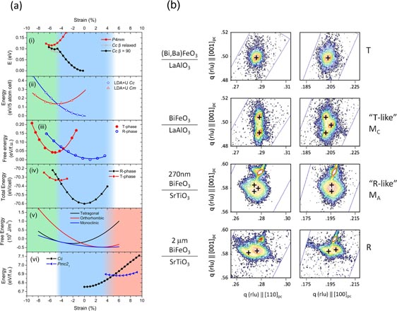
Figure 4. (a) Energy versus strain from various calculations, showing strain stability regions for different BFO structures. The sources of these data are (i) [95]; (ii) [91]; (iii) [100]; (iv) [96]; (v) [118]; (vi) [120]. The blue region corresponds to the stability region of the R-like phase, the green to the T-like phase, and the pink the orthorhombic phase. (b) X-ray reciprocal space mapping (RSM) around the 113 (left) and 103 (right) peaks of various BFO films. From top to bottom: tetragonal, monoclinic MC, monoclinic MA, rhombohedral R3c. These structures correspond to the sketches in figures 3(a)–(d), respectively. Reprinted with permission from [41]. Copyright 2011 American Physical Society.
Download figure:
Standard image High-resolution imageThere is evidence that ultrathin films (<10 nm) of BFO on STO (0 0 1) may be purely tetragonal [63, 66, 67]; this true tetragonal phase coincides with a suppression of octahedral tilting [68], imposed by the cubic substrate [67]. However, for typical thicknesses of 15 nm and above, monoclinic BFO is usually obtained. As the thickness is increased above about 30–90 nm [61, 66, 69–72] the BFO begins to relax via misfit dislocations and/or defects (such as oxygen vacancies) [73], and the out-of-plane lattice parameter approaches its bulk value. Experiments have routinely shown that BFO tolerates a wide range of strains: R-like BFO can be grown for strains −2.6% to +1.2% up to thicknesses of 60–70 nm without structural relaxation [60, 74, 75]. This characteristic may be related to the oxygen octahedra and their 'willingness' to rotate or tilt to accommodate strain [76, 77]. The rare-earth scandate substrates [78] such as DSO, TbScO3 (TSO), GdScO3 (GSO), SmScO3 (SSO), NdScO3 (NSO), and PrScO3 (PSO) [79], can all be used to grow coherently-strained films with either MA or MB structure [50, 74–76, 80–82]. On substrates that impose a lower misfit strain—such as DSO—films up to 300 nm may be fully strained [71]. Furthermore, lower electrode properties can help to maintain strain coherency up to larger thicknesses; e.g. on SRO-coated STO substrates, Holcomb et al [83] were able to grow strained BFO films up to 200 nm thick.
The inhomogeneities of the strain-relaxation process can be probed by x-ray microdiffraction [84], and it has been shown that different regions of the film may show different relaxation rotation, as well as different ferroelectric variants [84, 85]. The step-bunching growth mode can induce tilt in the crystallographic planes of BFO when grown on vicinal STO substrates [86]. Substrate orientation also affects the strain relaxation process. A detailed study by Kan et al [58] showed that for BFO films on (1 1 1)-oriented STO substrates, the out-of-plane lattice parameter relaxed towards its bulk value for thicknesses above 50 nm, while for (0 0 1)-oriented films, the out-of-plane parameter exhibits a much slower relaxation, and even at thicknesses greater than 500 nm the bulk parameter is not yet reached.
In addition to a change in the atomic structure, the strain relaxation process influences the domain structure of the films, with certain domain variants being favoured as thickness increases [63]. Lower electrodes (e.g. SRO) also play an integral role in lattice relaxation [84, 87], and in ferroelastic domain structure [88]. For instance, step-flow SRO gives BFO that has two domain variants, while step-bunch SRO gives four-domain-variant BFO. We will describe the domain structures in more detail in section 3.1.
2.2. High compressive strain: the T-like phase with large tetragonality
For large compressive strains (of more than about 4.5% in the (0 0 1) orientation), an epitaxially-stabilized polymorph of BFO can be formed. This polymorph is quite unique because it does not exist in the bulk (the reason for which is discussed in [89]), has a large tetragonality, with c/a ≈ 1.25–1.3, and vastly different physical properties. Early first-principles calculations alluded to a giant polarization of around 150 µC cm−2 for BFO in a highly-distorted tetragonal P4 mm phase [90], and experimental work by Rincinschi et al suggested that this polarization is indeed accessible in thin films [36]. This first experimental report used, however, non-epitaxial films, and it was not until 2009 that reports appeared of epitaxial films of BFO grown on LaAlO3 (LAO) substrates in the 'T-like' phase [37]. Initially thought to be a true tetragonal P4mm structure (figure 3(a)), this form of BFO was shown to be in fact monoclinic [37, 40, 41, 76, 91–94]. There is still some controversy regarding to which space group this structure should belong; for example, in [92] it is argued to be Cc, while some studies allude to the possible coexistence of Cm and Cc phases [37, 91], and others promote the space group Cm (figure 3(b)) [40, 76, 93, 94], where the monoclinic distortion is along the [1 0 0] direction.
The transition from R-like to T-like was initially thought to be isosymmetric [91, 95, 96], that is, in the same space group (namely Cc), but further experimental characterization [41, 76, 97] showed that the transition is in fact from MA to MC, in space groups Cc and Cm respectively. This was also consistent with other reported structural data [91]. The similarity of the free energies of the R-like and T-like structures at around 4–5% strain [41, 95, 98–100] (see figure 4(a)) gives rise to mixed phase films of BFO, with a distinctive surface morphology [38, 76, 101–103]. This stripe-like topography—comprised of R-like striped phases in the smooth T-like matrix [38]—observed in these mixed-phase films arises from the lattice mismatch between the R-like and T-like phases [101, 104], not unlike the ferroelastic domain walls that appear in many ferroelectrics, and in the R-like phase of BFO. The evolution of the c/a ratio in these domain walls is peculiar, since it is very gradual, over a 10–20-unit cell length [38].
In these mixed R-like/T-like specimens, a third polymorph of BFO, distinct from both the R-like and T-like phases, commonly appears [99, 101, 105, 106]. The crystal structure of this 'intermediate phase' is either monoclinic [101] or triclinic [105], with lattice parameters of about a = 3.81–3.82 Å and c = 4.15–4.18 Å, and often a tilt of the c axis of around 3° from the film normal [101]. It has been proposed that this third phase (sometimes called Tri-1 [105], MI [99, 101], or S' [106]) exists to fulfil lattice matching conditions of two adjacent regions composed of different R and T phases. This intermediate state indeed appears to play a crucial role in the enhanced piezoelectric response of these mixed-phase films, which we discuss in section 3.4.
Strain relaxation in T-like films usually occurs in a pure T-like phase → mixed T–R phase → R-like phase progression [107]. Very thin films on LAO, for example, can be pure T-like phase, while thicker films tend to be almost pure R-like phase. This is a standard strain accommodation/relaxation process in these films, whereby at larger thicknesses the elastic stress is relieved by the formation of the more stable R-like BFO. The surface morphology is accordingly modified, with T-like regions progressively suppressed with increasing thickness [107].
A temperature-driven phase transition with evolution from monoclinic MC → monoclinic MA → true tetragonal was reported for 60 nm BFO films deposited on YAO [108], and later on LAO, with the transition temperature at about 100–150 °C [93, 99, 106, 109, 110]. In this transition, the unit cell goes from primitive MC to a rotated and doubled MA unit cell then to a primitive tetragonal cell—a point which has implications for the ferroelectric polarization. Interestingly, the first part of this transition (MC → MA) is also observed in R-like films [48] at around 750 °C.
Growth conditions play a strong role in the stabilization of T-like BFO [111], and more specifically, whether R-like, T-like, or a mixture of these phases appears. For instance, pure T-like films can be obtained on STO substrates with a nominal strain of only −1.4% [112–114], by controlling growth rate and/or substrate temperature, while on NdGaO3 (NGO) substrates with strains of around 2.8%, R-like films have been grown [76, 82]. On LAO, by a careful fine-tuning of the growth conditions, almost phase-pure R-like BFO orT-like BFO can be grown [115]. This overlapping of the phase diagram highlights the fact that the many growth parameters, as well as epitaxial strain imposed by the substrate, all can be used as control parameters to tailor the structure of BFO films. As an even more dramatic example of this point, recently the T-like polymorph was stabilized in the (1 1 0) orientation by Liu et al [116]. Here the authors used LAO substrates with (1 1 0)-surfaces to form a monoclinic phase of BFO with a c/a of 1.2 and a polarization with sizeable components both in-plane and out-of-plane. This pioneering work on a non-conventional orientation of the T-like phase should lead towards epitaxial stabilization of the T-like phase with enhanced ferroelectric polarization in-plane—a feature that may be attractive for devices.
2.3. Tensile strain: MB and orthorhombic phases
We now move to the other end of the strain/structure phase space. As shown in figure 4(a), phase-field simulations and first-principles calculations predicted that at tensile strains of 2% and beyond, an orthorhombic phase (figure 3(f)) of BFO may be stabilized [45, 117–120]. In this phase, the polarization would lie in the in-plane 〈1 1 0〉 directions while the antiferromagnetic vector appears (mostly) out-of-plane. This phase was epitaxially stabilized for rather thin films of 15 nm by Yang et al [45]. It was shown by a combination of piezoresponse force microscopy (PFM) and second harmonic generation that the ferroelectric polarization of this phase lies in the plane (along 〈1 1 0〉pc), while x-ray absorption spectroscopy (XPS) showed that the antiferromagnetic vector lay 34° from the out-of-plane direction; a result consistent with that reported for other strongly tensile-strained films [75]. For films in the (−1 1 0) orientation, first-principles calculations suggest that an orthorhombic Pnma phase can be stabilized for compressive strain larger than about 1.6% [65, 121].
The various structures of BFO available to researchers afford a strong control of the ferroelectric properties, not least through the transition between the R-like and T-like phases, but the space in between as well. In the next section, we explore the ferroelectric and piezoelectric properties of BFO thin films. Before concluding this section, however, we would like to point out that there is a whole body of literature dealing with A and/or B site doping to dramatically modify BFO thin films' structure and physical properties—such as piezoelectricity, magnetism etc. Save for a few specific examples that we deem of particular illustrative and applicative importance, we do not discuss doping effects in this review. A more focused review of doping can be found in, for example, Yang et al [122].
3. Ferroelectric and piezoelectric properties
The initial excitement in BiFeO3 films was born as a result of the record ferroelectric polarization reported for thin films [123]. At that time, it was believed that bulk BFO had a very modest spontaneous polarization of 3.5–10 µC cm−2 [17]—an erroneous notion based on measurements of leaky, poor quality single crystals or ceramics. The giant polarization measured in thin films was initially thought to be the result of epitaxial strain playing a very strong role in enhancing this polarization [123]—an effect previously predicted for various ferroelectric perovskites [124] and observed in barium titanate (BaTiO3–BTO) [125]. For BFO, however, later reports on good quality, non-leaky single crystal samples also exhibited a large polarization [19, 20, 126], and first-principles calculations [90, 127] were consistent with these findings, indicating that this property is intrinsic to the material.
3.1. Ferroelectric domain structure
Since BFO's parent phase is rhombohedral, in films deposited on (0 0 1) substrates, the polarization can point along one of eight directions (figure 5(a)), giving rise to eight possible domain variants [128]. Accordingly, there are three possible types of boundaries separating the domain regions: 71°, 109° and 180° domain walls (DWs) (figure 5(a)). The latter is a purely ferroelectric DW, while the former two are also ferroelastic DWs (since there is a difference in spontaneous strain between the separate domain regions [129]). The various domain types can be imaged using PFM, and through a combination of in-plane (IP) and out-of-plane (OP) responses at various cantilever/crystal axis angles [130, 131], the full 3D domain structure can be established [132], as presented in figure 5(b). The intricate domain structure of BFO has engaged many workers to try to reach insight into, and deterministic control of, polarization switching [132–134] and the factors that affect it; for instance, polarization fatigue can be linked to ferroelastic domain population [135], and the film's crystallographic orientation can markedly alter domain switching characteristics [136].
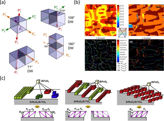
Figure 5. (a) Domain variants and simplistic view of domain walls in BFO. The polarization can point along any one of the eight body diagonals as indicated. Domain walls can be of three types depending on the relative polarization of the boundaries they separate: 109°; 180° or 71°. (b) Piezoresponse force microscopy images of BFO thin films. Using various scans with different cantilever angles, the domain structure (top) can be ascertained, and the type of domain walls (bottom) can be identified. Reprinted with permission from [310]. Copyright 2013 American Institute of Physics. (c) Domain engineering using miscut STO substrates (with SRO bottom electrode). With no miscut (left) the BFO grows with four polarization variants; with miscut along [1 0 0] (middle), two variants are obtained; and finally with a miscut along [1 1 0] (right), only one polarization variant is formed. Reproduced with permission from [311]. Copyright 2013 Elsevier.
Download figure:
Standard image High-resolution imageJudicious choice of substrate type, orientation, and/or vicinality can be exploited to control the morphology and type of pristine ferroelectric and/or ferroelastic domains in epitaxial BFO films [137]. The lower electrode can also play an important role. For example, using vicinal STO substrates with miscuts along particular high-symmetry crystallographic directions, the eight polarization variants of BFO can be reduced to four, two, or just one polarization variant, see figure 5(c) [72, 138–140]. Alternatively, anisotropic strain induced by orthorhombic substrates such as TbScO3 [80, 141] or DyScO3 [88, 142] can be used to preference particular domain patterns. The specific domain morphology can range from a fractal, mosaic like arrangement, to straight stripe-shaped domains [143, 144]. Finally, doping BFO with La can reduce its TC to below the growth temperature, providing another method to control domain morphology [145].
A rather curious attribute of BFO is that its ferroelectric domain walls can be conductive [8, 146–148]. Ferroelectric DW nanoelectronics has become an active area of research, striving to understand the physical origin of the walls' conductive properties, explore their other functionalities, and design and characterize domain wall-based devices. In addition, the domain walls may possess distinct magnetic properties. BFO domain walls will be covered in more detail in section 6.
3.2. Strain and polarization
Fully-saturated polarization hysteresis loops are routinely obtained on thin-film samples when the leakage is sufficiently low (see example in figure 6(a)). In (1 1 1)-oriented films, the total ferroelectric polarization can be measured in a capacitor geometry, and values close to 100 µC cm−2 have been reported [43, 149]. For films in other orientations—such as (0 0 1) or (1 1 0)—the measured polarization is the projection of the (1 1 1) polarization vector along the measurement direction [53, 138, 150, 151], as illustrated in figure 6(b). Measured spontaneous polarization values for epitaxial BFO films are around 90–120 µC cm−2 [43, 53, 61, 123, 152] along the [1 1 1]pc direction. The T-like phase of BFO is suggested to have an even larger polarization of ∼150 µC cm−2 [102], which would be a direct result of the larger cation shifts in this highly-distorted phase [153].
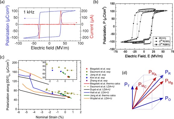
Figure 6. (a) Polarization hysteresis loop for BFO film grown on (1 1 1) STO substrate. Reprinted with permission from [43]. Copyright 2008 American Institute of Physics. (b) Polarization hysteresis loops for BFO grown on (0 0 1), (1 0 1) and (1 1 1) oriented STO substrates, showing that when normalized by their projection (30.5, 20.5 and 1 respectively) the polarization along [1 1 1] is ∼100 µC cm−2. Reprinted with permission from [53]. Copyright 2004 American Institute of Physics. (c) Strain dependence of polarization along [0 0 1] for R-like and T-like BFO. The experimental data are shown as symbols; while theoretical results are shown as lines. (Inset) the experimental data for the R-like phase on the same horizontal scale. The sources are: Biegalski et al [312]; Daumont et al [156]; Jang et al [158]; Kim et al [61]; Zhang et al [102]; Dupé et al [91]; Hatt et al [95]; and Wojdel et al [96]. (d) Polarization direction for BFO of various symmetries.
Download figure:
Standard image High-resolution imageThe dependence of ferroelectric properties on strain in BFO is very different from that of tetragonal ferroelectrics such as BaTiO3 [34]. In BFO, the two structural instabilities (cation displacement and antiferrodistortive rotations) coexist and compete [154]. As a result, strain-sensitive effects are more complex and cannot be extrapolated from the behaviour of other ferroelectric perovskites. As a notable example of the impact of these antagonistic degrees of freedom, the ferroelectric Curie transition temperature TC in BFO was shown to be strongly reduced with increasing compressive strain [74, 155]. This is contrary to what occurs in e.g. BaTiO3 [125]. First-principles calculations indicated that the cause of this phenomenon is the antiferrodistortive rotations, which have a stronger effect on TC than the polar distortion induced by strain [74].
The influence of strain on the ferroelectric polarization is much less pronounced. The total polarization along (1 1 1)pc does not show a strong strain dependence [156–159]; however, upon application of a biaxial strain in the (1 1 0) plane, the projection of the polarization onto the (0 0 1) direction changes considerably [61, 90, 156, 158]. This is the result of the rotation in the (1 1 0) plane of the polarization away from the 〈1 1 1〉 direction. Thermodynamic [57], first principles [90], and Landau-Devonshire [117, 159] calculations corroborate this trend of polarization change with strain, albeit with vastly different values of polarization and slope: the change of polarization varies between −4.7 µC/cm2/% strain [156] to −15.15 µC/cm2/% strain [158]. In figure 6(c) we gather many experimental and theoretical studies of the polarization with strain, where it can be seen that the general trend is an increase in the polarization along (0 0 1)pc with increasing compressive strain, consistent with a rotation of the polarization vector, and that the T-like phase exhibits a much larger spontaneous polarization.
The rotation of the polarization vector with strain observed in BFO is part of a larger structural O → MB → R → MA → T progression in ferroelectrics as described by Vanderbilt and Cohen [160]. As the symmetry changes with epitaxial strain, the polarization direction is also inherently modified. A portion of this rotation path (MA–triclinic–MC) is observed in bulk relaxor crystals under electric field [161–163]. The polarization rotation in BFO is consistent with observations that show that orthorhombic BFO has its polarization in the plane [45], the MB phase is rotated from [1 1 1] towards the [1 1 0] direction [50], the MA phase has a polarization rotated towards [0 0 1] [156, 158], and the T-like MC phase has its polarization slightly tilted away from the [0 0 1] direction in the (0 1 0) plane (see figure 6(d)). The strain-induced R → MA → MC → T transition (also seen in the 0.7Pb(Mg1/3Nb2/3)–0.3PbTiO3 system under electric field [164]) in BFO is elegantly illustrated by Christen et al [41], where the authors used a combination of epitaxial and chemical strain (i.e. doping) to induce the various phases, as shown in figure 4(b).
The weak effect of strain on the polarization of BFO in its R-like phase can be attributed to its relatively small piezoelectric coefficient [10, 165], which amounts to around 40–60 pm V−1 [132, 156, 166, 167] in unstrained films. We now discuss ways of improving the piezoelectric response, first by a composition-induced morphotropic phase boundary (MPB), and second by a strain-induced phase transition.
3.3. Morphotropic phase boundary and antiferroelectric state induced by rare earth doping
In ferroelectrics, the intimate link between crystal structure and the electromechanical response means that a compound that is compositionally-tuned between two different structures—that is, at a morphotropic phase boundary (MPB)—can exhibit a remarkably enhanced piezoelectric response [168, 169]. A classic example of this is Pb(ZrxTi1−x)O3 (PZT): this solid solution displays exceptional piezoelectric coefficients, hence its use in actuators, acoustic sensors, etc [170]. With current environmental concerns regarding the toxicity of lead, researchers have been actively investigating other lead-free oxide compounds and solid solutions thereof, for use in these important applications.
While BFO was considered early as a possible alternative to lead-based piezoelectrics, its electromechanical coefficients are not large enough to compete with more conventional ferroelectrics. To explore the possibility of a MPB in the BFO system [171], Fujino et al prepared rare-earth substituted BFO films by a combinatorial method (i.e. compositional spread samples) [166]. It was observed that for samarium-substituted BFO, a peculiar phase transition occurs at around 14% Sm composition. The out-of-plane lattice constant exhibits a drastic change, the dielectric constant rises to ∼400, and the d33 shows a dramatic increase up to over 100 pm V−1 at the transition (figure 7(a)) [166]. Concomitantly, the ferroelectric hysteresis loops of Sm-doped BFO change progressively from a standard ferroelectric shape for Sm composition <13%, through to a double hysteresis at Sm composition 14% and above [166] (shown in figure 7(c)). Detailed high-resolution transmission electron microscopy (HRTEM) studies [172] and first-principles calculations [173] revealed the origin of this enhanced response to be the formation of a nanoscale mixture of BFO-Sm with a different structure: while Sm-doped BFO with low doping (<14%) is rhombohedral (polar), Bi0.8Sm0.2FeO3 has an orthorhombic (non-polar) structure. Applying an electric field causes a structural transformation from the orthorhombic phase to the rhombohedral phase, i.e. causing domain boundary movement, giving rise to an enhanced electromechanical response [173].

Figure 7. (a) Measured d33 for Sm-substituted BFO thin films. At the MPB the d33 rises to a peak of ∼100 pm V−1. Reprinted with permission from [166]. Copyright 2008 American Institute of Physics. (b) Temperature-composition phase diagram for rare-earth substituted BFO thin films. At low RE composition, the structure is rhombohedral (left); while for higher RE composition, the structure is orthorhombic (right). Reprinted with permission from [173]. Copyright 2010 Wiley-VCH. (c) Polarization hysteresis loops for RE-substituted BFO thin films, showing that the control parameter is the average A-site ion radius. The composition is non-ferroelectric for rave < 1.348 Å. Reprinted with permission from [173]. Copyright 2010 Wiley-VCH.
Download figure:
Standard image High-resolution imageAdditional studies using other rare earth substitutions (Dy, Gd, and La) showed universal behaviour, with a morphotropic phase boundary and a corresponding enhancement in the dielectric constant and piezoelectric coefficient [173]. The control parameter was shown to be the average A-site ionic radius, and after scaling the results for different A-site cations to their average, the curves for dielectric constant, d33, and hysteresis curves (figure 7(c)), all collapse into one, confirming the universality of the behaviour. Importantly, it was shown that doping with La3+—a cation with the same nominal radius as Bi3+—did not cause the marked increase in the dielectric constant and electromechanical response [174, 175], indicating that the property enhancement is a direct consequence of the structural transitions induced by the chemical substitution of a smaller A-site cation. Deeper investigations with regard to temperature yielded the phase diagram shown in figure 7(b). Near room temperature, the transition between the rhombohedral and orthorhombic phases occurs through a phase boundary that exhibits antiferroelectric behaviour, while at higher temperatures this intermediate phase is suppressed [173].
In addition to the phase transition induced by the continuous Sm substitution, a rotation of the polarization vector is observed with increased Sm doping [176]. While the replacement of the Bi cations by Sm substitution causes a decrease in the absolute magnitude of polarization (since the ferroelectricity in BFO is primarily due to the lone pair electrons in Bi3+ [177, 178]), the out-of-plane component of PR remains almost constant until 13% Sm composition, since the polarization vector rotates towards the [0 0 1]pc direction. This conclusion was supported by additional data on Sm-substituted films on (1 1 0) and (1 1 1) oriented STO substrates, where it was observed that the measured polarization along the (0 0 1) direction was consistent with a rotation of the polarization direction [176]. Indeed, this rotation of the polarization vector probably plays an important role in the enhancement of the d33 at the MPB in this compound, just as it does in the relaxor-based systems [168].
3.4. Strain and piezoelectricity; strain-induced R-like to T-like phase transition
The piezoelectric response of BFO appears relatively sensitive to epitaxial strain [156]. This is particularly true of R-like BFO under compressive strain, for the proximity to the R-like/T-like transition at around 4–5% strain, causes a divergence of the piezoelectric coefficient d33 [96]. However, as described in section 2.3, at these strain levels BFO films form in a mixed phase where both the R-like and T-like polymorphs appear. These mixed phases have been shown to have strongly enhanced piezoelectric response [38], with electric field-induced strains of the order of 2%. In fact, BFO at the boundary between these two phases can offer a piezoelectric response almost four times higher than the widely-used piezoelectric material PZT [179]. Since BFO is lead-free, these results created a stir in the community, for lead-free piezoelectrics are highly sought after [180].
The microscopic origin of the enhanced piezoelectric response has been elucidated to be a movement of the phase boundaries between the different phases [105, 181], with the third 'intermediate' polymorph playing an important role in the transformation, since it is the bridging phase between them [106]. The control of the relative ratios of R-like and T-like phases is important for potential device applications, as the R-like regions in the films tend to control the electromechanical response, and PFM-based techniques have proven very useful [182], through which regions of R-like and T-like BFO can be created at will.
The piezoelectric response also appears to be enhanced through a temperature-driven MC → MA phase transition that occurs at around 150 °C in mixed-phase films [99]. At this transition, the d33 increases from about 60 pm V−1 up to about 100 pm V−1, which arises from the additional degrees of freedom in the lattice structure and the polarization and the fact that they can respond to an external electric field more strongly [99]. The expected polarization rotation from [x 0 z] at low temperature to [x x z] at high temperature was also observed.
The enhancement in piezoelectric response may not be limited to simply the R-like/T-like transition. There has been speculation [118] that the transition between the monoclinic MB and orthorhombic phases that occurs at moderate tensile strain may uncover a bridging phase with a piezoelectric response even stronger than the R/T transition. Very recently a mixed rhombohedral/orthorhombic phase was explored [46] for films grown on GSO substrates; however, no enhancement of piezoelectricity was reported at the phase boundary.
It should be noted that while both the substitution-induced and strain-induced MPBs are highly interesting from a physical point of view, their use in devices is limited since the absolute strains induced in thin films are very small. The most likely envisageable application would be in nano-devices. In actuators, bulk crystals are used since their strains can be many orders of magnitude larger.
4. Magnetic properties
In the bulk, BFO displays a cycloidal order [15, 183, 184] with the spins in each (1 1 1) plane modulated along one of the three possible
![$[1\,\bar{1}\,0]$](https://content.cld.iop.org/journals/0953-8984/26/47/473201/revision1/cm503050ieqn001.gif) directions [185]. The cycloid has a period of about 62 nm [15], and is essentially harmonic [183, 186]. Recent small angle neutron scattering (SANS) experiments showed that the spins actually also cant away from the rotation plane by up to about one degree [187]. In addition, the spins are antiferromagnetically coupled in the (1 1 1) direction, so that each magnetic domain consists of antiferromagnetically coupled (1 1 1) planes of cycloidally-modulated spins. This cycloidal state can be destroyed by the application of a large magnetic field of about 18 T [188, 189], or by chemical substitution (rare earths for Bi [190, 191], Mn for Fe [192, 193]). Then, a weak-ferromagnet state forms, with a remanent magnetization on the order of 0.01 μB/Fe. The Néel temperature of bulk BFO is about 640 K [14].
directions [185]. The cycloid has a period of about 62 nm [15], and is essentially harmonic [183, 186]. Recent small angle neutron scattering (SANS) experiments showed that the spins actually also cant away from the rotation plane by up to about one degree [187]. In addition, the spins are antiferromagnetically coupled in the (1 1 1) direction, so that each magnetic domain consists of antiferromagnetically coupled (1 1 1) planes of cycloidally-modulated spins. This cycloidal state can be destroyed by the application of a large magnetic field of about 18 T [188, 189], or by chemical substitution (rare earths for Bi [190, 191], Mn for Fe [192, 193]). Then, a weak-ferromagnet state forms, with a remanent magnetization on the order of 0.01 μB/Fe. The Néel temperature of bulk BFO is about 640 K [14].
In early experimental reports on R-like BFO thin films, the destruction of the cycloidal structure and the possible releasing of the weak ferromagnetic moment were discussed [54, 123]. Typical films have a thickness comparable to the period of the cycloidal spin modulation, which causes one to ponder the influence of dimension reduction on the cycloid state. Epitaxial strain, causing additional anisotropy terms of elastic origin, was also pointed out as a possible destabilizing factor [54]. Experimentally, detecting the presence of the cycloid is not an easy task. Using neutron diffraction in thick, largely relaxed BFO films on miscut STO(0 0 1) substrates, Ke et al [194] and Ratcliffe et al [195] detected split [1/2 1/2 1/2]-type peaks characteristic of the bulk-like cycloidal order with a period of ∼62 nm (see figures 8(a)–(b)). A few years earlier, in thinner, strained films, Béa et al observed a single peak, corresponding to a pseudo-collinear G-type antiferromagnetic state [70]. To distinguish between the influence of strain and that of thickness reduction, a systematic study of the magnetic order in ∼70 nm thick fully strained films grown on various substrates was performed by Sando et al [75]. Using conversion electron Mössbauer spectroscopy [196] in ∼100% 57Fe-enriched films, they found that virtually unstrained films (grown on GdScO3) display asymmetric spectra typical of the bulk cycloid, while strongly strained films (both tensile and compressive) have symmetric spectra indicative of pseudocollinear antiferromagnetism (figure 8(c)). At weak tensile strain, they also revealed a new cycloidal order (absent in the bulk) with a different propagation direction. Comparison with phase diagrams calculated from Landau–Ginzburg theory showed that magnetoelastic anistropy destabilizes the cycloid at large strain. Interestingly, both data and theory also indicate that the spins tend to lie in the film plane at large compressive strain, and out of the plane at large tensile strain.
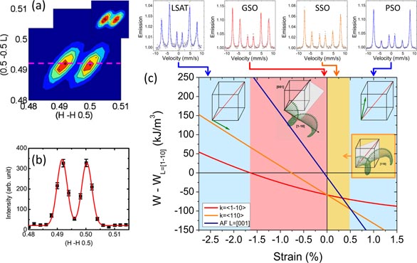
Figure 8. (a), (b) Results of neutron diffraction on thick, partially-relaxed BFO films, evidencing the presence of the cycloidal modulation. Reprinted with permission from [194]. Copyright 2011 American Physical Society. (c) Top: conversion-electron Mössbauer spectroscopy spectra for BFO thin films in various strain states. Bottom: free energy of the system relative to a pseudo-collinear order, showing the stability regions for a number of cycloidal orders. Blue regions correspond to pseudo-collinear order; pink region to the bulk-like cycloid, and the yellow region to the new type-2 cycloid. Reprinted with permission from [75].
Download figure:
Standard image High-resolution imageIn strained films not displaying a cycloidal order, a weak ferromagnetic moment is expected, and is generally observed [54, 56, 197, 198]. Very large values have sometimes been reported and ascribed to strain effects [44, 123], magnetism at domain walls [199, 200] or interface effects [201]. While all these mechanisms may contribute to an enhancement of the weak moment from its expected value of around 0.01 μB/Fe, it is likely that values well in excess of 0.1 µB/Fe have an extrinsic origin, as pointed out by Béa et al [202]. In the R-like phase, the Néel temperature has been measured by various techniques (x-ray linear dichroism [203], x-ray diffraction [74], neutron diffraction [74, 204] and Mössbauer spectroscopy [74, 75, 205]) and is found to be close to the bulk value (640 K), with a weak strain dependence [74] (see the phase diagram in figure 9).

Figure 9. Temperature-strain phase diagram for BFO thin films for both the R-like and T-like phases, showing magnetic and ferroelectric transition temperatures, from various experimental and theoretical studies. These data are from [74, 106, 204, 205, 208, 313]. Dashed lines indicate hypothetical phase transition temperatures in unexplored regions of the diagram. Transition lines between different magnetic orders are represented vertically for simplicity; further research is required to ascertain their exact positions.
Download figure:
Standard image High-resolution imageThe magnetic order in the T-like phase is more controversial, with reports of a pure G-type order at 300 K [37], as well as of mixed C- and G-type orders [206], with different temperature dependencies. In independent studies, the Néel point was determined as ∼370 K from Mössbauer spectroscopy [205] and x-ray linear dichroism [207], but only 320 K by neutron diffraction [206]. Clarifying this issue is particularly relevant because a coupled structural-ferroelectric phase transition occurs near 370 K [93, 109, 205, 207], which has been argued to be coupled to the Néel transition as well [205, 207]. Complementary experiments using different techniques on the same samples should be performed. We note that various T-like structural phases are almost degenerate in energy [41, 91, 95, 98] and may have different magnetic properties. For instance, Escorihuela et al predict C-type order below an in-plane parameter of 3.78 Å, a G-type order above, and a two-dimensional spin order at the phase boundary [208].
5. Optical properties
BiFeO3 is a semiconductor with a moderate room-temperature band gap in the visible range—around 2.6–3.0 eV [209–213], which is considerably lower than most other ABO3 perovskites (LiNbO3, BaTiO3 etc) [31]. The band gap is calculated to be indirect; however most experiments evidence a direct gap, which may be a result of the rather flat valence band [214].
A convenient and straightforward method for measuring the optical properties of BFO thin films is spectroscopic ellipsometry [215]. Using this technique, the complex refractive index can easily be determined over a wide wavelength range (see figure 10) and from this the optical band gap can be extracted by generating a Tauc plot of (αE)2 versus E where α is the absorption and E is the photon energy. Transmission spectroscopy is also a useful technique, and can serve as a good method for cross-checking the accuracy of ellipsometry measurements [209, 216]. The imaginary part of the dielectric function of BFO is dominated by a number of charge transfer transitions (CTTs) [217, 218], which are related mostly to O 2p → Fe 3d transitions. Their energies are typically found to be at around 2.5, 3.2, 4.5 eV [209, 210, 219, 220]. Some works also report transitions at energies above 6 eV; these may be attributed to higher Bi 6s transitions [213]. The transition at around 2.5 eV, as well as another at 2.2 eV [219, 221, 222], have been said to be related to oxygen vacancies [212, 219]; however these are probably intrinsic transitions related to a low-lying t1g(π) → t2g CTT which is common in ferrites with octahedral FeO6 centres [218].
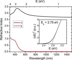
Figure 10. Complex dispersion law of a BFO thin film. (Inset) Tauc plot for a BFO thin film, with extrapolation to (αE)2 = 0 yielding a direct gap of ∼2.75 eV.
Download figure:
Standard image High-resolution imageAs shown in figure 10, the complex refractive index of BFO thin films shows a real part that is quite high for ferroelectrics, while the imaginary part is negligible for wavelengths above ∼600 nm, indicating that absorption is very low in the IR region. The latter characteristic has stimulated work on applications of BFO in telecommunications devices, such as modulators [209]. BFO films are highly birefringent [223], just as in the bulk [32, 33]. The strong birefringence in BFO may help it find application in optical or plasmonic modulators; we discuss this further in section 6.
Like a number of other non-centrosymmetric materials, BFO exhibits a bulk photovoltaic (BPV) effect. This means that light-induced charge carriers are driven by the intrinsic electric field caused by the non-centrosymmetry of the crystal lattice, and can thereby give rise to photovoltages much larger than the band gap. In thin films, initially this effect was thought to be a purely domain-wall phenomenon [224, 225]; however bulk BFO exhibits the BVP effect [30], first-principles calculations predict it [226], and subsequent experimental reports showed that the BPV effect indeed is present in thin films [141, 142, 227]. The domain wall and bulk phenomena appear to be quite different, and the growth method of the films probably plays a considerable role in determining which phenomenon dominates. While the BVP is interesting from a physical point of view, unfortunately the photocurrents obtained are much too low to be of practical interest for light harvesting applications. A critical limitation is the very low carrier mobility in BFO. The BVP can however be utilized in data storage devices, as discussed later.
The optical properties of BFO films appear to be only moderately responsive to external perturbations such as strain, electric field, magnetic field, etc. While the non-linear optical coefficients are quite high [210], particularly in the T-like phase [228], the linear electro-optic (EO) (Pockels) coefficients are modest at around 10 pm V−1 [223]. That said, the effectiveEO coefficient (which would be the figure-of-merit for a modulator device) is still sizeable, and amounts to around half that of the most widely used optical modulator medium, LiNbO3. Even more promising is that the T-like phase may show greater potential in that respect, since DFT calculations suggest that some coefficients could be up to 50 pm V−1 [223].
Existing reports point to a weak strain dependence of the optical properties. Films grown on STO (0 0 1), STO (1 1 1), and LSAT substrates evidence a relatively unchanged band gap at 2.77 ± 0.04 eV [210]. A separate report showed a 50 meV difference in the gap for films deposited on STO and DSO substrates [220]. It is likely that there should be a systematic dependence of the band gap on misfit strain (since it has been predicted in octahedral-rotation perovskites [229]); however a study of the optical gap on various substrates [82] surprisingly yielded no clear dependence of the gap on strain. A very recent paper theoretically exploring the effect of tensile strain on BFO epitaxial films predicted that the band gap should increase (albeit slightly) with tensile strain [230]. The T-like phase of BFO has a much larger band gap at ∼3.1 eV [82, 216, 231] (figure 11), presumably due to either the lowering of energy of the valence O 2p orbitals, or the raising of the conduction Fe 3d orbitals [216, 231]. A more detailed experimental study on the dependence of the optical properties with strain is required.
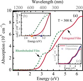
Figure 11. Absorption of R-like and T-like BFO films, clearly showing that the T-like phase has an onset of absorption at higher energy than the R-like phase. Inset, top left: Tauc plot showing that the T-like phase has an optical band gap at ∼3.1 eV. Inset, bottom right: transmission spectroscopy and spectroscopic ellipsometry results yield good agreement for absorption coefficient. Reprinted with permission from [216]. Copyright 2010 American Institute of Physics.
Download figure:
Standard image High-resolution imageIn the R-like phase, weak spin-lattice coupling has been evidenced at the Néel temperature, through Raman spectroscopy [232–234], and a softening of the band gap [82, 219, 235]. In the T-like phase, the gap may evidence a transition at 380 K [82]; this would be consistent with the Néel temperature being at this point [205].
Finally, chromic phenomena have been reported in BFO; that is, changes in light absorption under the application of an external stimuli such as magnetic field (magnetochromism [236]) or electric field (electrochromism), in the latter case in Ca-doped BFO thin films [237].
6. Devices based on epitaxial BiFeO3
The multifunctional character of BFO offers opportunities to design a wide variety of devices exploiting a single functionality (ferroelectricity, piezoelectric response, birefringence, etc) or the synergy between multiple functionalities (through e.g. the magnetoelectric effect). In the following we review BFO-based devices for electronics, spintronics, and photonics.
6.1. For electronics
Most electronic devices based on BFO thin films exploit its very large polarization. They can operate in either a planar geometry (such as ferroelectric field-effect transistors—FeFETs) or a perpendicular geometry (ferroelectric diodes or ferroelectric tunnel junctions [238]). In the former case, the current flows in a conductive channel adjacent to the ferroelectric, while in the latter, the current flows across the ferroelectric (in different transport regimes [239, 240] including direct tunnelling, Fowler-Nordheim tunnelling, field emission, etc). Another family of devices utilize the transport properties of domain walls in BFO. This emerging field of ferroic domain wall nanoelectronics [241] is very young and many issues remain unresolved, as we will discuss.
To achieve the largest possible modulation of the channel resistance in FeFETs, the transport response of the channel material must be very sensitive to changes in the carrier density, and the ferroelectric must allow for a large carrier density modulation [242]. Nominally, the density of surface charge accumulated or depleted by the ferroelectric is equal to the polarization. If strongly correlated oxides are used as the channel, functional properties dependent on carrier density (such as magnetic order, as occurs in mixed valence manganites [243]) may also be controlled by switching the ferroelectric polarization direction. This type of device—combining correlated oxides and ferroelectrics—is central to Mottronics, a flavour of oxide electronics specifically aimed at the electrical control of strong correlations. The large polarization of BFO makes it an attractive gate oxide in FeFETs (P = 100 µC cm−2 corresponds to ns = 6.25 × 10¹⁴ electrons per cm2; for a typical perovskite oxide channel with an in-plane lattice constant of 3.8 Å this is 0.9 electrons per surface unit cell). Another advantage of BFO is that it can accommodate a broad range of lattice mismatches with underlying channel materials that can then be combined with R-like or T-like BFO.
CaMnO3 is a Mott insulator in which a few per cent of Ce doping (being 4+, each Ce ion contributes two electrons) induces a transition to a metallic state [244, 245]. CaMnO3 thus appears an attractive channel material for FeFETs. CaMnO3 has a smaller lattice constant and is thus only compatible with T-like BFO. As visible in figure 12(a), the resistivity is indeed strongly modulated by the accumulation or depletion of charge in the channel [246]. The OFF/ON ratio reaches 10 at 200 K. Surprisingly, the OFF/ON ratio does not increase further if the channel thickness is decreased below ∼20 unit cells, likely due to dead layer effects. In these experiments, the maximum sheet carrier density modulation was Δns = 0.6 × 1014 cm−2 (corresponding to ΔP = 11 µC cm−2). This is within the range of previously-reported values [247, 248] but more than one order of magnitude lower than the nominal value expected from the polarization of T-like BFO. FeFETs combining R-like BFO and LSMO channels have also been investigated [249, 250], where the maximum channel resistance changes by a factor of ∼3 at low temperature [250]. No information on the carrier density modulation was provided in these studies. Interestingly, the field effect from BFO also influences the magnetic properties of the manganites, as we will discuss later.

Figure 12. Summary of results and performance of FeFET devices. (a) Schematic of device. (b) Optimal micrograph of device; piezoforce response microscopy out-of-plane phase images and sketches showing the two domain states. (c) Modulation of resistivity in an FeFET device using a CaMnO3 channel and T-like BFO as the gate. (d) Modulation of the superconducting transition temperature in a FeFET using an YBCO channel and R-phase BFO as the gate. (a), (d) Reprinted with permission from [308]. Copyright 2011 American Physical Society. (b), (c) Reprinted with permission from [246].
Download figure:
Standard image High-resolution imageIn FeFETs combining R-like BFO and an ultrathin superconducting YBa2Cu3O7−δ (YBCO) channel, a large change of the transport response of the channel was also measured. In cuprates, the superconducting critical temperature (Tsupra) strongly depends on carrier concentration and in this YBCO/BFO FeFET a modulation of Tsupra of 30 K (produced by a Δns = 1.8 × 1014 cm−2, corresponding to about ΔP = 30 µC cm−2) was found (figure 12(b)). This is at least a factor of four larger than previous reports using other ferroelectrics (notably PZT) [251].
Charge transport modulated by polarization direction was also reported in perpendicular-geometry devices such as diodes and tunnel junctions. Figure 13(a) reproduces the results of Choi et al on Ag/BFO/Ag structures [30]. Current versus voltage—I(V)—characteristics measured across the device are strongly asymmetric, as occurs in p–n junction diodes. Interestingly, the sign of the asymmetry reverses as the polarization direction of BFO is switched. These particular results were on BFO crystals, but similar results have been reported in thin film heterostructures [252–255]. Practically, the device resistance is strongly dependent on the direction of the ferroelectric polarization, and resistive switching ratios in excess of 102 have been reported [253, 255]. The precise mechanisms responsible for the effect are still debated (bulk-driven, associated with charge accumulation/depletion and band bending [256]; or interface driven, with local defects such as oxygen [255] or bismuth [254] vacancies playing a major role [257]). These ferroelectric diodes also exhibit the bulk photovoltaic effect, which will be discussed further in section 6.3.
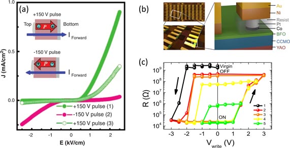
Figure 13. (a) Diode effect in BiFeO3 single crystal as evidenced by J-E curves. The direction of the ferroelectric polarization determines the polarity of the diode effect. Reprinted with permission from [30]. Copyright 2009 AAAS Publishing. (b) Illustration of an array of 50 fully patterned ferroelectric tunnel junctions. Reprinted with permission from [270]. Copyright 2014 American Institute of Physics. (c) Typical hysteresis curves of resistance with applied voltage of a 180 nm wide Pt/Co/BFO/CCMO capacitor using T-like BFO. Cycle 1 shows the first switching from the virgin state to the ON state. Cycles 2 and 3 show reproducible hysteresis from the ON to the OFF state. Cycles 4 and 5 represent minor loops with intermediate resistance states. Reprinted with permission from [264]. Copyright 2013 American Chemical Society.
Download figure:
Standard image High-resolution imageIn BFO-based capacitor structures, when the BFO thickness is reduced to just a few nanometres, quantum mechanical tunnelling of charge carriers becomes possible and, at very low thickness and bias voltage, dominates the transport response. Just as polarization charges can produce band bending at ferroelectric/metal interfaces, the intrinsic potential profile of a tunnel barrier is strongly modified if the barrier material is ferroelectric. Polarization charges are screened in the electrode over a finite thickness (ranging from one ångström in very good metals to a few nm and higher in poor metals and semiconductors) and this imperfect screening generates a (positive or negative) potential that adds to the intrinsic screening. With dissimilar electrodes, the resulting potential profile is strongly asymmetric; the sign of this asymmetry depends on the ferroelectric polarization direction, as does the average barrier height. Because tunnel transmission depends exponentially on the barrier height, polarization switching produces tunnel resistance switching [258, 259]. The first clear demonstration of a giant electroresistance effect (∼1000 at room temperature) produced by polarization switching in FTJs was provided by Garcia et al [260], and quickly confirmed by other groups [261, 262]. With BFO tunnel barriers, a few results have been reported. With 3 nm thick R-like BFO barriers, Hambe et al found a modest electroresistance of only 80% at low temperature [263]. In contrast, a very large effect (>104) was measured at 300 K by Yamada et al (see figure 13(c)) [264], and resistance switching was clearly correlated to polarization switching. In addition, these BFO-FTJs behave as memristors [265, 266] in which the device resistance is not determined by voltage-controlled defect distributions (as in many memristive systems [267], including some based on thick BFO layers [268]), but by the ferroelectric domain configuration in the barrier [269]. Very recently, systematic tests revealed a good reproducibility for BFO-based ferroelectric memristors, with an endurance of 4 × 10⁶ cycles [270].
The discovery of finite conductivity at domain walls in BFO has triggered a flurry of activity in the scientific community working on BFO, multiferroics, and ferroelectrics in general. In the initial report by Seidel et al [8], only 109° and 180° DWs were found to be conductive, but not 71° DWs. This was consistent with theoretical calculations indicating that the band gap decreases in the vicinity of the boundary [8], arising from the step in electrostatic potential related to the change in polarization direction. A subsequent report however showed that conduction also occurs in 71° DWs [146]. This sparked controversy regarding the mechanism giving rise to conduction, i.e. intrinsic (band gap reduction, as argued in [8] and subsequently in [200, 271]) or extrinsic (oxygen vacancies being generated at or attracted to the wall, allowing conduction, as argued in [146], and in [272] on the basis of first-principles calculations indicating essentially no change of the electronic structure at the DW, for all three types). In a later paper, Seidel et al also showed that DW conductivity in La-doped BFO films can be controlled by oxygen vacancies [148], pointing at a dominant role of extrinsic factors in determining the electronic response of DW in BFO. We note that following these results, DW conductivity was also found in other ferroelectrics such as PZT [273], BaTiO3 [274], LiNbO3 [275], and rare earth manganites [276].
Since the field is in its infancy, very few device prototypes have been realized [277]. One is presented in figure 14, showing how transport between two electrodes separated by a BFO element can be modulated by writing and erasing DWs. Another interesting result is from Maksymovytch et al who found a memristive behaviour of conductive DWs in BFO characterized by scanning probe experiments [147].
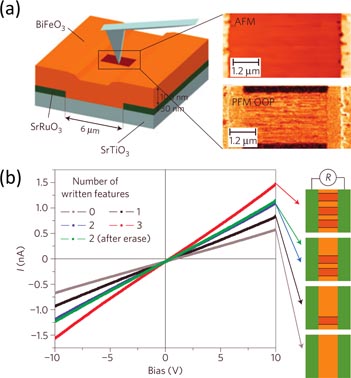
Figure 14. (a) Device utilizing conductive domain walls in BFO. A scanning probe is used to create and erase domain wall features; the I–V curves show that the current can be controlled by the number of domain walls present between the electrodes. Reprinted with permission from [8]. Copyright 2009 Nature Publishing Group.
Download figure:
Standard image High-resolution image6.2. For spintronics
The concomitance of ferroelectricity and magnetic order at room temperature makes BFO an obvious candidate for applications in the field of spintronics. In particular, the magnetoelectric coupling between the two orders opens the way to the control of magnetic properties by an electric field, and thus to energy-efficient spintronic devices in which information is stored magnetically and written electrically. The prototypical example of such devices is a magnetic random access memory (MRAM) with an electrical writing procedure (MERAM) [6, 278, 279].
In BFO, the spins are rigidly coupled to the crystal lattice, and 71° or 109° switching of the ferroelectric polarization results in the rotation of the sublattice's magnetization, i.e. the antiferromagnetic (AFM) state can be modified by an applied voltage [195, 203, 280, 281]. Interestingly, in strained BFO epitaxial thin films, the absence of cycloidal modulation enables the linear magnetoelectric coupling term.
When combined with standard ferromagnets (FM) with high Curie temperature, the AFM property of BFO has been used to induce exchange bias [282, 283]. This exchange bias is characterized by either an enhanced coercive field when stripe-like domain morphology is observed [199], or with an additional shift of the hysteresis loop of the ferromagnet when mosaic-like domains are present in the BFO [199, 284]. In the latter case, the shift arises from the coupling between pinned uncompensated spins and the ferromagnet [284]. It varies as the inverse of the coupled AFM–FE domain size [284] (or equivalently the total length of domain walls divided by the sample surface [199]) as expected from Malozemoff's model of exchange bias extended to multiferroics [285]. More precisely, it has been shown that the exchange bias is related to the total length of 109° domain walls [199]. From this correlation, the main mechanism responsible for exchange bias in BFO/FM systems appears to be related to the exchange coupling between uncompensated spins in the FE–AFM domain walls of BFO and the ferromagnet magnetization. More recently, direct coupling between the net magnetic moment in the BFO domains and the FM was proposed as an explanation for the increased coercive field of CoFe on BFO [286].
The magnetoelectric coupling in BFO allows control of this exchange bias by an electric field, enabling, at room temperature, manipulation of the FM layer by purely electrical means. This has been shown in planar geometry through the manipulation of the magnetic state of Co90Fe10 dots on top of a BFO layer using PFM, synchrotron-based techniques [287], and magnetotransport measurements [286]. In the latter study, rotating the FE polarization of BFO by 71° by applying a large voltage resulted in a reversible 180° change of the net magnetization direction of the CoFe dot as evidenced by the shift of the angular dependence of the anisotropic magnetoresistance of the CoFe layer (see figure 15(c)) [286].
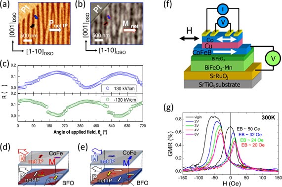
Figure 15. Control of the magnetic state by electric field. (a) In-plane PFM image of FE domains in BFO. (b) XMCD-PEEM image of the CoFe/BFO heterostructure. The grey (blue) and black arrows in (b) and (c) correspond to the in-plane projections of the polarizations in each of the ferroelectric domains of BFO and to the magnetic moments in the CoFe layer, respectively. (c) AMR response after application of a 130 and −130 kV cm−1 electric-field pulse, and (d), (e) representations of the magnetic interface coupling in the CoFe/BFO heterostructure. The local change of the magnetization by 90° when the FE polarization is rotated by 71° results in a reversible 180° reversal of the net magnetization. (f) Illustration of an Au 6 nm/Co 4 nm/Cu 4 nm/CoFeB 4 nm spin valve and (g) GMR curves of the spin valve after different poling pulses applied to the BFO/BFOMn bilayer. (a), (e) Reprinted with permission from [286]. Copyright 2011 American Physical Society. (f), (g) reprinted with permission from [290]. Copyright 2012 American Chemical Society.
Download figure:
Standard image High-resolution imageFrom a device point of view, it is crucial to work in the vertical geometry which allows operation at moderate voltages, being thus compatible with standard integrated electronics. Zhang et al [288] and Allibe et al [289, 290] investigated the prospect of electrically controlling the magnetic state of a spin valve exchange-biased with BFO. The latter paper evidenced a strong reduction of the exchange bias of a Co72Fe8B20/Cu/Co spin valve upon application of a moderate voltage, which manifests itself as a progressive shift of the giant magnetoresistance (GMR) signal (see figure 15(f)) [290].
In FeFET devices, the accumulation and depletion of charge from the BFO can modify the magnetic properties of an adjacent manganite channel [249, 250]. When cooled in the presence of a magnetic field, the BFO/LSMO system exhibits an exchange bias, and a magnetic moment is induced in the BFO [291]. As inferred from magnetoresistance curves collected for both polarization states both the magnetic coercive field and the exchange field are sensitive to the direction of polarization in BFO (that is, to the accumulation or depletion of carriers in the manganite channel). The former may reflect changes in the magnetocrystalline anistropy. For the latter, various mechanisms have been proposed, mainly relying on the influence of voltage on the magnetic moment in the LSMO [250, 292]. This electric-field control of exchange bias appears to be reversible but is limited to temperatures below about 30 K.
We have already mentioned that ultrathin BFO films can be used as tunnel barrier, and their ferroelectric character can produce giant tunnel electroresistance. When two ferromagnetic electrodes are used, tunnel magnetoresistance (TMR) can also be observed, as reported by Béa et al [283, 293] in LSMO/BFO/Co junctions. Interestingly the TMR is positive, in contrast with the situation in junctions combining LSMO and Co with other perovskite oxide barriers such as STO [294], TiO2 [295], LaAlO3 [296] or BaTiO3 [297, 298]. This deserves further investigation to clarify the role of the spin-polarized density of states at the BFO/Co interface and possible spin-filtering effects by the BFO barrier. A TMR of about 60% was also reported by Hambe et al in LSMO/BFO/LSMO junctions [263], this value being weakly dependent on the ferroelectric polarization direction.
6.3. For optics
The large birefringence of BFO has clear potential in optical applications. Since the ferroelectric polarization direction defines the optic axis, rotating the polarization (either by 71° or 109° switching) is a simple way to induce a large change (∼0.2) in the refractive index. A plasmonic resonator/switch making use of this effect was proposed [299]; in this work the authors modelled the performance of a modulator based on an Au-wire grating on top of a 500 nm thick BFO film. The results suggested a strong modulation—around 30 dB—of the reflected beam amplitude depending on the polarization of the BFO layer. However, no working device prototype was reported.
In addition to the birefringence, as discussed in section 5, BFO has a sizeable electro-optic effect. This naturally could lend itself to application in thin-film optical modulators [300]. There are many technological problems to be overcome, not least of all how to reliably manufacture thick single-domain films, and how to guide a laser beam in a length of modulator long enough to yield a significant modulation of the beam, without large losses. Integration on substrates with a low dielectric constant can offer modulation over a wide range of frequency and bandwidth [209]. The T-like phase of BFO probably shows more promise for devices. Since it has a larger ferroelectric distortion, one can probably expect that its birefringence will be even higher than that of the R-like phase.
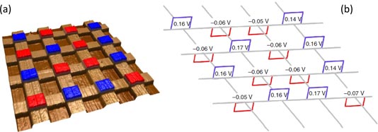
The bulk photovoltaic effect has been utilized in a prototype memory [301]. Here the BFO was the active storage medium in what was essentially a Fe-RAM, and upon illumination with a uniform light field, the BPV effect induced a voltage across the memory cell that was dependent on the ferroelectric polarization. Reading out the data was straightforward, as simply a voltage had to be read, avoiding the laborious re-writing step in Fe-RAM devices. Shown in figure 16, the proposed 16 cell device produced good retention properties, with no degradation after four months, and minimal ferroelectric switching fatigue.
Figure 16. Left: topography of a 16-bit memory for a ferroelectric photovoltaic memory prototype device, with blue indicating polarization up, red indicating polarization down. Right: measured photovoltage VOC for each cell upon illumination of the device with 20 mW cm−2 light. Reprinted with permission from [301]. Copyright 2013 Nature Publishing Group.
Download figure:
Standard image High-resolution image
The bulk phase of BFO has been shown to exhibit photostriction [302, 303], arising from the combined influence of the bulk photovoltaic effect and inverse piezoelectricity. The effect appears to have a dependence on applied magnetic field as well, evidencing a spin-lattice coupling term. While this result has yet to be observed in thin films, the fact that BFO possesses such a wide array of properties opens the way to multifunctional devices making use of optical, magnetic, electric and elastic degrees of freedom in BFO thin films [304].
7. Conclusion and outlook
Among perovskite oxides, bismuth ferrite stands out as an extraordinarily multifunctional material. The coexistence of two antagonist structural instabilities—polar distortions and octahedra rotations—together with the presence of a magnetic ion with a large spin moment at the perovskite B site, produce a room-temperature multiferroic character, with coexisting ferroelectricity, ferroelasticity, and antiferromagnetism. The structure of BFO is also remarkably flexible, making it possible to tune the structural parameters of the bulk-derived R-like phase through epitaxial strain engineering over a range of more than 4% ; in addition, at high compressive and tensile strain, new polymorphs can be stabilized, with a giant c/a ratio [37] (T-like BFO) and orthorhombic symmetry [45], respectively. The multiferroic properties of these polymorphs still remain to be fully described, but T-like BFO has already been shown to display virtually coinciding ferroelectric and magnetic phase transitions just above room temperature [205, 207], holding promise of a large magnetoelectric response. A large piezoelectric effect can arise at boundaries between these structural phases [156, 305], as well as in rare-earth doped thin films [166].
In the R-like phase, strain has an anomalous influence on the ferroelectric properties, compared to the situation in a classical ferroelectric such as BaTiO3 [125]. Here, the Curie temperature is strongly reduced by strain, and the polarization hardly changes, due to the competing influence of polar and antiferrodistortive degrees of freedom [74]. However, a magnetoelastic anisotropy builds up as strain increases, which modifies and eventually destroys the bulk-like cycloidal spin modulation in favour of a pseudo-collinear antiferromagnetic (weak-ferromagnetic) state [75]. The average direction of the antiferromagnetic vector can be continuously strain-tuned from lying in the plane to out of the plane, and the transition between different magnetic orders strongly modifies the spin wave modes [75].
In addition to this highly tuneable multiferroic character, BFO has unique optical properties, such as a giant birefringence [32, 223] and a band gap in the visible range [210], which has revived the interest for photovoltaic effects in ferroelectric materials [306]. Couplings between optical properties and ferroic orders have also been demonstrated through electro-optical effects [223], magnetochromism [236] or magnetic-field dependent photostriction [302].
Another, recently discovered, exciting feature of BFO is conductivity at domain walls [8]. Whether its origin is intrinsic or due to defects remains a matter of hot debate. Regardless, this finding gave birth to a new sub-field, focusing on one hand on the characterization of the structural, electronic, magnetic and optical response of BFO at the local scale of a domain wall, and on the other hand, on the exploration of domain wall properties in other ferroelectrics, both proper and improper.
This profusion of properties obviously offers a world of device opportunities. The very large polarization of BFO is appealing for memory applications: in ferroelectric random access memories (FeRAMs) [307], in ferroelectric FETs (in which large carrier modulation effects in adjacent correlated oxide channels have been demonstrated [246, 308]) or in ferroelectric tunnel junctions. In the latter devices a BFO tunnel barrier can give rise to giant tunnel electroresistance, with huge OFF/ON resistance ratios [264], good endurance, and near-GHz operation speed [270]. Furthermore, the domain structure in the barrier can be harnessed to produce a memristive behaviour [264], expanding the interest of ferroelectrics to computational architectures.
The original motivation underpinning the rediscovery of BFO was the control of magnetic properties by electric fields [123], and the realization of magnetoelectric memories in which information is stored magnetically, but written (and read) by electrical means only [6]. The route towards this goal has been long and full of obstacles. Much progress has however been made through careful control of the multiferroic domain structure [88], its coupling to ferromagnetic domains in an adjacent transition metal alloy [199, 284] and their manipulation with a voltage [287]. Endurance, scalability, and CMOS compatibility will have to be assessed to benchmark the true potential of BFO for low-power spintronics.
Despite all these advances, many pertinent questions remain. Is the ferroelectric polarization of pure T-like BFO really 150 µC cm−2, as initially conjectured [36, 90]? Can BFO be engineered to show a large magnetoelectric response at room temperature? Can more novel magnetic orders be stabilized? Is it possible to enhance the quantum efficiency in photovoltaic experiments? Can the piezoelectric response be enhanced to qualify BFO as viable replacement for lead-based ferroelectrics? What is the true potential of BFO-based domain wall nanoelectronics? These are of course just a few examples. More generally, the many coupling opportunities (see figure 2) between the various degrees of freedom present in BFO have hardly been explored, for instance to control the optical response by strain, spin waves by electric fields [309], magnetism by light, etc. A vast unchartered territory still lies ahead. It will undoubtedly take another decade of research to explore.
Acknowledgments
This work was supported by the French Research Agency (ANR) projets 'Méloïc', 'Nomilops' and 'Multidolls' and by the European Research Council Advanced Grant 'FEMMES' (contract no 267579). We wish to thank D R Mason, G Radaelli, S Fusil, L Bellaiche and J ĺñiguez for critical reading of this manuscript.
Footnotes
- 3
Here we note that while both belong to the Cc or Cm space group (with or without oxygen octahedra rotations respectively), the difference between MB and MA symmetries is that for MB, cmc < bmc ≈ amc, while for MA, cmc>bmc ≈ amc [160].