

Abstract
This paper reports the progress made at JET-ILW on integrating the requirements of the reference ITER baseline scenario with normalized confinement factor of 1, at a normalized pressure of 1.8 together with partially detached divertor whilst maintaining these conditions over many energy confinement times. The 2.5 MA high triangularity ELMy H-modes are studied with two different divertor configurations with D-gas injection and nitrogen seeding. The power load reduction with N seeding is reported. The relationship between an increase in energy confinement and pedestal pressure with triangularity is investigated. The operational space of both plasma configurations is studied together with the ELM energy losses and stability of the pedestal of unseeded and seeded plasmas. The achievement of stationary plasma conditions over many energy confinement times is also reported.
Export citation and abstract BibTeX RIS
1. Introduction
ITER operation with high fusion gain (QDT = 10) is based on inductive 15 MA plasmas in a type-I ELMy H-mode regime with a deuterium–tritium mixture. This ITER inductive scenario is based on a sufficiently normalized energy confinement (H98(y,2) ~ 1) at a normalized pressure βN ~ 1.8, high density compared to the Greenwald density limit nGW (nGW = Ip/2πa2 with Ip the plasma current and the minor radius a; fGW = <n > /nGW ~ 0.85) at high fuel purity (Zeff ~ 1.6) [1]. The inductive scenario is based on integrating the above plasma performance for the confined plasma (core plasma) whilst keeping within divertor conditions compatible with the plasma facing components (PFCs). ITER will have beryllium (Be) PFCs at the main wall and tungsten (W) PFCs at the divertor for minimum impurity contamination of confined plasma together with minimum fuel retention. The challenge is in the integration of these plasma core requirements together with divertor conditions compatible with the PFCs, acceptable ELMs and to achieve stationary plasma for a duration of tstat ~ 400 s (i.e. 100 times the energy confinement time τE ~ 3.5 s) [2].
It is imperative to have edge conditions compatible with the PFCs both in the inter-ELM phase and during ELMs. High divertor radiation from extrinsic impurity will be mandatory for compatibility of power load with the divertor targets in the inter-ELM phase. It is estimated that the inter-ELM peak power load at the divertor is 20–40 MW m−2 for attached conditions and needs to be reduced down to less than 10 MW m−2 for compatibility with the PFCs [3, 4]. Modelling indicates that to satisfy these demanding requirements regarding divertor power handling control, while providing appropriate He exhaust and maintaining an acceptably low core impurity concentration [5, 6], ITER has to operate with a partially detached divertor (only the region near the separatrix is detached-evidencing local pressure loss).Under these conditions 80% of the input power needs to be radiated. For the seed impurity, ITER plans to have the flexibility to use Ne, Ar and N (or a mixture thereof) as seed gases. Chemically reactive species will be more of a safety challenge for the plant than a noble gas). In addition, the ELM energy losses will be restricted to be less than 0.7 MJ, which corresponds roughly to ΔWelm/Wped below 1%, and will require active ELM control [7].
The pedestal is key to achieving the challenging integration of plasma core performance and divertor conditions compatible with the PFCs. The core plasma requirements necessitate a high pedestal plasma density and temperature. Indeed, the energy confinement and fusion gain are strongly affected by the pedestal temperature due to profile stiffness. Also a high core plasma density is best achieved keeping the plasma density only moderately peaked with a high pedestal density to avoid magneto-hydrodynamic (MHD) instabilities and impurity peaking. However, the pedestal temperature decreases with increasing pedestal density as the pedestal pressure is limited by ELMs to be a nearly constant value [1]. So for a value H98(y,2) of about 1 to be achieved at high density, improved pedestal pressure at high nped/nGW is important. ITER inductive scenario is designed at high plasma triangularity δ ~ 0.4. It relies on the improved pedestal stability of high triangularity plasma, for which the pedestal pressure is higher than in low δ discharges at a given pedestal density.
Achieving partially detached divertor conditions with extrinsic impurity whilst maintaining the requirement of H98(y,2) ~ 1, βN ~ 1.8 and high fuel purity is a challenge for the H-mode pedestal, in particular, due to the closeness of the operational point of the inductive scenario to the back-transition from H-mode to L-mode confinement. At present, the input power threshold for the inductive scenario is expected to be ~70 MW and the power through the separatrix ~79 MW [8]. It is expected that in ITER the reference inductive scenario operation will relatively close to the type-III operational boundary [9] as well as H to L threshold.
In this paper, we report progress made in integrating ITER-relevant core and edge plasmas within the constraints of an ITER-like wall at JET (JET-ILW). The aim of this paper is to assess the current status of the integration of plasma performance in JET for seeded ITER scenario, highlighting differences between JET-C (with C PFC) and JET-ILW, and reporting key shortcomings in our understanding as well as key achievement. The dynamic phase of the current ramp-up and ramp-down times and the requirements for active ELM control in impurity seeded plasmas will not be discussed in this paper. Also, in this paper the discussion is restricted to nitrogen (N) seeded plasmas. Nitrogen as an extrinsic radiator has a role to play in the development of radiative scenario in current devices for two important reasons: firstly, due to its lower ionization energy, it plays the role that neon will have under ITER divertor conditions where the pedestal will be hot ~4–5 keV compared to ~1 keV in JET-C, and secondly it isolates the effect that high divertor radiation power load reduction has on pedestal performance [10].
This paper is organized as follows: a description of the scenarios considered in this paper is given in section 2; the reduction of the power load to the divertor is described in section 3; the impact of the extrinsic radiation on energy confinement, pedestal pressure and dependence on plasma triangularity is discussed in section 4; the achievement of stationary plasma conditions is presented in section 5; section 6 will present the status of plasma integrated performance at JET-ILW and finally a conclusion will be given in section 7.
2. Description of experiments
This paper concentrates on fuelled and nitrogen-seeded ELMy H-mode plasma at 2.5 MA and at high plasma triangularity. The reference ELMy H-mode plasma in JET-C has a plasma field and current of 2.5 MA/2.6–2.7 T, q95 ~ 3.5, Pin ~ 16 MW, δ ~ 0.4 (the average plasma triangularity), H98(y,2) ~ 1.0 [10–13]. The divertor geometry of the chosen configuration has the inner strike on the vertical divertor target and the outer strike on the horizontal divertor target as shown in figure 1(a). In this paper, these plasmas will be referred as JET-C high-δ HT plasmas, i.e. high-δ horizontal target divertor plasmas. Deuterium and nitrogen were injected at the divertor target respectively from the high-field side (HFS) divertor target and from the low field side into the common-flux region, as discussed in more details in [13]. In JET-ILW, similar discharges were repeated at 2.5 MA/2.65 T, δ ~ 0.37, Pin ~ 15–17 MW, with a similar divertor geometry as shown in figure 1(a). These plasmas will be referred to in this paper as JET-ILW high-δ HT plasmas. The JET-C and JET-ILW high-δ HT plasmas correspond to the best set of ELMy H-mode discharges that document the change of wall in terms of pedestal characteristics and power load for a range of pedestal densities.

Figure 1. Five plasma configurations used in this study (a): the high-δ horizontal divertor target (HT) plasmas in JET-C in blue (#76666 at 20 s) and JET-ILW in red, (#82806 at 15 s); (b) the low-δ HT (#83177 at 15 s); (c) the high-δ vertical divertor target (VT) plasmas with both inner and outer strike on vertical divertor plates (85267 at 15 s); (d) the low-δ VT plasmas (#83487 at 15 s). The inset illustrates the difference in divertor configuration between the HT (blue) and VT plasmas (in red). Configurations in red were used in JET-ILW and in blue in JET-C. The black line delimits the definition for divertor/xpoint radiation and main plasma radiation in this paper.
Download figure:
Standard image High-resolution imageA low triangularity plasma configuration was developed for JET-ILW, here referred to as low-δ HT plasmas, with similar divertor geometry as the high-δ HT as seen in figures 1(a) and (b) similar plasma volume, see table 1. Plasmas with divertor configuration closer to the ITER divertor are also considered. Low and high-δ plasmas with both inner and outer strike on the vertical targets have been developed, referred to respectively as low-δ and high-δ VT plasmas, see figures 1(c) and (d). The positions of deuterium and nitrogen injection were unchanged with respect to JET-C high-δ HT plasmas. More information can be found in table 1 and in [13, 14]. Whether in JET-C or JET-ILW, it is measured that for the plasma presented in this paper the ion temperature is equal to the electron temperature over the whole profile.
Table 1. Summary of key parameters for plasma scenario of all JET pulses considered in this paper.
| high-δ HT JET-C | high-δ HT JET-ILW | high-δ VT JET-ILW | low-δ HT JET-ILW | low-δ VT JET-ILW | |
|---|---|---|---|---|---|
| Ip/Bt | 2.5 MA/2.7 T | 2.5 MA/2.7 T | 2.5 MA/2.7 T | 2.5 MA/2.7 T | 2.5 MA/2.8 T |
| q95 | 3.5 | 3.4 | 3.2 | 3.4 | 3.4 |
| Upper/lower δ | 0.44/0.39 | 0.37/0.37 | 0.40/0.34 | 0.35/0.19 | 0.26/0.18 |
| Plasma vol (m−3) | 74 | 74 | 72 | 75 | 76 |
| PNBI/PRF (MW) | 14–15/1.5 | 14–18/0–4 | 15–17/0–4 | 15–20/0 | 16/0 |
| D2 Γel (1022 el s−1) | 0.22–6.0 | 0.7–4.5 | 0.9–2.9 | 0.8–2.7 | 2.8 |
| N Γel (1022 el s−1) | 0–4.5 | 0–3.6 | 0–3.4 | 0–2.5 | 2.18 |
The effect of seeding on low-δ ELMy H-mode will not be discussed in details in this paper mostly due to a lack of space but has already been investigated in related publications [15–17]. The approach is taken in this paper to mostly document and compare the effect of seeding on high-δ ELMy H-mode plasmas to fuelled only plasmas. The main plasma, Prad,main, and divertor, Prad,div, radiated power were determined from tomographic reconstruction by integrating the 2D reconstruction from the z-abscissa value greater than −1.2 m for Prad,main and for Prad,div with z less than −1.2 m, see figure 1. In other words, the x-point radiated power is included in the divertor radiated power in this paper [13].
For the remainder of this paper, it is useful to note that in most tokamak devices with carbon-fibre composite (CFC) as plasma facing materials, in high triangularity δ plasmas, a higher edge pedestal pressure at high <ne > /nGW can be maintained than in low δ discharges [18–20], due to the improved MHD stability of the pedestal. In JET it was even observed that for the JET-C high-δ HT plasma, a high energy confinement H98(y,2) ~ 0.9–1 at <ne > /nGW could be achieved with D-gas injection and is linked to the mixed type-I/II ELMy regime characterized by higher pedestal pressure than pure type-I ELMs [10]. Other devices did see an improvement of pedestal pressure with triangularity at a given <ne > /nGW but in all cases the global energy confinement drops as the edge density is increased with increasing D-gas injection, unlike the ITER baseline scenario case at JET [10].
3. Achievement of partial and full detachment in JET-C and JET-ILW
Divertor detachment can lead to a significant reduction of the power arriving at the outer divertor target (OT) with respect to the power flowing through the separatrix (Psep). These conditions are obtained by lowering the plasma temperature at the OT in the inter-ELM phase either by decreasing the separatrix temperature or by radiation from seed impurity in the scrape-off-layer (SOL) and divertor. Below only the power load at the outer strike is discussed as the inner strike point is fully detached.
In JET-C, it was possible in the high-δ HT plasmas (introduced in section 2) to reach partial detachment with D-gas alone [12, 13] at rate of 2.8 × 10²² el s−1 (#76678). Although modelling with the EDGE2D-Eirene code of these JET-C discharges established that it was through an increased C (carbon) divertor radiation [21] induced by increased D sputtering and not D radiation alone. The radiative fraction frad (Prad/Pin with Prad the total radiated power and Pin the input power) only modestly increased from 0.44 (#76666) for the reference low fuelled discharge (with attached divertor conditions) to 0.55 (#76678) for partially or even detached divertor conditions, with a ratio Prad,div/Prad,main ~ 0.7 (with Prad,div and Prad,main being the radiated power in the divertor and in the main plasma, respectively). A higher radiative fraction was therefore not necessary to achieve the required divertor conditions. Both in attached and partially detached divertor conditions, the divertor radiation was located at the X-point as shown in [13].
In JET-ILW, the strong reduction of the C concentration by a factor of 10 [22] led to reduced divertor radiation and subsequent higher divertor power load. In JET-ILW, the high-δ HT plasma with a D-gas rate of 2.8 × 10²² el s−1 and input power similar to the JET-C reference pulse (#76678) is repeated. Whereas the divertor conditions were partially detached in JET-C [12], the divertor remained in attached conditions in JET-ILW (#82806) as shown for the unseeded case in figure 2(a). The power load increased from JET-C to JET-ILW from 0.22 to 0.3 × Psep and the plasma temperature at the divertor target increased from ~5 to 26 eV [14], due to the absence of C as intrinsic radiator. The radiative fraction decreased from frad ~ 0.55 and Prad,div/Prad,main ~ 0.7 in JET-C (#76678), down to ~0.3 with Prad,div/Prad,main ~ 0.3 [14] in JET-ILW (#82806).

Figure 2. JET-ILW Ion saturation current profiles (Isat in MA m−2) and electron temperature profiles (TeOT in eV) at outer divertor target measured by Langmuir probes (LP): (a) and (b) are the Isat and TeOT profiles for high-δ HT plasmas at different N-seeding rate (ΓN ~ 0 × 1022 el s−1 (#82806), ΓN ~ 2.4 × 10²² el s−1 (#82812) and ΓN ~ 3.6 × 10²² el s−1(#82811)), and at the D-gas rate of 2.8 × 10²² el s−1. (c) and (d) are the Isat and TeOT profiles for high-δ VT plasmas at the D-gas rate of 2 × 10²² el s−1 and at increasing N-seeding rate (ΓN ~ 0 (#85262), ΓN ~ 1.2 (#85272) and ΓN ~ 1.8 (#85266) and ΓN ~ 3 × 10²² el s−1(#85270)).
Download figure:
Standard image High-resolution imageIt was shown for JET-ILW in [14] that, independently of the D-gas rate, and with a high enough N-seeding rate, similar conditions of frad ~ 0.55 and value of the ratio Prad,div/Prad,main ~ 0.7 can be obtained resulting in very similar reduction in the power load at the OT target compared to the JET-C reference pulse (#76678) and with the radiation again located at the X-point. Figures 2(a) and (b) show that in high-δ HT plasmas at increasing N-seeding rate, the ion current decreases and temperature drop at the strike point divertor, both signs of partially detached divertor conditions. In high-δ VT plasmas, divertor conditions of partial detachment were also reached as shown in figures 2(c) and (d). In fact, it was shown for both divertor configurations that if the radiative power in the divertor was about 40% of Psep in high-δ HT plasmas, the power reaching the OT will be substantially reduced and the divertor conditions will be partially detached, see figure 3. It was found that this figure of merit (Prad,div ~ 40% of Psep) is also a sufficient condition for achieving these conditions in the JET-C high-δ HT plasmas (not shown here) as well as for the JET-ILW high-δ VT plasmas, see figure 3.
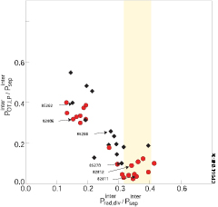
Figure 3. Ratio of power reaching the OT measured with LP to power flowing through the separatrix (Psep) versus ratio of divertor radiation to Psep in the inter-ELM period for JET-for two divertor configurations: high-δ HT (red circles) and VT plasmas (black diamonds).
Download figure:
Standard image High-resolution imageEDGE2D-EIRENE modelling of high-δ HT plasmas in JET-ILW has been carried out. Reference [23] demonstrates that EDGE2D-EIRENE was able to capture the detachment processes induced by N as measured in experiment for both power and ion current at the outer target. Similar to the experimental observations, in the simulations a factor 10 reduction in divertor power load was obtained when the divertor radiation is about 50% of Psep. Finally, the peak outer divertor power and particle flux reduction in the nitrogen induced detached conditions is obtained almost solely via nitrogen radiation, and associated reduction in the power flow to the deuterium ionization and recycling front. As a result, the divertor particle fluxes in detachment are reduced without the need for strong recombination sink for particles in front of the targets, highlighting that the processes in impurity injection induced detachment can be different than in D-gas induced detachment.
Moreover, it is compulsory in ITER scenarios to have edge conditions compatible with the PFCs not only during the inter-ELM period but also during the ELMs. With N injected for inter-ELM power-load reduction, the ELM energy losses and frequency can have a complex behaviour as a result. It is important to stress that no difference for the energy deposition fluency εELM during an ELM (kJ m−2) was observed between JET-C and JET-ILW and the peak deposited energy fluency remains dependent on the pedestal pressure [24]. The ELM energy losses will be discussed in section 4.3 as part of the description of the operational space of seeded high-δ HT and VT plasmas.
4. Dependence of the high-δ ELMy H-mode energy confinement on impurity
As mentioned in the introduction, the pedestal is key to achieving the challenging integration of plasma core performance and partially detached divertor conditions compatible with the PFCs. It is necessary to obtain in ITER a hot pedestal (Tped ~ 3–4 keV) at high density ne,ped/nGW ~ 0.6–0.7. It relies on the improved pedestal stability with higher plasma shaping, for which the pedestal pressure is higher than in low-δ plasma at a given pedestal density. From section 3, it might be inferred that the change of wall material had not particularly impacted the energy confinement of high-δ horizontal target plasmas. This is far from being the case. The change of wall from JET-C to JET-ILW has brought major changes in the pedestal confinement of high-δ plasmas and this has been an active area of research since the first ILW campaign.
Section 4 is organized as follows: a brief summary of the major findings obtained by comparing high-δ plasmas in JET-C and JET-ILW is given in section 4.1 and will be referred in the rest of the section; the improvement of pedestal pressure with nitrogen-seeding is shown to be dependent on plasma triangularity and not specific to the high-δ HT plasmas in section 4.2; a comparison of the operational space of N-seeded high-δ plasmas in JET-C and JET-ILW is done with identification of the best integrated plasma scenarios in section 4.3; Finally a closer investigation of the effect of N-seeding on the pedestal of high-δ plasma is made by looking at the pedestal structure in section 4.4.1, and PB-stability and ELMs in section 4.4.2. The results on the effect of N-seeding on pedestal confinement are summarized and discussed in section 4.4.3.
4.1. Energy confinement and pedestal in fuelled and seeded high-δ HT plasmas in JET-ILW and JET-C
In the last JET-C campaign prior to the change of wall, experiments were carried out in high-δ HT ELMy H-mode, as presented in section 2, in which the D-gas injection was varied and pedestal, core profiles were well diagnosed. Similar discharges were repeated in JET-ILW to those reference high-δ HT plasmas in JET-C. It was expected that tungsten (W) contamination in the main plasma would limit operation at low density due to both high W source resulting in excessive main plasma radiation, and to excessive divertor power load due the lack of C as an intrinsic radiator. It came as a surprise however that at higher pedestal density the same performance of H98(y,2) ~ 0.95, βN ~ 1.9 (as for #76678) could not be achieved when the scenario was repeated in JET-ILW [14, 25]. In figure 4 with the same net power of Pnet ~ 10 MW (Pnet = Pin − Prad,main), a reduction in stored energy was observed of up to 40% and H98(y,2) ~ 0.7, βN ~ 1.1 (#82806) while still featuring type-I like ELMs with large ELM-energy losses, see section 4.4.2 [14]. The reduction in stored energy stems from a reduction in the pedestal pressure [14, 15, 17] and mostly the pedestal temperature as shown in figure 5.

Figure 4. Stored energy versus Pnet in unseeded high − δ HT plasma in JET-C and JET-ILW, in blue and red respectively. Filled red symbol correspond to N-seeded discharges. Pnet is the input power Pin minus the radiative power in the main plasmas, Prad,main.
Download figure:
Standard image High-resolution image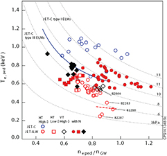
Figure 5. Pre-ELM pedestal temperature versus pedestal density for JET-C (Blue symbols) and JET-ILW: red circles for high-δ HT plasmas; black diamonds for high-δ VT plasmas; and red squares for low-δ HT plasmas. Filled symbols correspond to N-seeded discharges. The blue line indicated the experimentally observed threshold for the transition from type-I to type-III ELM regime in JET-C [14]. The red dashed line indicates where the area of transition from type-I to type-III ELM regime is suspected to be in JET-ILW.
Download figure:
Standard image High-resolution imageAn additional unexpected observation is the fact that the JET-ILW plasmas with type-I like ELMs, such as #82806, exists below the critical electron pedestal temperature for type-III ELMs in JET with a carbon wall [14] at high densities as shown in figure 5. In order to identify the position of the back-transition from type-I to type-III ELM regime for the 2.5 MA plasma in JET-ILW, once the H-mode has been established for a few seconds, the power is reduced to different constant input power in successive discharges, see figure 6. The transition from type-I to type-III ELMs appears at reduced pedestal temperature at a Te,ped ~ 0.35 keV for ne,ped/ngw ~ 0.85 (#82283, #82290). The boundary between type-I and type-III ELM regimes, which was such a key player in both ELM dynamics and drop in confinement in JET-C discharges as a result of seeding [13], seems to lie far below its previous position at Te,ped ~ 0.7 keV, shown in figure 5. In addition the triangularity seems to have no beneficial effect on the pedestal pressure as discharges with a similar pedestal density and different triangularity have a similar pedestal pressure as shown in reference [15] and illustrated in figure 5 with unseeded high and low-δ HT plasmas at βN below 1.5. Major changes seem to have taken place in the behaviour of the high-δ plasma pedestal with a change of the plasma facing materials.
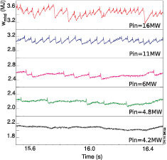
Figure 6. Stored energy versus time of unseeded high-δ HT plasmas at gas rate ~3–4 × 10²² el s−1. where once the ELMy H-mode has been established for 2 s, the input power was lowered to a constant input power (phase shown here), for shot #83357 (Pin = 16 MW), #82283 (Pin = 11 MW), #82290 (Pin = 6 MW), #82286 (Pin = 4.8 MW), #82287 (Pin = 4.2 MW). The corresponding pedestal electron temperature and density are shown in figure 5.
Download figure:
Standard image High-resolution imageAlthough nitrogen was first injected to increase divertor radiation and reduce power loads, nitrogen seeding has been found to improve plasma energy confinement in the high-δ HT plasma [14]. When nitrogen is injected into deuterium-fuelled high-δ HT plasmas in JET-ILW, it raises the pedestal density and temperature leading to an increase in stored energy to 5.5 MJ close to the JET-C fuelled counterpart [14], which had a stored energy of 6 MJ, see figure 4. It was unexpected that N-seeding lead to an increase of the H-mode pedestal pressure, mainly temperature, partially recovering the pedestal pressure of unseeded JET-C high-δ HT plasmas as shown in figure 5. N was also seeded in the low-δ HT plasma but the improvement in pedestal pressure was not as prominent as shown in figure 5. The improvement of confinement at high-δ HT with respect to low-δ HT plasmas at a given pedestal density seems to have been re-established with nitrogen seeding [15].
The following hypotheses were raised on possible explanation for loss of pedestal pressure for high-δ ELMy H-mode in JET-ILW. The first idea was that the energy confinement was reduced due to a decrease of Psep linked to the increased core radiation with the presence of W in the confined plasma. The total radiation as well as the radiative power from the main and divertor plasmas is much reduced in comparison to JET-C counterpart, see figures 2 and 12 in [14], and this idea could be dismissed. Secondly, a decrease of Psep via an increase energy loss channel in ILW via neutrals (charge-exchange losses or momentum losses) was also put forward [26]. Modelling has been carried out in EDGE2D-EIRENE and show that in fact the D0 flux across the separatrix increases with increasing divertor radiation for the high-δ HT configuration. As a result, in the unseeded JET plasmas, the neutral D-gas through the separatrix in JET-C is predicted to be 20% higher than in the JET-ILW plasmas. A reduction of energy or momentum confinement due to enhanced losses via neutrals is unlikely to be the reason. The details of this work will be reported in [27, 28]. Thirdly, it has been demonstrated that the pedestal ion-dilution by means of nitrogen seeding cannot account for the confinement improvement with nitrogen seeding. This mechanism requires strong edge peaking of the impurity concentration, which has not been observed in JET [15].
Finally, the last hypothesis to explain the loss of pedestal pressure in the high-δ ELMy H-mode is that the pedestal stability and structure has been affected by a change of possibly fuel recycling and/or decrease of C content. It was shown that D injection and N seeding can affect the pedestal pressure due to changes in the pedestal width and gradient [15, 16]. In high-δ HT plasmas in JET-C, the pedestal width increases with increased D-gas rate while the pedestal pressure gradient is only modestly reduced. It results in an increased pedestal pressure [29]. In JET-ILW the pedestal is also seen to widen in a D-gas scan, but the pedestal pressure height does not increase in this case, as the pressure gradient is strongly reduced at the same time as the pedestal widens. In contrast, in nitrogen seeded high-δ HT plasmas, the pedestal pressure width increases concurrently to a small decrease in the pedestal pressure gradient which results in an increase in the pedestal pressure [16]. The details of the mechanism at play in the loss of pedestal pressure from JET-C to JET-ILW are not well understood at present, nor its partial recovery with nitrogen seeding. The approach is taken in this paper to gather further experimental evidence on the effect of nitrogen seeding on the confinement and pedestal stability.
4.2. Effect of N-seeding and plasma triangularity on energy confinement in plasma with vertical divertor targets
As mentioned in section 2, the high-δ HT plasma configuration in JET-C had the peculiar behaviour to keep at high <ne > /nGW a similar confinement (H98(y,2) ~ 1) than at low <ne > /nGW, unlike observations make on other devices [10]. Therefore, we want to verify first that the increase in pedestal pressure with N is linked to the high triangularity and not specific to the high-δ HT configuration. In this section, we compare the confinement response to N-seeding in VT plasmas with both low and high triangularity plasma shaping.
An experiment was conducted in VT plasmas where the plasma triangularity was changed from low δ ~ 0.22 to high δ ~ 0.36 whilst keeping the vertical target divertor configuration unchanged as well as using the same heating, D-gas and seeding waveforms. Figure 7 illustrates that without N seeding an increase of the plasma triangularity raises the density, but does not improve the stored energy in VT plasmas, illustrating a similar result to the one observed in HT plasmas [15]. However, N seeding in low-δ VT plasma increases the stored energy by 15% whereas in high-δ VT plasma, N seeding increases the stored energy by 40%, see figure 8. No reference exists for this configuration in JET-C for comparison of the stored energy. These results clearly established that in JET-ILW, the increase in confinement with N-seeding is dependent on the plasma triangularity and not on the plasma configuration.
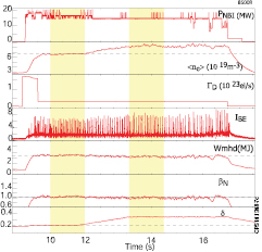
Figure 7. Dependence of stored energy with triangularity in unseeded plasma: highlighted region show the time window for low-δ VT (δ = 0.22) and high-δ VT plasmas (δ = 0.36).
Download figure:
Standard image High-resolution image
Figure 8. Dependence of stored energy with plasma triangularity and N-seeding for VT plasma: (from top to bottom) neutral beam heating, N-seeding rate, triangularity, stored energy, normalized pressure, H98(y,2) for pulse #85415 with δ = 0.36 and no nitrogen (blue), #85417 with δ = 0.22 (pink) and with nitrogen for pulse #85419 with δ = 0.36 (red). The delayed rise in the stored energy following the nitrogen seeding for pulse #85417 and #85419 is related to rise of N content in the discharge (not shown here).
Download figure:
Standard image High-resolution imageAn investigation of the improvement in the energy confinement and pedestal pressure with N-seeding in high-δ VT and HT plasma is done in section 4.4, highlighting similarities and differences. Before that and keeping in sight that the overall aim of this paper is to review not only what has been learnt but also achieved on the integration of ITER-relevant core and edge plasmas, a comparison of the operational space of N-seeded high-δ plasmas in JET-C and JET-ILW is done with identification of the best integrated plasma performance in the following section.
4.3. Operational space of high-δ plasmas with N seeding in JET-C and JET-ILW
The operational space of fuelled JET-C high-δ HT plasmas was already reported in previous papers [10–12, 17]. The operational diagram of H98 versus ne,ped/nGW for the JET-C high-δ HT plasmas is shown in figure 9 for a D-gas rate from 0 to 6 × 10²² el s−1 rate at constant input power (Pin ~ 16 MW) operating at Psep/PLH,ITER ~ 1.2. At low D-gas rate (ΓD ~ 0.4 × 10²² el s−1), H98(y,2) ~ 1 (#76666) can be achieved. When the D-gas rate is increased to ~3 × 10²² el s−1, the pedestal density increases to the Greenwald density limit, and a normalized confinement H98(y,2) ~ 0.95 can still be achieved. At this high density the plasma has made a transition from pure type I to mixed type I/II ELMs [10] (#76678 in figure 7). Details of the plasma performance, ELM energy losses and frequency are shown in table 2. As the gas rate is further increased towards 6 × 10²² el s−1, the density decreases and the plasma will eventually make a transition to the type-III ELM regime [30] with H98(y,2) ~ 0.8, as shown in figure 9. As discussed in [12, 13] and [17], in JET-C seeding nitrogen does not have a beneficial effect on the confinement and leads to a reduction of the pedestal density and normalized confinement as shown in figure 9. Starting from the unseeded discharges #76678, the ELM frequency increases as the N-seeding rate is increased from 0–1.5 × 10²² el s−1 (#76680) in successive discharges. Finally at the highest N-seeding rate of 3 × 10²² el s−1, the pedestal temperature Te,ped is reduced and the plasma make a transition to the type III ELM regime with a reduced pressure gradient and a degradation of the confinement with H98(y,2) ~ 0.78, ne,ped/nGW ~ 0.7 (#76681). For lower gas rate, the same picture applies as nitrogen seeding rate is increased as shown in figure 9. In JET-C, the transition from type-I to type-III ELM regime turned out to be the limitation in achieving high divertor/X-point radiated power and H-factor close to 1 [13].
Table 2. Summary of performance and ELM energy losses of high-δ plasmas in this study: here are shown the configuration type, the D-gas and N-seeding rate, normalized confinement, ratio of ne,ped over nGW, normalized pressure, Zeff measured by bremsstrahlung, ELM energy losses, ELM frequency, and ratio of ELM energy losses over the stored pedestal energy. All pulses below #80000 shown in this table are from JET-C, the others are from JET-ILW.
| Pulse | config | ΓD (1022 el s−1) | ΓN (1022 el s−1) | H98 | ne,ped/nGW | βn | Zeff | ΔWelm (kJ) | felm (Hz) | ΔWelm/Wped (%) |
|---|---|---|---|---|---|---|---|---|---|---|
| 76666 | HT | 0.37 | 0 | 0.97 | 0.66 | 1.85 | 1.93 | 160 | 20 | 9 |
| 76678 | HT | 2.71 | 0 | 0.95 | 0.9 | 1.9 | 1.7 | 200 | 8 | 10 |
| 76687 | HT | 1.83 | 4.45 | 0.86 | 0.68 | 1.54 | 2.26 | 20 | 70 | 1 |
| 76681 | HT | 2.69 | 4.40 | 0.78 | 0.67 | 1.34 | 2.17 | 30 | 52 | 2 |
| 82806 | HT | 2.89 | 0 | 0.7 | 0.76 | 1.1 | 1.25 | 90 | 16 | 8 |
| 82810 | HT | 2.67 | 2.61 | 0.84 | 0.94 | 1.65 | 1.31 | 130 | 16 | 7 |
| 82812 | HT | 2.69 | 2.44 | 0.85 | 0.90 | 1.78 | 1.53 | 154 | 20 | 10 |
| 82819 |
HT | 0.84 | 2.53 | 0.87 | 0.70 | 1.60 | 1.65 | 64 | 35 | 5 |
| 82817 | HT | 1.49 | 2.93 | 0.90 | 0.85 | 1.82 | 1.43 | 153 | 20 | 9 |
| 85413 | HT | 2.74 | 3.46 | 0.81 | 0.80 | 1.70 | 1.54 | 100 | 32 | 6 |
| 85414 | HT | 2.76 | 3.56 | 0.85 | 0.81 | 1.93 | 1.56 | 80 | 40 | 4 |
| 82811 | HT | 2.84 | 3.61 | 0.80 | 0.81 | 1.50 | 1.72 | 70 | 40 | 5 |
| 85412 | HT | 2.61 | 3.46 | 0.86 | 0.76 | 1.6 | 1.9 | 66 | 48 | 5 |
| 85262 | VT | 2.71 | 0 | 0.61 | 0.70 | 1.06 | 1.28 | 95 | 13 | 10 |
| 85263 | VT | 2.11 | 0 | 0.60 | 0.72 | 1.03 | 1.26 | 100 | 14 | 10 |
| 85266 | VT | 2.10 | 1.79 | 0.83 | 0.63 | 1.53 | 1.63 | 54 | 50 | 4 |
| 85270 | VT | 2.13 | 3.0 | 0.85 | 0.63 | 1.61 | 1.60 | 57 | 53 | 3 |
| 85419 | VT | 2.9 | 2.6 | 0.85 | 0.64 | 1.6 | 1.5 | 65 | 45 | 5 |
aPulse corresponding to a data point that could not be reproduced on another experimental day.

Figure 9. H98(y,2) versus ratio of ELM-averaged electron pedestal density over Greenwald density for high-δ plasmas (fG = ne,ped/nGW). The lines and arrows indicate respectively in grey increase of D-gas rate in successive discharges in JET-C, in blue N-seeding rate in JET-C, in red N-seeding in (HT) and black (VT) in JET-ILW. The different Greenwald density fraction fGW between high-δ HT and VT is due to a different plasma cross-section not a different plasma edge density.
Download figure:
Standard image High-resolution imageIn JET-ILW, the unseeded high-δ HT plasmas have a reduced energy confinement in comparison to JET-C as already mentioned in section 4.1 (#82806). As nitrogen is injected with a constant D injection rate of ~2.8 × 10²² el s−1, the energy confinement is partially recovered and the ELM energy losses are increased from ~90 to ~130 kJ (#82810, see table 2). If the nitrogen seeding rate is further increased, a similar trajectory in ne,ped/nGW versus H98(y,2) diagram to the one observed in N seeded JET-C plasmas is obtained (as shown in figure 9 (also in [14]) and the pedestal density decreases, the ELM energy losses decreases from 130 to 70 kJ, the ELM frequency increases from 16 to 40 Hz and the energy confinement is reduced (e.g. #82811, see table 2). A detailed study of the effect of nitrogen-seeding on the ELM energy losses in high-δ HT plasma can be found in [31]. The unseeded high-δ VT plasmas are also shown in figure 9. The target D-gas rate in the high-δ VT plasmas (#85263, #85262) has been adjusted to obtain the same ELM averaged pedestal density (~7 × 10¹⁹ m−3) as the high-δ HT plasma reference pulse #82806. Similar ELM energy losses and frequency are obtained with a similarly low normalized confinement, see table 2. Figure 9 shows that as the N-seeding rate is increased in the high-δ VT plasma, the normalized confinement is increased. However, the ELMs energy losses reduced from ~95 to 54 kJ and become more frequent from 14 Hz up to ~56 Hz (e.g. #85262-unseeded and #85266-seeded in table 2). Opposite trends are observed for the pedestal density, which increases for high-δ HT plasmas whereas it decreases for the high-δ VT plasmas. In fact, high-δ plasmas with vertical target divertor geometry provide better control of the pedestal density than with a horizontal target configuration whilst maintaining the core plasma performance of high-δ HT N-seeded plasmas. It is likely that the difference in behavior in electron pedestal density is linked to the difference in divertor geometry and its effect on neutral recycling. This will be investigated in related publications.
It is now possible to identify from this operational domain with the information obtained on power load in section 3, the best candidates for an integrated plasma performance scenario, i.e. as high as possible normalized confinement, high density fGW ~ 0.85, a partially detached divertor and tolerable ELM energy losses (as a pragmatic criteria ΔWelm/Wped < 5% is chosen in this paper, as this is the detection limit of the stored energy measurements). The best candidates from the high-δ HT plasmas are pulse #76687 in JET-C, #85412 in high-δ HT and in #85419 in high-δ VT plasmas in JET-ILW (#85419 is not shown in figure 9 as the D-gas injection was higher than in #85262). It can be seen from table 2, that the obtained plasma performance are in fact fairly similar with H98(y,2) ~ 0.86, ne,ped/nGW ~0.6–0.76, βN ~ 1.5–1.6. Future experiments will have to address whether at higher input power the normalized confinement and pressure could be raised whilst maintaining small ELMs and partially detached divertor conditions.
4.4. Pedestal structure, peeling–ballooning stability of high triangularity plasmas, ELMs energy losses and ELM identification
The unexpected decrease in pedestal pressure from JET-C to JET-ILW has highlighted shortcoming in our understanding of the pedestal stability for high triangularity plasmas. It is still not known what mechanisms lead to low pedestal pressure in unseeded high-δ plasmas in JET-ILW with respect to JET-C, and what mechanisms lead with N to an increase pedestal pressure in high-δ plasmas in JET-ILW. The idea being investigated for high-δ plasmas is that the pedestal structure and stability are affected by a decrease in C content and/or change in fuel recycling. In this section, the improvement of the energy confinement and pedestal pressure with N-seeding in high-δ VT and HT plasmas is investigated, by looking at the pedestal structure, the pedestal stability, the ELM energy losses and ELM identification. The pedestal pressure is increased in both high-δ HT and VT plasmas but the reasons for this increase may not be exactly the same which possibly highlights that more than one mechanism could be at play. To keep this publication to a reasonable length, the N-seeded low-δ plasmas are not discussed in this section and will be the focus of a future publication.
4.4.1. Pedestal structure and stability of high triangularity N seeded plasmas.
More information can be obtained with the identification of common features between the high-δ VT and HT plasmas. For both configurations the ELM-averaged pedestal pressure and temperature increase as a result of the seeding, as shown in figure 10. However, opposite trends are observed for the average pedestal density, which increases in the high-δ HT plasmas whereas it decreases in the VT plasmas. At the seeding rate of ΓN ~ 2.5–3 × 10²² el s−1 and with gas rate corresponding to an ELM-averaged pedestal density of ne,ped ~ 7 × 10¹⁹ m−3 in the reference unseeded plasma, the relative increase in pedestal pressure is a factor ~1.6 in both configurations from their respective unseeded references. For the high-δ HT plasmas, the increase in pressure is due to a similar increase in density and temperature, i.e. a factor 1.2 and a factor 1.35 respectively. Whereas for the high-δ VT plasmas, the net increased pressure is due to an increased temperature (factor 1.9) as the density decreases (by a factor 0.85). So the benefit of N seeding on the global energy confinement is similar for the high-δ HT and VT plasmas. However, the Te–ne diagram in figure 5 shows that the pre-ELM pressure is significantly lower for high-δ VT than for the high-δ HT seeded plasmas. This is illustrated in figure 11 where the pre-ELM pedestal electron pressure, temperature and density are shown. For the high-δ VT plasmas, the pedestal pressure still shows a small increase with N injection but not as large an increase as seen from the ELM-averaged pedestal values, and not enough to explain the increase in global confinement. This difference is due to a reduction of the ELM energy losses with N seeding for high-δ VT plasmas, presented in section 4.4.2. Nevertheless, the common feature between the seeded high-δ HT and VT is the increase in pedestal pressure due to an increase in pedestal temperature with respect to the unseeded reference discharges. This trend is most clear in the pre-ELM pedestal data. Any future mechanism proposed for the increase in pedestal pressure with N injection will have to reproduce the trend in figures 10 and 11.
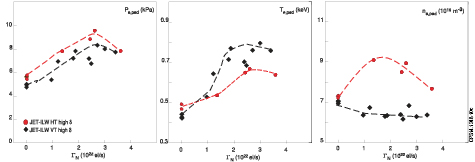
Figure 10. ELM-average pedestal electron pressure, temperature and density versus nitrogen seeding rate in high-δ HT and VT plasmas. Red circles correspond to high-δ HT plasmas. Black diamonds correspond to high-δ VT plasmas.
Download figure:
Standard image High-resolution image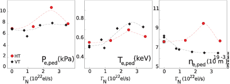
Figure 11. Pre-ELM pedestal pressure, temperature and density height in the time period 70–90% before an ELM as a function of the nitrogen seeding rate: black diamond correspond to high-δ VT plasmas. Circles correspond to high-δ HT plasmas, red and yellow for fuelling rate greater and lower than 2 × 10²² el s−1, respectively.
Download figure:
Standard image High-resolution image4.4.2. Peeling–ballooning stability of high-δ plasmas, ELMs energy losses and ELM identification.
A study of the peeling–ballooning (PB) stability of the unseeded and seeded high-δ HT and VT can help understanding the differences in the pre-ELM and ELM averaged observations. A concise summary on how the PB stability is calculated is first given, more details can be found in [29, 32] and references therein.
In the PB model the pedestal MHD stability is limited by current driven low n-number (n = 1–5) peeling modes and pressure gradient limited high n-number (n > 20) ballooning modes. The intermediate n-numbers (n = 5–20) are limited by combined PB modes. The PB model has been successfully tested in many tokamaks where high spatial resolution profiles are available of the pedestal electron and ion temperature, density and the impurity content [DIII-D, JET, AUG, JT-60U]. The determination of the PB stability analysis requires an ideal MHD eigenvalue solver such as MISHKA-I [33] and ELITE [34, 35]. The input data for this analysis is the total pressure profile P and edge bootstrap current profiles (Jped) (within plasma region 0.85 ≥ ψn ≥ 1.1) and plasma equilibrium. The total pressure profile is determined from the experimentally measured pre-ELM ion and electron temperature and density with P = neTe+ni(ne,Zeff). The edge current profile, not routinely measured in most tokamaks, is derived from the kinetic profiles using the Sauter formulae [36]. In this paper, and common for PB analysis at JET, the plasma equilibrium is self-consistently calculated with the HELENA equilibrium solver.
The PB stability is affected both by global pressure and plasma shaping. Increased global pressure renders the ballooning modes stable at higher pressure gradients. Increased plasma triangularity is expected to increase pressure gradients at high edge currents. At increased triangularity the PB stability can be extended to higher pedestal pressure only if sufficient edge current (Jped) can be sustained. At low edge current this beneficial effect of plasma triangularity is reduced. For convenience, the region of enhanced pedestal pressure gradient for increased edge current in the PB diagram will be colloquially referred to as the 'corner' in the PB diagram. This is the region that we want to access to achieve high pedestal pressure at high value of ne,ped/nGW. Due to the coupling of edge current and pedestal pressure gradient through the bootstrap current [36], access to the corner of the PB diagram depends on plasma collisionality. Unlike for type-I ELMy H-mode plasma, the pedestal of type-III ELMy H-mode is found not to be limited by PB stability.
A first attempt to verify if the pedestal pressure of high-δ HT plasmas in JET-ILW fuelled or seeded are indeed limited by the PB instabilities was reported in [15, 37]. Across a D-gas scan the pedestal moved from ballooning unstable to being fully stable with respect to PB modes, whereas the pedestal top pressure remained unchanged. All these plasmas featured type-I like ELM behaviour with large ELM energy losses, as is shown in figure 12 and in table 2. Figure 12 shows the time traces of the stored energy for a few examples indicating that experimentally these plasmas appear in type-I like ELMy H-mode with large ELM energy losses across the D-gas scan. In [15, 37] this observation questioned the validity of the PB model in its description of type-I ELMy H-mode pedestal stability.

Figure 12. Stored energy versus time of JET-ILW high-δ HT unseeded discharges, with for #82585, #82541, #82540, #82751, #82806 a D-gas rate of 0.9, 1.5,1.8, 3., 2.9, 4.4 × 10²² el s−1, respectively.
Download figure:
Standard image High-resolution imageHere we report on improved analysis of the PB stability of these plasmas. In previous studies of the pedestal stability it was found to be sufficient to analyse only up to n = 30 in the ELITE MHD stability code. However, the unseeded high-δ HT plasmas presented here feature cold pedestals with high collisionality, and therefore low edge current. For the plasmas at highest gas rates it was found necessary to go up to higher n-number in the PB analysis. Figure 13 shows the PB analysis with n ≤ 50 and even one example with n ≤ 70 using otherwise the same input parameters and kinetic profiles as in figure 13 of [15], which only went up to n = 30. It is clear from the comparison of the two figures that in the new analysis the slope of the ballooning boundary steepens and that the boundary moves towards the experimental data. There is still a degree of uncertainty in this analysis, as the ballooning stability at high collisionality may require PB stability calculations to even higher n-numbers. Further work would be needed for calculation of the bootstrap current at high D-gas rate [38]. Nevertheless, this analysis makes it plausible that the JET-ILW unseeded high-δ HT plasmas are indeed PB limited, and increasing the D-gas rate moves the experimental Jped–αmax point (Jped being the edge current and αmax the dimensionless normalized pressure gradient) to lower pressure gradient limited by the steep slope in the ballooning boundary. The total pedestal pressure remains unchanged as the pedestal widens when the gas rate in increases, as discussed in section 4.1.
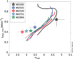
Figure 13. PB stability analysis for D-rate scan in JET-ILW high-δ HT plasma. The dashed line represents n < 70. The solid lines are calculated using n < 50.
Download figure:
Standard image High-resolution imageSimilarly to the high-δ HT plasmas, the unseeded high-δ VT plasmas also feature large type-I like ELMs as shown in figure 14. Here the D-gas rate scan is narrow but the operational points of these high-δ VT pedestals in the Jped–α diagram show that their pedestal are also marginally stable with respect to the ballooning boundary, see figure 15. In both configurations, the unseeded plasma is PB limited and in type-I ELM regime but the total stored energy is low.
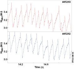
Figure 14. Stored energy versus time of unseeded high-δ VT plasmas. Stored energy versus time of JET-ILW high-δ VT unseeded discharges, with a D-rate rate of 2 × 10²² el s−1 respectively. The sharp peaks in the stored energy just prior to an ELM should be ignored and are due to the control system.
Download figure:
Standard image High-resolution image
Figure 15. PB stability analysis for fuelling scan in JET-ILW high-δ VT plasma. The solid lines are calculated using n < 50.
Download figure:
Standard image High-resolution imageThe same PB stability analysis was carried out for the seeded high-δ HT plasma. Figure 16 shows the stored energy of such plasmas, all at higher stored energy than the unseeded cases. The plasma with the highest stored energy (#82817) has considerable ELM energy losses (150 kJ) at low ELM frequency (20 Hz), a signature of the type-I ELM. The pedestal of the #82817 plasma is PB limited and the operational point approaches the corner of the PB diagram, for the plasma to fully benefit from plasma shaping with high triangularity Unlike the low D-gas HT plasma in figure 13 this plasmas features a wide pedestal [16] and the total pedestal pressure is increased. An additional interesting comparison is given by the pulses #85412 and #85413. The pulse #85412 has a slightly lower pedestal pressure and lower total stored energy at the same seeding and D-gas rate but different input power. The time traces in figure 16 reveal that this pulse also has a very different ELM behaviour with a much higher ELM frequency (48 Hz) and very small ELM energy losses (65 kJ), reaching the WMHD detection limit. Nevertheless, its total stored energy is significantly higher than the unseeded pulses in figure 12. The picture emerges that this pulse may no longer be in the type-I ELM regime but features type-III ELMs. The dependence of ELM frequency with input power, in figure 18, exhibits a bifurcation characteristic of a transition to type-III ELM regime [30]. This observation is further strengthened by pulse #82819 that lies between the two pulses in terms of stored energy. It also features a mixed ELM regime that resemble the mixed type I-III ELM characteristics that occurred in JET-C at the transition from pure type-I to pure type-III ELMs, see figure 18 [13, 30]. At the level of accuracy, available from the JET measurements, the PB stability diagram can only qualitatively contribute to the identification of ELMs in pulse #85412 as type-III ELMs; figure 17 shows that pulse #85412 lays removed from the stability boundary, be it that it is in an area where high n-numbers are required (here n < 50 is used). Type-III ELMs are usually found not to be limited by the PB stability.
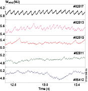
Figure 16. Stored energy versus time of JET-ILW high-δ HT N-seeded discharges in JET-ILW, with for #82817 (2.9/0.9), #85413 (2.5/3.4), #82819 (0.8/0.9), #82811 (2.8/3.6), #85412 (2.6/3.4) with D-fuelling/N-seeding rate between parenthesis in unit 1022 el s−1. Time traces for #85412 and 85413 have been delayed by 3 s for display purpose.
Download figure:
Standard image High-resolution image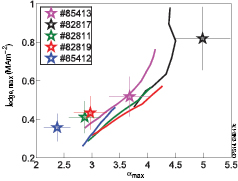
Figure 17. PB stability analysis for N-seeded high-δ HT plasmas in JET-ILW. For all pulses the PB stability is calculated up to n = 50.
Download figure:
Standard image High-resolution image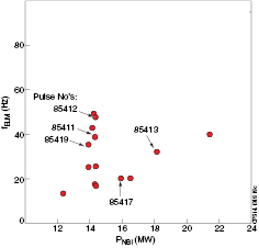
Figure 18. ELM frequency versus neutral beam power for high-δ HT plasma with N-seeding rate above 2 × 10²² el s−1 and fuelling above 0.8 × 10²² el s−1.
Download figure:
Standard image High-resolution imageThe comparison of unseeded and seeded plasmas in the high-δ VT plasmas is even starker; the seeded plasmas have an increased stored energy in relation to the unseeded reference discharges, as illustrated by the stored energy in the time traces in figures 14 and 19. Nevertheless, the ELM characteristic resembles that of type-III ELMs in the WMHD time traces (apart from # 85266, which resembles a more compound type I/III ELM behaviour). This is confirmed by the PB stability analysis as seen in figure 20, as the experimental points in the stability diagram are far removed from the ballooning boundary; another indication that these plasmas are in type-III ELMy H-mode. Unfortunately a large enough variation of the input power is not available in high-δ VT plasmas to obtain further confirmation of the ELM identification with the variation in ELM frequency.
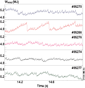
Figure 19. Stored energy versus time of N-seeded high-δ VT plasmas
Download figure:
Standard image High-resolution image
Figure 20. PB stability analysis for N-seeded high-δ VT plasmas in JET-ILW. For all pulses the PB stability is calculated up to n = 50.
Download figure:
Standard image High-resolution image4.4.3. Discussion.
In JET-ILW, it was shown that in unseeded high-δ ELMy H-mode plasmas with either plasma configuration with horizontal (HT) and vertical divertor targets (VT) at 2.5 MA and βN < 1.5, the plasma triangularity has no beneficial effect on the pedestal pressure. Nevertheless for both high-δ configurations, the unseeded plasmas have pedestal pressure gradient likely to be limited by PB stability and are in type-I ELM regime. The stored energy remains low with respect to the type-I ELMy H-mode plasma in JET-C. The low pedestal pressure in the highly fuelled HT and VT plasmas is determined by two factors. First, as mentioned in section 4.1 the low D-gas rate HT plasma features a narrow pedestal. Despite the experimental Jped–αmax point being located close to the corner of the PB diagram (#82585 in figure 13) the narrow pedestal leads to a low pedestal pressure. Second, the widening of the pedestal with increasing D-gas rate does subsequently not increase the pedestal pressure because of the steep slope in the ballooning boundary; as the collisionality of these plasmas is high, only a low bootstrap current can be maintained and the stability boundary is met at reduced pressure gradient αmax. The unseeded high-δ HT and VT plasmas do not simultaneously combine a wide pedestal and accessibility to the corner of the PB diagram across the gas rate scan (note, there is no low D-gas rate high-δ VT plasmas at present).
Seeding nitrogen in JET-ILW plasmas (at 2.5 MA) increases the energy confinement and pedestal pressure in both high-δ HT and VT plasmas. It was shown that N seeding re-establishes the dependence of energy confinement with triangularity for both configurations. Here again, the mechanisms for N seeding to increase pedestal pressure is not known, but it has to be linked to an increase in pedestal temperature—a common feature of the increase in pedestal pressure in high-δ HT and VT plasmas with N seeding. For one of the configuration, the reduction of the ELM energy losses plays an important role in the increase of pedestal pressure with N seeding.
The dependence of ELM energy losses with N seeding can be complex depending on the nitrogen seeding rate and divertor configuration. In the high-δ HT plasmas at 2.5 MA, for a given D-gas rate, the ELM energy losses will first increase (or time scale decrease) as N seeding is raised, with a pedestal that is PB limited and large type-I ELMs at low frequency. At high N seeding rate, the ELM energy losses will decreases down to ~80 kJ and the pedestal become stable with respect to PB instabilities. For the high-δ VT plasmas, as N seeding is increased, the ELM energy losses decrease down to ~50 kJ. The pedestal pressure is not limited by PB instabilities. Key to this difference in ELM energy losses with N seeding is the pedestal density. As nitrogen is seeded, the pedestal density increases in high-δ VT plasmas whereas it decreases in high-δ VT plasmas, most likely linked to the difference in divertor geometry and its effect on neutral recycling. This means that the high-δ HT plasmas are at ne,ped/nGW greater than 0.75 whereas the high-δ VT are at ne,ped/nGW less than 0.6. If the same boundary as in JET-C applied in JET-ILW between type-I and type-III ELM regime in the Te,ped–ne,ped diagram, the high-δ VT plasmas would be in type-III ELM regime and the high-δ HT plasmas in type-I at medium seeding rate and close to type-III ELM regime at high seeding rate, see figure 5.
In section 4.1, it was shown that in unseeded JET-ILW the type-I to type-III transition occurs at much lower pedestal pressure compared to JET-C plasmas. The transition appears at reduced critical pedestal temperature at a Te,ped ~ 0.35 keV for ne,ped/ngw ~ 0.85 instead of Te,ped ~ 0.7 keV for JET-C for a similar value of ne,ped/ngw. This transition is lifted back to increased pedestal temperature when N is seeded. This means that N-seeding increases the critical pedestal temperature for transition from type-I to type-III ELM regime from ~350 eV to above ~700 eV and back to the boundary found in JET-C [12], see figure 5. This new observation is important to understand the confinement of seeded discharges in JET-ILW.
Seeding nitrogen in the high-δ HT plasmas at 2.5 MA in JET-ILW re-establishes the improved pedestal stability at high triangularity plasmas and the corner of the PB stability diagram at increased pressure gradient αmax (figure 17) is accessible in combination with a wide pedestal [16]. Hence a better pedestal and global energy confinement is achieved (WMHD ~ 6 MJ, e.g. #82817). These plasmas feature relatively large type-I ELMs (~150 kJ) for a given D-gas rate and seeding rate. When N seeding rate is further increased, the ELM energy losses decrease and it is likely that a transition occurs from type-I to type-III ELMs with small ELM energy losses; the pedestal is then likely stable with respect to PB instabilities. Nevertheless these plasmas still feature an improved pedestal pressure with respect to the unseeded plasmas; e.g. compare #85412 with WMHD = 5.1 MJ in figure 16 with the pulses in figure 12 with WMHD = 3.5–4 MJ. An improved pedestal pressure at high ne,ped/nGW is once again possible. The seeded high-δ VT plasmas have an improved confinement compared to the unseeded pulses. Unlike the high-δ HT plasmas, this improvement is not due to improved pedestal stability. The pedestal of seeded high-δ VT plasmas has been found to be stable with respect to the PB instabilities. The increase in average pedestal pressure is mostly due to a reduction of ELM energy losses with nitrogen seeding as is seen figures 10 and 11. These seeded plasmas feature small ELMs (down to ~50 kJ) that can be qualitatively identified as type-III ELM.
Experimental observations do point out a dependence on plasma triangularity of the effect of nitrogen seeding on the pedestal and global confinement of ELMy H-mode at βN < 1.5. The physics understanding at play in the increase of pedestal confinement with N seeding have not yet been clearly identified and until so the link between triangularity and effect of nitrogen seeding cannot be proven irrefutably. However, it is likely that more than one effect is at play. Nitrogen seeding re-establishes the improved pedestal stability at high-δ HT plasmas and allow for the corner of the PB stability to be accessible in combination with a wide pedestal. For seeded high-δ VT plasmas, the increase in pedestal pressure and therefore global confinement is due to a reduction of the ELM energy losses (likely type III ELMs) and cannot be explained by the PB stability. Similarly, evidence has now been gathered that the improved pedestal pressure of high triangularity ELMy H-modes in JET-C was possibly linked to the presence of C—an effect that could not have been studied due to the inherent presence of carbon.
These results leads to the paradoxical situation that in the metallic JET-ILW, N-seeded plasma with type-III ELMs have a better confinement and increased pedestal pressure than unseeded JET-ILW plasma in type-I ELM regime at 2.5 MA/2.7 T for high-δ VT and HT plasmas, not unlike results reported in [39]. However, it remains that with N seeding, the pedestal pressure obtained in JET-ILW is not recovered for the same input power at same ne,ped/nGW as in JET-C. Future experiments will need to confirm that a raised power or increased pedestal pressure, the confinement can be raised and high-δ VT seeded plasma in type-I ELM can be obtained in JET-ILW. The high-δ VT plasma do however already offer even with their current global confinement an attractive integrated plasma performance as will be shown in section 6
5. Achievement of stationary plasma conditions
In this section, we discuss the main difficulty we encountered to maintain stationary plasma conditions in the N-seeded high-δ ELMy H-modes and how we succeeded in solving it with application of core deposition of radio-frequency heating.
At the end of the first ILW campaign, it was reported that the N-seeded high-δ HT plasmas had good plasma performance, close the ITER requirements, but plasma conditions were not stationary (tstat/τE~ 6), see figure 15 in [14] and figure 23 for pulse #85413. The electron temperature in the plasma centre (r/a < 0.3) decreases and the sawtooth (ST) eventually disappear. Once the ST have disappeared, the plasmas will disrupt either during the main heating phase or during the plasma termination as is the case for #85413 [40]. The same difficulty is observed in maintaining stationary conditions for high-δ VT plasmas as illustrated in figure 24. The high-δ VT and HT plasmas presented in this paper are in an operational domain where the average W density within the region r/a < 0.8 is not significantly increasing and is in fact low (cW ≤ 3 × 10⁻⁵) and as a result difficult to determine with the standard W analysis techniques [41].
The typical sequence of events responsible for the non-stationary plasma conditions shows the following. The central density peaking increases in time within r/a ~ 0.5 as shown in figures 21 and 23 and at the same time the central temperature decreases, leading to a reduction of ST amplitude, and their eventual loss in the case of the high-δ HT plasmas, see figures 23 and 24. The q-profile has been modified due to a change in resistivity most likely due to an increase of radiation within the ST radius, likely due to W. The W peaking factor can be determined with local parameter R/Lne − 0.5R/LTe as being roughly proportional to a simple analytical estimate of the neoclassical pinch to diffusivity ratio of W (−RV/D) [42]. It is important to note that due to the centrifugal forces (CF) the neoclassical temperature screening is reduced and in fact the peaking factor (−RV/D) is offset to higher values with a more complete calculation [43]. Figure 21 shows that as the electron density peaks, the neoclassical peaking factor RV/D reduces in amplitude and becomes even positive (leading now to a central W peaking). A more accurate calculation would show a change of sign at an earlier time in the discharge. The W concentration in the region inside the ST radius increases and the electron temperature decreases. The ST can still expelled W from the core if of high enough amplitude. Once the ST disappears a really significantly increase in W peaking factor RV/D take place increasing the W flux to the central region with no more process for expelling it. A strong central peaking of W is observed as shown from the soft x-ray (SXR) ratio of measured signal from core to mid-plane line-of-sight, accompanied with dramatic central cooling of the plasma. At this stage, the discharge is usually not recoverable and heading to a disruption [40] mitigated by the massive gas injection system either during the main plasma heating phase or during its termination [40]. The results highlight the fact that it is highly recommended to keep ST in an ELMy H-mode discharge to achieve stationarity conditions even in a case of low W contamination in the main plasma.
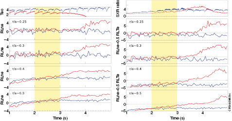
Figure 21. Evolution in time of central core temperature measured with electron cyclotron emission (ECE) heterodyne radiometer, electron density gradient length measured at various r/a, ratio of SXR signal of line-of-sights going through the plasma core to mid-radius, R/Lne − 0.5R/LTe at various central r/a, for 85413 in red and 85412 in blue. X-axis t = 0 is the time of start of neutral beam injection (NBI) heating.
Download figure:
Standard image High-resolution imageSuch a loss of stationary plasma conditions due to density peaking is not specific to the JET-ILW and was already documented in JET-C [44–46] and many other tokamaks. The density profile is determined by the balance between outward turbulent diffusion and inward turbulent and neoclassical convection [47]. It is a well-documented effect that for plasma with density ~0.8 × nGW or above, the neoclassical particle pinch driven by the inductive electric field (Ware pinch) is significant and that the electron density profile will be evolving towards a stationary profile determined by the peaking factor RVware/χPB, with R the major radius, Vware the Ware pinch and χPB the effective heat conductivity assumed proportional to the plasma diffusivity [46]. TRANSP calculations have been done for both the high-δ HT and VT plasmas, with similar results. Here only the results for HT plasmas are reported. TRANSP calculations have shown that for shot #85413, at r/a ~ 0.4, Vware is ~0.02 m s−1 with χPB.~ 0.26 m2 s−1 corresponding to a RVware/χPB ~ −0.25 and of the appropriate magnitude to be responsible for the observed increase in density [47], see figure 22. The effect of electron density peaking due to the Ware pinch can be controlled by addition of central electron heating [48] as was done in #85412 with ~1 W cm−3. The hydrogen minority ion cyclotron resonant heating (ICRH) scenario in dipole strap phasing (42 MHz) was used in a minority concentration X[H] of about 6%. The central heating increased the turbulent transport and therefore turbulent diffusion, χPB is raised from ~0.2 to ~0.5 m2 s−1, Vware stays at the same magnitude but the ratio RVware/χPB is reduced from −0.25 to −0.1 with a resulting normalized gradient length of electron density reduced at r/a ~ 0.4 at 13 s from 1.74 to 0.6. In JET-C, a central heating of 1–2 MW was sufficient to control the density peaking in the high-δ HT plasmas. In JET-ILW, it is necessary to raise the RF heating to 3–5 MW, likely due to the increase radiative power from W in the plasma core, to achieve stationary plasma conditions as shown in figures 23 and 24. The coupling of 4–5 MW to the plasma was made possible with the implementation of a technique using mid-plane localized D-gas injection to improve the antenna-plasma coupling. The details of this technique can be found in 49–51. Although the Ware pinch can only play a non-negligible role on density peaking in high collisionality plasmas, it effects becomes negligible at high temperature required in a fusion reactor [47] and will not apply in ITER.
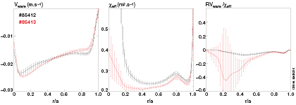
Figure 22. Ware pinch, effective heat conductivity χPB and peaking factor RVwave/χPB calculated with TRANSP for 85412 (black, with RF) and 85413 (red, w/o RF) time-average between 12.5 and 13.5 s.
Download figure:
Standard image High-resolution image
Figure 23. Time trace of N-seeded high-δ HT plasmas discharge #85413 and 85412, (from top to bottom) NBI heating and total radiated power, RF heating power, core and edge density measured by interferometry, electron temperature measured with ECE in the core and at mid-radius, and soft x-ray radiated power measured from the channel crossing the core plasma and one at mid-radius.
Download figure:
Standard image High-resolution image
Figure 24. Time trace of N-seeded high-δ VT plasmas discharge #85266 (blue) and #85267 (red): NBI heating, RF heating power, electron density at plasmacore ne,o (full line) and edge ne,edge (dashed line), central electron temperature and soft x-ray radiated power from channel crossing the core plasma.
Download figure:
Standard image High-resolution imageThe application of RF heating in the plasma centre can control electron density peaking and as a result it is possible to achieve stationary plasma conditions. An understanding was provided for the change of the electron density peaking but not for the change in W transport. The validation of current W transport models against experimental data is an active area of research [42, 43] and has been applied on discharges #85412 and #85413. The turbulent transport is computed with the gyrokinetic code GKW run in its local quasilinear and electrostatic limits. The neoclassical transport is computed with the local drift kinetic code NEO. In both codes, ions, electrons and impurities are all modelled kinetically, with W in the trace limits. At each radial location, the W impurity is modelled in a single average charge state ZW between 24 (edge) and 46 (core) of the coronal equilibrium. More information on how calculations were made can be found in [43]. Figures 25 and 26 show the results of this GKW+NEO calculation for the diffusion and convection coefficients for W, the gradient length of predicted W density and predicted W density profile. It indicates that the W transport is predicted to be governed by neoclassical transport from r/a < 0.4–0.5 and that the turbulent diffusion is dominant outside r/a ~ 0.5. The calculations predict a W density profile, assuming a constant source and constant plasma profiles, that is peaking within r/a < 0.4 in the case without RF (#85413) and hollow in the case with RF (#85412). The additional temperature screening effect from the heated minority in [43] was also investigated but found to have a small effect compared to the difference in density peaking between these plasma pairs. This means that the plasmas were made stationary possibly via three different processes, first by just counteracting the central plasma cooling with the application of heat source, second by the reduction of W source within r/a < 0.4 by the reduction of the density peaking and finally by the change of W transport within the plasma core as a result of the change in density gradient.
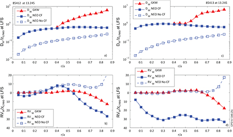
Figure 25. Predicted W transport coefficients at the low field side (LFS), diffusion DW and convection VW coefficients, calculated with GKW+NEO (GKW) for pulse #85412 and #85413 between 13.2 and 13.3 s, with additional simulations with only NEO, with centrifugal force (CF) and without (no CF).
Download figure:
Standard image High-resolution image
Figure 26. Predicted R/Lnw and integrated nw profiles from pulses #85412 and #85413 calculated betweeen 13.2 and 13.3 s, with GKW+NEO (GKW+NEO) with additional simulations with only NEO, with centrifugal force (CF) and without (no CF). A simple analytical estimate of neoclassical peaking (dots) closely follows the neoclassical results without CF effects.
Download figure:
Standard image High-resolution image6. Demonstration of plasma integrated performance at JET
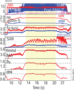
The avoidance of W core accumulation in high-δ N-seeded plasma with VT divertor configuration has successfully been improved by adding at least 3 MW of central ICRH heating power. Long pulse operation with N-seeding was achieved in the VT configuration (less restrictive energy limit) for at least 7 s (figure 27)—where the duration was limited only by the available power. It was possible to extend the plasma duration from tstat/τE ~ 3 to 28. Integrated plasma performance close to the ITER performance were achieved at JET with Be/W PFCs. These stationary ELMy H-mode plasmas are a significant step towards the ITER requirements achieving H98(y,2) ~ 0.85, βN ~ 1.6, <n > /nGW ~ 0.85, Zeff ~ 1.6, tstat/τE ~ 28, ΔWelm/Wped ~ 4% with ΔWelm ~ 65 kJ at 45 Hz (frad ~ 0.55) with very low divertor target power loading and partial detachment between ELMs. Similar results have now been achieved with the JET-ILW to those previously reported with carbon PFCs using radiative ELMy H-mode scenario with N seeding [52].
Figure 27. Time-trace for high-δ VT long N-seeded pulse #85419 at 2.5 MA/2.7 T.
Download figure:
Standard image High-resolution image
7. Summary and conclusion
In conclusion, progress has been made to integrate the ITER-relevant core and edge plasmas within the constraints of an ITER-like wall in JET with its Be wall and W divertor. In JET-ILW, nitrogen seeded high triangularity (high-δ) plasmas at 2.5 MA achieved plasma performance of H98(y,2) ~ 0.85, βN ~ 1.6, <n> /nGW ~ 0.85, Zeff ~ 1.6 with small ELM energy losses about 65 kJ corresponding to 4% of the pedestal stored energy together with partially detached divertor conditions. It was possible to maintain these plasma performances for a duration of 7 s, i.e. 28 times the energy confinement time, with the addition of central radio-frequency heating to control the impurity density peaking and avoid the runway effect of core W accumulation. These plasma performance are close to the desired ITER integrated plasma performance, in terms of Greenwald fraction, Zeff, and divertor conditions but the normalized energy confinement needs to be increased to H98(y,2) = 1 and the ELM energy losses need to be lowered to less than 1% of the pedestal stored energy. It remains to be proven that seeded plasma with partially detached divertor with H98(y,2) ~ 1 and βN ~ 1.8 are achievable at JET. This will be accessible in the next experimental campaign with higher available input power.
In this paper the following was shown:
- For JET-ILW high-δ plasma with both horizontal (HT) and vertical divertor (VT) target, the strike point at the outer divertor is partially detached if the radiative power in the divertor is about 40% of the power flowing through the separatrix. This condition is also applicable in high-δ plasmas with horizontal target in JET-C with intrinsic C seeding.
- The pedestal pressure in unseeded high-δ plasmas for similar input power has decreased from JET-C to JET-ILW by up to 40% (for plasma with horizontal divertor geometry) and the pedestal pressure show no dependence on plasma triangularity for these low βN plasmas. The pedestal of the unseeded high triangularity plasmas is likely to be consistent with PB stability. The PB stability analysis in JET-ILW requires a calculation to higher n-number than in JET-C (n = 50 instead of 30) as the pedestal is cold and at a high collisionality. The low edge current in these plasmas also provide an understanding for the lack of dependence of the pedestal pressure on plasma triangularity, as the corner of the PB diagram cannot be accessed at high D-gas rate. However it is still does not explain what mechanism leads to low pedestal pressure with the change of wall from JET-C to JET-ILW in the unseeded high triangularity plasmas. The current idea being investigated for high triangularity plasmas is that the pedestal structure and stability are affected by a change in fuel recycling and decrease in C content. In other words, the intrinsic C seeding could have been playing a role in the confinement of high triangularity plasmas in JET-C and it could not have been studied due to the inherent presence of C.
- In JET-ILW, nitrogen seeding increases energy confinement via an increase in pedestal pressure and its effect is dependent on the plasma triangularity. This was observed in plasmas both with horizontal (HT) and vertical target (VT) divertor geometry. In plasmas with vertical target divertor geometry, a 40% increase in stored energy is observed with N seeding (no JET-C reference available) with high plasma triangularity against a 15% increase for plasma with low triangularity. The mechanism that leads to an increase of pedestal pressure with nitrogen has not yet been identified but a common feature between the high-δ VT and HT plasmas is the increase of pre-ELM pedestal temperature.
- The dependence of ELM energy losses in N-seeded high-δ plasmas was shown to be complex and to depend on the nitrogen seeding rate, the divertor configuration, and the existence domain of type-I and type-III ELMs. It was possible to access a regime with type-III ELMs with similar plasmas performance for both high-δ HT and VT plasmas (and JET-C high-δ HT plasmas) with detached divertor conditions. At high ne,ped/nGW, the domain of existence of type-I and type-III ELMs (characterized by a critical pedestal temperature Tcrit) [30] for 2.5 MA plasmas is different if the plasma is N-seeded or unseeded. If unseeded, Tcrit is at much lower temperature than in JET-C. With N-seeding, this critical temperature Tcrit is lifted back to its value in JET-C for 2.5 MA plasmas.
- Seeding nitrogen in the high-δ HT plasma in JET-ILW re-established the improved pedestal stability of high triangularity plasmas and the corner of the PB stability is once again accessible. Together with a wide pedestal, this leads to an increase in pedestal pressure. In contrast, the pedestal of the seeded high-δ VT plasmas has been found to be stable with respect to the PB instabilities and the increase in pedestal pressure is not due to improved pedestal stability. It is mostly due to a reduction of the ELM energy losses being in type-III ELMs together with an elevated type-I/III threshold obtained with nitrogen seeding. It is likely that that more than one mechanism is at play and further work will be needed to understand these experimental evidences.
ITER inductive scenario is designed at a triangularity δ ~ 0.4 to benefit from the improved pedestal stability of high triangularity plasma. Some shortcomings in our understanding of the pedestal of high-δ ELMy H-mode have been highlighted by the unexpected decrease in pedestal pressure from JET-ILW to JET-C. It is still unclear if the ITER pedestal will be unstable with respect to the peeling instabilities or the ballooning instabilities [53–55], i.e. in a similar region of the PB diagram as is JET. Experiments on JET need to be conducted to explore the effect of impurity seeding on the pedestal stability and confinement for plasmas that are peeling rather than ballooning limited to broaden the understanding and to expand the extrapolability of the impact of seeding on pedestal confinement towards future fusion devices for low collisionality plasmas. It is also important to identify additional mechanisms leading to an increase of pedestal pressure in the presence of low-Z impurity that may not be related to PB stability.
Acknowledgments
This work was carried out within the framework of the European Fusion Development Agreement. For further information on the contents of this paper please contact publications-officer@jet.efda.org. The views and opinions expressed herein do not necessarily reflect those of the European Commission. This work was also part-funded by the RCUK Energy Programme under grant EP/I501045.