

Abstract
Some interesting phenomena of vortex flows we have found in past experimental research are described. For a given flow configuration, multiple flow patterns can exist and a sudden change from one flow pattern to another can occur. We observed the alternate switching of the flow patterns with irregular periods around a bluff body. The change of vortex flow pattern around a bluff body with geometrical parameters or stratification is not always continuous but often shows a sudden change in the whole flow pattern. Based on our research on vortex flows, an innovative application of the vortex flow to a shrouded wind turbine is made in which the power output of a wind turbine is remarkably enhanced. Unlike the majority of conventional aerodynamic machinery, which tends to minimize vortex shedding, the vortex formation of our 'brimmed' shroud plays an important role in capturing and concentrating wind energy. Furthermore, aerodynamic noise is reduced in this design. The blade tip vortex is weakened by a counter-rotating vortex generated along the inner side of the shroud as they travel downstream, making the shrouded wind turbine much quieter than conventional turbines.
Export citation and abstract BibTeX RIS
Communicated by S Le Dizès
1. Introduction
In general, the flow around an object shows an unsteady and complex vortex shedding at high Reynolds numbers. For the time-averaged flow we usually observe one flow pattern. However, with a certain flow configuration the flow around an object can have multiple flow patterns. This is often called 'critical geometry flow' (Bearman 1980, Ohya 1994). One of the underlying mechanisms is suggested as follows. In such cases, the separated shear layers interact with the trailing edges or some rear portion of an object in a subtle way. This interaction can trigger a drastic change in the flow pattern around the object. As an example of a three-dimensional case, a pair of longitudinal vortices behind a hatchback automobile can drastically change the rear flow for a certain declined angle of the rear hatch (Sovran et al 1978, Hucho 1987). The pair of longitudinal vortices can make a downward flow and the whole flow around a hatchback car tends to be a streamlined body flow; thus the aerodynamic drag is dramatically decreased.
For interior flows, an example could be the flow in a sudden expansion of a pipe which tends to be biased on one side wall due to a feedback flow system. This phenomenon is used as a fluid switch device.
For a typical three-dimensional body, we observed an interesting vortex shedding. If a square plate is placed perpendicular to a uniform flow, it sheds vortices in one of the two fixed wake planes which are parallel with the plate sides. The plane of shedding is switched irregularly from one to the other (Nakamura and Ohya 1986).
From the above point of view of the bluff body flow, we introduce some interesting phenomena of the vortex flows we have found in past experimental research and numerical simulations. Vortex flows around a bluff body show a wide variety of interesting and attractive flow phenomena, because those flows have unsteady and nonlinear features. A very small trigger can induce a large change in the flow pattern around the body, and there might be multiple flow patterns for a flow configuration. The change of vortex flow pattern around a bluff body with geometrical parameters or stratification is not always continuous but often shows a sudden change in the whole flow pattern. In the present paper, we discuss this discontinuity or the discrete nature of the flow pattern in detail, and suggest that there is a common feature for a sudden change in the flow pattern. The flow in reality appears quite chaotic.
For the latter half of this paper, based on those findings, we discuss our innovative application of fluid technologies regarding vortex flows to a new type of shrouded wind turbine. We name the device 'Wind-Lens'. By applying the vortex dynamics to a wind turbine, we successfully improved the output performance of a shrouded wind turbine by a factor of two–five times in power output, compared to conventional wind turbines.
2. Vortex flow phenomena
2.1. Flow around multiple bodies
The flow around multiple bluff bodies is an attractive flow phenomenon, and due to the arrangement—side by side, tandem and staggered—a wide variety of flow patterns appear (Bearman and Wadcock 1973, Zdravcovich 1977). The wake characteristics of groups of normal flat plates, consisting of two, three, or four plates placed side by side with slits in between, have been investigated experimentally in a uniform flow with Reynolds numbers, Re(=Uh/ν) of about (1.3–1.9) × 104 (Hayashi et al 1986, Ohya et al 1989). When the slit ratio s/h (the ratio of slit width to plate width) of a row of flat plates is less than about 2.0, the flows through the slits (gap flows) are biased either upward or downward in a stable way, leading to multiple flow patterns for a single slit ratio value, as shown in figure 1. Some regularities are recognized in the wake characteristics of flat-plate rows such as the gap flow direction and the sequence of flow patterns.

Figure 1. Flow around two plates placed side-by-side with the slit ratio s/h = 0.75.
Download figure:
Standard image High-resolution imageThe plates on the biased side show high drag and regular vortex shedding, while those on the unbiased side show the opposite. The origin of the biased flow has also been investigated with water-tank experiments, numerical calculations and wind tunnel experiments. The results show that the origin of the biasing is strongly related to the vortex shedding of each plate of a row. When the slit ratio is moderate, where each plate of a row can shed vortices, the gap flow is engulfed by the stronger vortices and becomes biased. The stability of biased gap flow appears to be particularly dependent on the behavior of the separated shear layer from the slit side of the plate on the unbiased side.
Thus, for a side-by-side arrangement of bluff cylinders with the same geometrical shape placed in a steady flow, multiple modes of flow pattern exist in the wake. For a two-cylinder arrangement, the gap flow can take two discrete biased directions. For an arrangement of three or more cylinders, the number of wake flow patterns increases rapidly since the resulting flow pattern can be any combination of the two modes from each gap between cylinders.
2.2. Critical geometry flow
2.2.1. Flow around a rectangular cylinder—critical depth
For a rectangular cylinder placed in a smooth flow it is generally reported that with increasing cylinder depth d the base pressure decreases rapidly until a critical minimum is reached, when the depth is slightly greater than about 0.6 times the height, h. This phenomenon has been investigated by many researchers and is referred to as the critical geometry (or the critical depth) for rectangular cylinders (Bearman and Trueman 1972, Bearman 1980). The principal aim of this investigation is to gain a better understanding of the critical phenomenon for a rectangular cylinder (Ohya 1994).
We have examined in detail the time behavior of the mean base pressure for cylinders with d/h = 0.4, 0.5, and 0.6 and have also visualized the flow around cylinders in combination with base pressure measurement in a uniform smooth flow with Reynolds number, Re(=Uh/ν) of (0.67–6.7) × 104. As a result, a cylinder with d/h = 0.5 shows characteristic time variations in base pressure, with alternating high and low values, almost equal to those for d/h = 0.4 and 0.6 (the critical depth), respectively. This is caused by a sudden change in the flow pattern around the cylinder associated with the vortex formation. For cylinders with depths below the critical value, the flow around the cylinder initially changes gradually with increasing d/h, but when d/h reaches a transitional range around d/h = 0.5, there is an abrupt change in the flow pattern.
The mean base pressure variation with side ratio is shown in figure 2. The side ratios around d/h = 0.5 are in a transitional range where the base pressure Cpb has alternating low and high values at irregular intervals, corresponding to the abrupt change between the two different flow patterns. If a mean value over a very long period is considered, it indicates a weighted-average value between the low and high values, which has been reported by many researchers. After the transitional range, at around d/h = 0.6, a stable critical flow pattern is established. In the transitional range, the rate of appearance of the critical flow pattern, i.e., the intermittency, is dependent on the characteristics of the approaching flow, the end plates for a model, the model aspect ratio, the Reynolds number and so on. As to the origin of the critical flow patterns, i.e., the abrupt change in wake pattern to the strong roll-up of the separated shear layers, it appears to be caused by an interaction between the separated shear layers and the body downstream of the separation. The detailed mechanism is expected to be clarified as a result of further research.
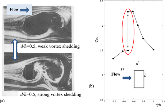
Figure 2. (a) Two flow patterns around a rectangular cylinder with side ratio d/h = 0.5, (b) the corresponding base pressures Cpb versus side ratio d/h.
Download figure:
Standard image High-resolution image2.2.2. Flow around a long flat plate—vortex shedding from flat plates with square leading and trailing edges
Similar irregular switching of wake flow patterns can be observed for a long rectangular plate with the chord-to-thickness ratio, d/h (we call d/h the chord-to-thickness ratio instead of the side ratio in this section) larger than 3 (Cherry et al 1984). This flow phenomenon is categorized as edge-tone flow (Nakamura et al 1991). Vortex shedding from flat plates with square leading and trailing edges with d/h = 3–16 at Reynolds number, Re(=Uh/ν) of (1–3) × 103, is investigated experimentally in a large wind tunnel. It is shown that this vortex shedding is characterized by the impinging-shear-layer instability, where the separated shear layer becomes unstable in the presence of a sharp trailing edge corner. The Strouhal number, Sd (=fd/U), which is based on the plate's chord d, is approximately constant and equal to 0.6 for d/h = 3–5. With increasing ratio, it increases stepwise to values that are approximately equal to integral multiples of 0.6, as shown in figure 3.

Figure 3. Strouhal number Sd based on the chord d versus chord-to-thickness ratio d/h at Re = 103: ◯ ——, experimental (Nakamura et al 1991); ×− · −, numerical (Ohya et al 1992).
Download figure:
Standard image High-resolution imageAfter the wind tunnel test, we tried to clarify the mechanism of the stepwise increase in Strouhal number Sd, using a numerical simulation of DNS (Ohya et al 1992). During an early phase of the numerical investigation, we tried to obtain the response of the flow to some artificial disturbance to check the possibility of controlling the random modulation in the flow arising from the vortex interactions at the trailing edge. This was successful, but we found later that such random modulations can take place spontaneously without introducing any artificial disturbance into the flow. In one such trial on a flat plate with d/h = 8, we found a transition in vortex shedding from m = 2 to m = 3 that was found in a wind tunnel experiment (figure 3). The plate was initially at zero incidence and was then given a small positive incidence of 0.5 for a short time interval t = 616–694, and the subsequent flow development was observed. Figure 4 shows the time history of the lift fluctuation and it can be seen that for t > 1280, the plate experiences very regular vortex shedding with a zero-mean CL value. Figure 4 also shows the corresponding streaklines and the change in the flow pattern corresponding to an irregular shedding (m = 2) and a regular vortex shedding (m = 3). It is interesting to note that the value of Sd is just on the basic line plotted in figure 3.
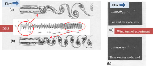
Figure 4. Two flow patterns around a long flat plate with chord-to-thickness ratio d/h = 8. Left: numerical simulation; right: wind tunnel experiment.
Download figure:
Standard image High-resolution imageThus, we can often observe the critical flow pattern switching for bluff bodies with certain geometrical shapes, in which the flow around the body suddenly changes from one mode to another both for short cylinders and long plates. Although the mechanisms for switching flow patterns are different, the flows around rectangle or cylinder with side ratio (or chord-to-thickness ratio) around d/h = 0.5 and 8, show the two different vortex shedding patterns, corresponding to those flow patterns.
2.3. Near wake of a horizontal circular cylinder in stably stratified flows
The near wake of a circular cylinder in linearly stratified flows of finite depth, H, was experimentally investigated by means of flow visualization and measurements of vortex shedding frequencies, at Reynolds numbers, Re(=Ud/ν) of 3.5 × 10³–1.2 × 10⁴ and stratification parameters, kd of 0–2.0. The non-dimensional parameter kd is defined as kd = Nd/U, where N is the Brunt–Väisälä frequency, N2 = −(g/ρ0)(dρ/dz), d, the diameter of the cylinder, and U, the approaching flow velocity. The parameter kd is adopted to quantify the density stratification, and is the inverse of the Froude number.
Experiments were performed in a density-stratified wind tunnel of closed-circuit type. The test section of the wind tunnel was 0.4 m wide, 0.6 m high and 1.7 m long. Designed to generate predefined density-stratified flows, the wind tunnel, except for the contraction and test sections, was divided horizontally into six storeys. A mixture of air and sulfur hexafluoride, SF6, was injected into each storey from an external source to directly produce density stratification. The wind in the test section was generated by 18 microfans, each driven by a micromotor, and three microfans were mounted side-by-side on each storey. The generated wind velocity, U, ranged from 0 to 1.2 m s−1. For homogeneous flow, the wind velocity was set to U = 0.83 m s−1.
Flow around a circular cylinder (d = 10 cm) was observed in a stratified wind field that had a nearly uniform vertical profile of wind velocity and a linear vertical profile of density. With the flow visualization technique, change in the near-wake flow pattern was examined with respect to the stratification parameter, kd. Figure 5 illustrates instantaneous flow patterns. The vortex formation and shedding are significantly enhanced at kd = 0.513 (figure 5(a)) with respect to the homogeneous case. The flow pattern around the circular cylinder suddenly changes in the proximity of kd = 0.52 (figure 5(b)). At this stratification, strong roll-up of the shear layers that have separated from the cylinder is no longer observed, and vortex formation in the wake is highly suppressed. The pattern of the near-wake flow has shifted from a vortex flow pattern to an internal-wave flow pattern (Ohya and Nakamura 1990, 2013).

Figure 5. Sudden change in the flow around a circular cylinder at a certain stability parameter in a stable stratified flow and the hot-wire signal. (a) kd = 0.513, U = 0.7 m s−1, Re = 8100, K = 0.98 (b) kd = 0.521, U = 0.7 m s−1, Re = 8600, K = 1.0 (c) Hot-wire signal corresponding to the change in the flow pattern from (b) to (a).
Download figure:
Standard image High-resolution imageConcurrently with the flow visualization experiments, fluctuating wind velocity measurements were made at the outer edge of the wake of the circular cylinder. From the peak frequency of the wake velocity fluctuations, fv, the Strouhal number, St (=fvd/U) was evaluated for homogeneous and density-stratified flows, as shown in figure 6. With increasing kd, the value of St decreases gradually and becomes approximately 73% of that in homogeneous flow at kd = 0.513. This means that with increasing kd, the vortex shedding from a circular cylinder progressively strengthens, while the Strouhal number gradually becomes lower than that for homogeneous flow. This phenomenon can be explained by the effect of the increasingly stable stratification which enhances the two-dimensionality of the near-wake flow of the circular cylinder; the enhanced two-dimensionality of the flow strengthens the roll-up of the separated shear layer. With further increases in kd, the value of St increases steeply to a large value at around kd = 0.52 (K = 1, explained below) in response to the change in the flow pattern, as shown in figures 5(a) and (b). Thus, for a horizontal circular cylinder placed in a stable stratified flow, we found a sudden change in the flow pattern. This is subjected to the non-dimensional stability parameter consisting of buoyancy force, inertia force and the ratio of the cylinder diameter to fluid depth. In terms of the stratification parameter K(=NH/πU) which includes the depth of stratified flow, H, the critical phenomenon occurs close to K = 1 for all sizes of circular cylinders investigated. The linear theory predicts that lee waves will develop for K > 1. Thus, in this critical phenomenon, the emergence of a stationary lee wave suppresses the vertical fluid motions of the vortices formed behind an object and causes a sudden change in the flow pattern.
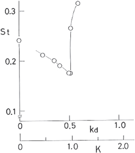
Figure 6. Relationship between the Strouhal number, St, and the stability parameters, kd and K. U = 0.7 m s−1, d = 10 cm (circular cylinder), Re = 5 × 10³–9 × 10³. The value of St at kd = 0 was observed in homogeneous flow (U = 0.83 m s−1, Re = 5800). K is defined as (=NH/πU), H is the fluid depth.
Download figure:
Standard image High-resolution image3. Practical application of vortex dynamics: Wind-Lens turbine
3.1. Introduction
Based on our research on vortex flows described in section 2, an innovative application of vortex flow to a shrouded wind turbine is made in which the power output of a wind turbine is remarkably enhanced. Unlike the majority of conventional aerodynamic machinery, which tends to minimize vortex shedding, the vortex formation of our 'brimmed' shroud plays an important role in capturing and concentrating wind energy. Furthermore, aerodynamic noise is reduced due to the shroud. In section 2, we learned that the flows around a bluff body are strongly affected by the interaction between the separated shear layers and some rear portion of the body and the strong vortex shedding is directly relevant to the uniform separation of the boundary layer. Namely, the enhanced two-dimensionality of the flow strengthens the roll-up of the separated shear layer. This finding is applied to our new wind turbine as described in section 3.2.1.
To help solve energy problems and mitigate global warming the importance of clean, renewable energy is growing. In addition, in order to prevent massive blackouts caused by disasters, small distributed energy systems have been and continue to be tested. In this testing, there has been an increase in the variety of technologies used to generate clean, renewable energy. Of these methods, wind power generation, which can be conducted over the land and ocean, is attracting increasing attention. However, wind power generation has the following disadvantages: a very wide area needed to gain the energy comparable to thermal and nuclear power generation, noise, bird strikes, and landscape disturbances.
Gilbert and Foreman 1983 examined a diffuser-augmented wind turbine (DAWT) as a part of their research on high-power wind turbines. A DAWT is a wind turbine in which the power is augmented by concentrating the wind energy using a diffuser. Their diffuser is a kind of streamlined body and boundary layer separation along the diffuser never occurs. The streamwise section of the diffuser is similar to an airfoil. In contrast to the design of most DAWTs, we have developed a unique wind turbine with a brimmed diffuser called a 'Wind-Lens turbine' (Ohya et al 2008, Ohya and Karasudani 2010). An example of this turbine is shown in figure 7. A Wind-Lens turbine consists of a downwind-type wind turbine and a structure composed of an inlet shroud, a diffuser and a brim. We have applied fluid engineering technologies regarding vortex dynamics to this Wind-Lens turbine, as explained in the following sections.

Figure 7. Schematic of flow around the Wind-Lens turbine.
Download figure:
Standard image High-resolution image3.2. A brimmed diffuser shroud generating strong vortex behind it
The flow which passes inside the diffuser and the flow which comes around behind the brim generate a large vortex behind the structure, as shown in figure 7. As a result of this low-pressure region due to the vortices, air is drawn into the turbine at a higher rate and accelerates more than with a bare wind turbine. Since wind power generation is proportional to the wind speed cubed, this wind acceleration results in a large increase in power output compared to a conventional wind turbine. Due to this effect, a 3 kW turbine with a rotor diameter of 2.5 m generated 2.5 times more power with a compact Wind-Lens than the same turbine without a Wind-Lens in the field experiment, as shown in figure 8.
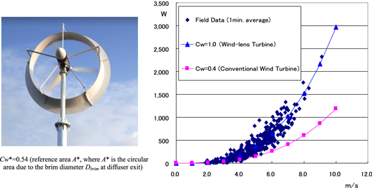
Figure 8. Compact Wind-Lens turbine (rated power of 3 kW at 11 m s−1 wind speed, rotor diameter of 2.5 m) and an example of the field experiment. Cw is the power coefficient based on the rotor swept area A (=power (W)/0.5ρU3A; ρ, air density; U, wind speed (m s−1); W, power (watt) ).
Download figure:
Standard image High-resolution image3.2.1. Application of vortex control plates to a Wind-Lens
In general, the vortex shedding from a three-dimensional body tends to be random and is not uniform in the circumferential direction. Therefore, if a uniform flow separation in the circumferential direction is established in a stable segment in some way, the vortex shedding might be strengthened. Small vortex control plates, which are aligned in the circumferential direction on the Wind-Lens, as shown in figure 9, were attached to strengthen the vortex shedding behind the shroud. As a result, the output performance of the Wind-Lens turbine is further improved. As shown in figure 10, the optimal number of control plates is around 6–12. It should be noted that the spacing between two adjacent control plates corresponds to the correlation length of vortex shedding for a bluff body. In general, the correlation length of vortex shedding of a circular cylinder is reported to be 3–4d , where d is the diameter of a circular cylinder. If we use 6–12 control plates for the Wind-Lens, the spacing in the circumferential direction on the Wind-Lens becomes 3—5dw. Here dw is the projected width of the Wind-Lens from the approaching flow direction. This is why the cases with 6–12 plates show a small increase in power output.

Figure 9. A diffuser shroud (Wind-Lens) with vortex control plates.
Download figure:
Standard image High-resolution image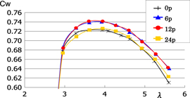
Figure 10. A diffuser shroud with different numbers (0—24) of vortex control plates. The brim height is 5% of the diffuser throat. λ is the tip speed ratio (=rω/U), r, radius of rotor; ω, angular velocity; U, wind speed.
Download figure:
Standard image High-resolution image3.3. Substantial decrease in wind turbine noise
In addition to increased power output, a Wind-Lens turbine offers the following advantages: low noise, reduced risk of bird strikes and reduced landscape disturbance. In this section, we focus on the low aerodynamic noise of Wind-Lens turbines. Figure 11 shows an example of a noise survey based on an international standard for measuring noise generated by wind turbines, JIS C1400-11 (IEC 61400-11). There is no appreciable difference in the noise level between a Wind-Lens turbine in operation and one at rest (Fukuoka City Home Page 2012). There are many sources of wind turbine noise including (1) turbulent boundary layer trailing edge noise; (2) laminar boundary layer vortex shedding noise; (3) boundary layer separation noise; and (4) noise associated with blade tip vortex formation (Morris et al 2004). In particular, blade tip vortices can strongly contribute to aerodynamic noise over a broad band of high frequencies (Arakawa et al 2005, Brooks and Marcolini 1986). We focus on blade tip vortices in a Wind-Lens turbine since the blades are enclosed by the Wind-Lens structure and thus the arrangement of the blade tips in a Wind-Lens turbine is quite different to that of a bare wind turbine.
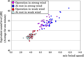
Figure 11. An example of a noise survey for a Wind-Lens turbine (Fukuoka City Home Page 2012).
Download figure:
Standard image High-resolution imageTo clarify the behavior of the blade tip vortices of a wind turbine equipped with a brimmed-diffuser shroud, we conducted a three-dimensional numerical simulation using a large eddy simulation (LES) (Takahashi et al 2012). Since this unique wind turbine consists of not only rotating blades but also a diffuser shroud with a broad-ring brim at the exit periphery, the flow field around the turbine is highly complex and unsteady. In the present numerical analysis, the detailed flow patterns around the rotating blades and the shroud, including the blade tip vortices, were simulated. We used a moving boundary technique in the present CFD simulation to simulate the flow around a rotating blade in order to focus on blade tip vortices.
The simulation results showed a pair of vortices consisting of a blade tip vortex and a counter-rotating vortex which was induced between the blade tip and the inner surface of the diffuser, as shown in figure 12. Since these vortices interacted with each other, the blade tip vortex was weakened by the counter-rotating vortex. Thus, the tip vortex of the Wind-Lens breaks down very rapidly compared with that of the bare wind turbine. The results showed good agreement with previous wind tunnel experiments (Abe et al 2006). In the experiment, mean velocity profiles behind the wind turbines are measured using an x-type hot-wire technique and the tip-vortex structures are detected. As is the case in figure 12, the tip vortices and the induced counter-rotating vortices are shown in figure 13. These two vortices tend to weaken through their interaction. Due to this effect, the strength of the tip vortex for the Wind-Lens turbine becomes weak very rapidly in the downstream region. Such a rapid destruction of the tip vortex may strongly influence the noise reduction of a wind turbine. This is the reason why the Wind-Lens turbine has lower noise than a bare wind turbine.

Figure 12. Simulation results for the Wind-Lens turbine: θ-component of the vorticity inside the turbine. x: inflow direction; r: radial direction; θ: circumferential direction vorticity [1 s−1].
Download figure:
Standard image High-resolution image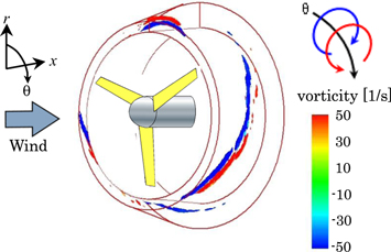
Figure 13. Wind tunnel experimental results for the Wind-Lens using an x-type hot-wire technique : θ-component of the vorticity inside the turbine. x: inflow direction; r: radial direction; θ: circumferential direction vorticity [1 s−1] (Abe et al 2006).
Download figure:
Standard image High-resolution image
4. Conclusions
Some interesting phenomena of the vortex flows were introduced from the bluff body vortex dynamics standpoint. We found that, for a given flow configuration, multiple flow patterns exist. Also, a sudden change in the flow pattern may occur. In these phenomena, we observe the alternate switching of flow patterns with irregular periods. Two important results are:
- (1)Multiple flow patterns with the same shape, the same boundary and initial conditions exist, leading to multiple solutions of the Navier–Stokes equations.
- (2)Sudden change in the flow pattern demonstrates the existence of critical geometry and critical flow condition.
These cases have in common that, for certain values of the governing parameters (geometrical aspect ratios, stratification), one observes more than one asymptotic flow solution, which leads to a discontinuous variation of flow structure when varying these parameters. All these flows involve separated shear layers and vortex shedding.
Based on our research on the vortex flows, an innovative application of the vortex flow to a shrouded wind turbine is discussed. Unlike the majority of conventional aerodynamic machineries which tends to minimize vortex shedding, the vortex formation of our 'brimmed' shroud plays an important role. This new downwind-type wind turbine (Wind-Lens turbine) has a shroud composed of an inlet, a diffuser, and a brim. The design is a result of a set of fluid engineering technologies and vortex dynamics. A key factor is the brim placed at the exit periphery of the diffuser shroud to intentionally form a vortex shedding behind the turbine. The low-pressure region due to the strong vortex formation behind the brim draws more mass flow to the wind turbine inside the diffuser.
The brim is a three-dimensional body as a ring structure. The vortex shedding from the brim is sometimes weakened by the flow fluctuation in the circumferential direction of the ring. If we put small separating plates (called vortex control plates) aligned in the circumferential direction of a brimmed diffuser with a specific spacing, the vortex shedding in each defined segment is strengthened. Consequently, the stronger vortex shedding of a Wind-Lens due to the vortex control plates increases the output power enhancement.
In addition, the Wind-Lens turbine is much quieter than any conventional wind turbine due to the reduction of tip vortices. Our LES simulations show a pair of vortices consisting of a blade tip vortex and a counter-rotating vortex generated between the blade tip and the inner surface of the diffuser. The blade tip vortex is weakened by the counter-rotating vortex as they propagate downstream. The results show good agreement with previous wind tunnel experiments. Since the main origin of aerodynamic noise is considerably weakened, the shroud wind turbine is quiet.
Acknowledgment
This study was partially supported by Ministry of the Environment and Ministry of the Education, Culture, Sports and Science (MEXT), Japan. We gratefully acknowledge our colleagues, professors T Karasudani and T Uchida, research associate Dr T Nagai, technical staff K Watanabe and K Sugitani, of Kyushu University. We also would like to acknowledge the kind cooperation of the city of Fukuoka.