


ABSTRACT
The Spitzer-Cosmic Assembly Deep Near-infrared Extragalactic Legacy Survey (S-CANDELS; PI G.Fazio) is a Cycle 8 Exploration Program designed to detect galaxies at very high redshifts (). To mitigate the effects of cosmic variance and also to take advantage of deep coextensive coverage in multiple bands by the Hubble Space Telescope (HST) Multi-cycle Treasury Program CANDELS, S-CANDELS was carried out within five widely separated extragalactic fields: the UKIDSS Ultra-deep Survey, the Extended Chandra Deep Field South, COSMOS, the HST Deep Field North, and the Extended Groth Strip. S-CANDELS builds upon the existing coverage of these fields from the Spitzer Extended Deep Survey (SEDS), a Cycle 6 Exploration Program, by increasing the integration time from SEDS' 12 hr to a total of 50 hr but within a smaller area, 0.16 deg2. The additional depth significantly increases the survey completeness at faint magnitudes. This paper describes the S-CANDELS survey design, processing, and publicly available data products. We present Infrared Array Camera (IRAC) dual-band catalogs reaching to a depth of 26.5 AB mag. Deep IRAC counts for the roughly 135,000 galaxies detected by S-CANDELS are consistent with models based on known galaxy populations. The increase in depth beyond earlier Spitzer/IRAC surveys does not reveal a significant additional contribution from discrete sources to the diffuse Cosmic Infrared Background (CIB). Thus it remains true that only roughly half of the estimated CIB flux from COBE/DIRBE is resolved.


1. INTRODUCTION
Deep imaging at infrared wavelengths is now a standard tool for detecting and identifying galaxies at the highest redshifts (e.g., Finkelstein et al. 2013; Oesch et al. 2013). Indeed, deep infrared surveys carried out in the low-background conditions prevailing in space are indispensable for reliable detections of the most distant objects. Moreover, observations carried out in the infrared regime benefit from their sensitivity to rest-frame stellar light, relatively free from attenuation by dust. Thus space-based infrared observations have a demonstrated capability to detect distant galaxies and characterize their stellar content.
The Infrared Array Camera (IRAC; Fazio et al. 2004a) aboard the Spitzer Space Telescope (Werner et al. 2004) has made significant additions to our knowledge of high-redshift galaxies. Although Hubble Space Telescope (HST) observations have been essential for identifying candidate high-redshift galaxies using the Lyman-break technique (e.g., Steidel et al. 1996a, 1996b), infrared imaging by IRAC, particularly in its 3.6 and 4.5 μm bandpasses, has proved essential for confirming the high-redshift nature of these objects and for understanding the physical processes within them. IRAC data enable photometric redshift measurements and constrain stellar masses, ages, and star formation histories. IRAC has revealed, for example, that high-redshift galaxies were suprisingly massive ( ) and had appreciable stellar ages (200–300 Myr), permitting new estimates of the star formation rate in the early universe (; e.g., Egami et al. 2005; Eyles et al. 2005; Yan et al. 2005, 2006, 2014; Labbé et al. 2006, 2007, 2010, 2013; Stark et al. 2007).


The successes of deep surveys played a major role in motivating the HST Multi-cycle Treasury Program known as the Cosmic Assembly Deep Near-infrared Extragalactic Legacy Survey (CANDELS), which used the Wide-field Camera 3 (WFC3) to deeply cover five premier extragalactic survey fields both deeply and with high spatial resolution in the YJH bands (Grogin et al. 2011; Koekemoer et al. 2011). CANDELS also obtained roughly coextensive Advanced Camera for Surveys (ACS) parallel imaging at visible wavelengths. All the CANDELS fields were also covered by IRAC at 3.6 and 4.5 μm by the Spitzer Extended Deep Survey (SEDS; Ashby et al. 2013a), to furnish rest-frame visible-light detections of the most distant objects detected by CANDELS. Compared to CANDELS, SEDS covered a relatively wide area (1.46 deg2 versus 0.16 deg2). However, although SEDS is quite deep by current survey standards (26 AB mag, 3σ), it is not well-suited to detect the faintest, most distant CANDELS sources. For this reason our team has carried out a much deeper IRAC survey focused specifically on the CANDELS fields. The new observations were obtained as a Spitzer Cycle 8 Exploration Program called Spitzer-CANDELS (S-CANDELS; PI G.Fazio). S-CANDELS achieved a total exposure time of 50 hr in all CANDELS fields at both 3.6 and 4.5 μm. Figure 1 shows how S-CANDELS compares to the other major Spitzer surveys in terms of depth and coverage.

Figure 1. Comparison of measured S-CANDELS 3.6 μm 1σ depth and total area (solid square) to other major Spitzer /IRAC extragalactic surveys from the cyrogenic mission (circles) and warm mission (squares). The points shown for S-CANDELS, SEDS (Ashby et al. 2013a), SDWFS (Ashby et al. 2009), and SSDF (Ashby et al. 2013b) are based on photometry of simulated sources in mosaic images and therefore account for source confusion. All other points are taken from the online calculator SENS-PET, using the appropriate sensitivies for the cryogenic and warm mission. Low-background conditions were assumed throughout except for SpIES, for which a medium background was (conservatively) assumed. Surveys shown include Great Observatories Origins Deep Survey (GOODS; Giavalisco et al. 2004; Wang et al. 2010; Hathi et al. 2012; Lin et al. 2012), the Extended Groth Strip (EGS; Davis et al. 2007; Bielby et al. 2012), Extended Chandra Deep Field South (E-CDFS; Rix et al. 2004; Castellano et al. 2010), Spitzer Public Legacy Survey of UKIDSS Ultra-deep Survey (SpUDS; Caputi et al. 2011), SCOSMOS (Spitzer Deep Survey of HST COSMOS 2-Degree ACS Field; Scoville et al. 2007a), Spitzer Extragalactic Representative Volume Survey (SERVS; Mauduit et al. 2012), Blanco Cluster Survey (BCS), Spitzer Wide-area Infrared Extragalactic Survey (SWIRE; Lonsdale et al. 2003, 2004), the Spitzer First Look Survey (FLS; Fang et al. 2004), the Ultra-deep Field (UDF; Labbé et al. 2013), the Spitzer IRAC/MUSYC Public Legacy in E-CDFS (SIMPLE; Damen et al. 2011), Spitzer-IRAC Equatorial Survey (SpIES), and Spitzer Large-area Survey with Hyper-Suprime-Cam (SPLASH). Compared to the analogous Figure 1 of Ashby et al. (2013a), SpIES, SSDF, SERVS, and S-CANDELS have all been updated because they relied on SENS-PET estimates that did not yet account for the slightly reduced sensitivity of IRAC during the warm mission.
Download figure:
Standard image High-resolution imageThis paper documents and characterizes the S-CANDELS mosaics, which are being publically released, and compares the results with SEDS. These objectives require using substantially the same methods as for SEDS. In particular, we use only the IRAC data for source identification and photometry. Other groups within the CANDELS collaboration are using the higher-resolution imaging from HST/WFC3 F160W as a prior for source identification (Section 6). These efforts include Galametz et al. (2013; for the Ultra-deep Survey; UDS) Guo et al. (2013; ECDFS), H. Nayyeri et al. 2015, in preparation (COSMOS), G. Barro et al. 2015, in preparation (HDFN), and M. Stefanon et al. 2015, in preparation (Extended Groth Strip; EGS). Of these, most make use of the full-mission S-CANDELS mosaics created as described below. Galametz et al. (2013) and Guo et al. (2013) used the original SEDS data from Ashby et al. (2013a). Our independence from other data sets also has the advantage of detecting extremely red sources that are invisible at shorter wavelengths, like those either thought to be at very high redshifts, or to have extreme attenuation by dust. Such sources exist and are being investigated (M. Stefanon et al. 2015, in preparation).
This paper is organized as follows. Section 2 presents the observations; Section 2.1 describes the individual S-CANDELS fields. Section 3 discusses the details of the S-CANDELS source identification, photometry, and validation. The results are described in Section 4. Section 5 describes the SEDS catalogs. Finally, Section 6 summarizes the benefits of the 50 hr S-CANDELS depth and describes some uses of the data. All magnitudes given in this paper are in the AB system.
2. OBSERVATIONS AND DATA REDUCTION
2.1. The Five S-CANDELS Survey Fields
Because the scientific emphasis of S-CANDELS is on detecting and characterizing galaxies at very high redshifts, it is vital that the S-CANDELS fields be placed where sensitive photometry is available in multiple bands other than the IRAC 3.6 and 4.5 μm filters. Near-infrared (NIR) and visible imaging deep enough to match the IRAC observations reported here are of special importance. Accordingly, we chose to locate S-CANDELS inside the wider and shallower fields already covered by SEDS, in regions that enjoy deep optical and NIR imaging from HST/CANDELS. These S-CANDELS fields are thus the Extended GOODS-south (aka the GEMS field, hereafter ECDFS; Rix et al. 2004; Castellano et al. 2010), the Extended GOODS-north (HDFN; Giavalisco et al. 2004; Wang et al. 2010; Hathi et al. 2012; Lin et al. 2012), the UKIDSS UDS (aka the Subaru/XMM Deep Field, Ouchi et al. 2001; Lawrence et al. 2007), a narrow field within the EGS (Davis et al. 2007; Bielby et al. 2012), and a strip within the UltraVista deep survey of the larger COSMOS field (Scoville et al. 2007b; McCracken et al. 2012). These five S-CANDELS fields are distributed in ecliptic longitude and declination to permit ground-based followup from both hemispheres.
The depths, areas, and sensitivity of earlier IRAC coverage of the five S-CANDELS fields up to and including the SEDS campaigns are described by Ashby et al. (2013a). The S-CANDELS observations were of a similar character, but had a different etendue. Figure 2 shows the cumulative depth versus area plots for S-CANDELS, which had a design depth of 50 hr.

Figure 2. Cumulative area coverage as a function of exposure time for S-CANDELS, including other, earlier observations (Table 1). The solid and dotted lines correspond, respectively, to the 3.6 and 4.5 μm bands. Panel (f) shows the coverage summed over all five S-CANDELS fields. The nominal S-CANDELS depth was 50 hr.
Download figure:
Standard image High-resolution image2.2. Mapping Strategy
The S-CANDELS observing strategy was designed to maximize the area covered to full depth within the CANDELS area. Each field was visited twice7 with six months separating the two visits. Table 1 lists the epochs for each field. All of the IRAC full-depth coverage is within the SEDS area (Ashby et al. 2013a), and almost all is within the area covered by HST for CANDELS. (See Figures 3–12.)


Figure 3. Full-depth S-CANDELS 3.6 μm mosaic in the UDS field, including exposures from the cryogenic mission and SEDS. The image stretch ranges from −0.01 (white) to 0.05 MJy sr−1 (black). The minimum total exposure time in the field shown is 12 hr. The black polygons indicate where the total IRAC integration reaches 50 hr. The six-sided black polygons in the field center enclose regions where the coverage grades down to the 12 hr SEDS depth. The red and blue rectangles respectively indicate the extent of the HST/WFC3 and ACS imaging from CANDELS (Grogin et al. 2011; Koekemoer et al. 2011).
Download figure:
Standard image High-resolution image
Figure 4. Same as Figure 3, but showing the S-CANDELS 4.5 μm mosaic of the UDS. The stretch ranges from −0.01 to 0.05 MJy sr−1.
Download figure:
Standard image High-resolution image
Figure 5. Full-depth SCANDELS 3.6 μm mosaic of the ECDFS. The stretch ranges from −0.01 to 0.05 MJy sr−1. The black polygon encloses a region where the depth of coverage is a minimum of 50 hr. The red rectangle indicates the portion of the field covered by the HST CANDELS and ERS programs.
Download figure:
Standard image High-resolution image
Figure 6. Same as Figure 5, but showing the full-depth 4.5 μm mosaic of the ECDFS including all SEDS and cryogenic imaging by IRAC. The stretch ranges from −0.01 to 0.05 MJy sr−1.
Download figure:
Standard image High-resolution image
Figure 7. Total S-CANDELS 3.6 μm mosaic in the COSMOS field including all observations from SEDS and the cryogenic mission (Table 1). The image stretch ranges from −0.01 (white) to 0.05 MJy sr−1 (black). The black polygon approximately indicates the area covered by at least 50 hr of integration time. All of the field shown is covered by at least 12 hr total integration time. The red line encloses the region covered by the CANDELS WFC3 observations, and the blue line encloses the region observed by the CANDELS parallel ACS exposures.
Download figure:
Standard image High-resolution image
Figure 8. Same as Figure 7, but showing the full-depth 4.5 μm mosaic in the COSMOS field. The stretch ranges from −0.01 to 0.05 MJy sr−1.
Download figure:
Standard image High-resolution image
Figure 9. Total SCANDELS IRAC 3.6 μm mosaic in the HDFN. The black polygon indicates approximately where the total 3.6 μm integration time, which includes observations from the cryogenic mission (i.e., GOODS), rises to at least 50 hr. The magenta rectangle indicates the coextensive HST/WFC3+ACS footprint from CANDELS. The stretch ranges from −0.01 to 0.05 MJy sr−1.
Download figure:
Standard image High-resolution image
Figure 10. As Figure 9, but for the 4.5 μm observations. The stretch ranges from −0.01 to 0.05 MJy sr−1.
Download figure:
Standard image High-resolution image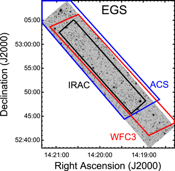
Figure 11. Total S-CANDELS 3.6 μm mosaic of the EGS field. The deepest coverage, at least 50 hr total integration time, lies within the black rectangle. The stretch ranges from −0.01 to 0.05 MJy sr−1. Outside the black rectangle the 3.6 μm integration time is at least 12 hr. The blue and red polygons respectively indicate the approximate locations of the CANDELS ACS and WFC3 coverage.
Download figure:
Standard image High-resolution image
Figure 12. Same as Figure 11, but for the total S-CANDELS 4.5 μm mosaic of the EGS field. The stretch ranges from −0.01 to 0.05 MJy sr−1.
Download figure:
Standard image High-resolution image
Figure 13. Illustration of StarFinder source extraction. These negative images show a region of the 3.6 μm S-CANDELS ECDFS mosaic; the other S-CANDELS band and fields behave in a similar way. The linear stretch ranges from −0.001 (white) to 0.004 MJy sr−1 (black) throughout. Top: the IRAC 3.6 μm mosaic created by IRACProc. Red circles are placed around sources with AB magnitudes as shown. Center: the corresponding StarFinder model image. Bottom: the residual image obtained after the detected sources are removed.

Download figure:
Standard image High-resolution imageTable 1. The Five S-CANDELS Fields
| Field | PIDa | Epoch | BCDs Used | Pipeline |
|---|---|---|---|---|
| 3.6 μm, 4.5 μm | Version | |||
| UDS (2:18:00, −5:10:17; area = 0.035,0.034 deg2) | ||||
| 181 | 2004 Jul 27–28 | 548, 597b | S18.7.0 | |
| 40021 | 2008 Jan 26–29 | 3640, 3457 | " | |
| 61041 | 2009 Sep 8–23 | 5255, 5256 | S18.18.0 | |
| 61041 | 2010 Feb 13–Mar 2 | 5328, 5328 | " | |
| 61041 | 2010 Sep 22–Oct 13 | 5436, 5436 | " | |
| 80218 | 2012 Feb 29–Mar 11 | 4680, 4680 | S19.1.0 | |
| 80218 | 2012 Oct 11–Oct 29 | 5328, 5328 | " | |
| 80218 | 2013 Mar 16 | 648, 648 | " | |
| ECDFS (3:32:20, −27:37:20; area = 0.049, 0.054 deg2) | ||||
| 81 | 2004 Feb 16 | 167, 146 | S18.7.0 | |
| 194 | 2004 Feb 8–16 | 1724, 1723c | " | |
| 194 | 2004 Aug 12–18 | 1632, 1632c | " | |
| 20708 | 2005 Aug 19–23 | 1943, 1872 | " | |
| 20708 | 2006 Feb 6–11 | 1899, 1944 | " | |
| 30866 | 2007 Feb 15 | 1200, 1080 | " | |
| 60022 | 2010 Sep 20–Oct 4 | 4752, 4588 | S18.18.0 | |
| 70145 | 2010 Sep 16–Oct 25 | 3510, 3510 | " | |
| 70145 | 2011 Feb 11–Apr 7 | 4140, 4140 | " | |
| 70145 | 2011 Sep 21–Sep 22 | 630, 630 | " | |
| 70204 | 2011 Mar 17–Apr 7 | 5184, 5128 | " | |
| 60022 | 2011 Mar 26–Apr 7 | 4596, 4752 | " | |
| 80217 | 2011 Sep 25–Sep 28 | 1944, 1944 | S19.1.0 | |
| 60022 | 2011 Oct 10–Oct 20 | 4717, 4552 | " | |
| 80217 | 2012 Mar 30–Apr 5 | 1944, 1943 | " | |
| COSMOS (10:00:30, +2:10:00; area = 0.034, 0.034 deg2) | ||||
| 20070 | 2005 Dec 30–2006 Jan 2 | 1259, 1253 | S18.7.0 | |
| 61043 | 2010 Jan 25–Feb 4 | 3672, 3672 | S18.18.0 | |
| 61043 | 2010 Jun 10–28 | 3164, 3140 | " | |
| 61043 | 2011 Jan 30–Feb 6 | 3180, 3196 | " | |
| 80057 | 2012 Feb 4–Feb 19 | 6840, 6840 | S19.1.0 | |
| 80057 | 2012 Jun 26–Jul 9 | 6840, 6840 | " | |
| HDFN (12:36:12, +62:14:12; area = 0.019,0.020 deg2) | ||||
| 81 | 2004 May 26–27 | 215, 178 | S18.7.0 | |
| 169 | 2004 May 16–26 | 2609, 2609c | " | |
| 169 | 2004 Nov 17–25 | 2447, 2447c | " | |
| 169 | 2005 Nov 25 | 114, 114c | " | |
| 20218 | 2005 Nov 28–Dec 9 | 200, 200 | " | |
| 20218 | 2006 Jun 2–3 | 200, 200 | " | |
| 61040 | 2010 May 12-29 | 4895, 4896 | S18.18.0 | |
| 61040 | 2011 Feb 28–Mar 13 | 5440, 5440 | " | |
| 60140 | 2011 May 22–Jun 2 | 5208, 4896 | " | |
| 80215 | 2012 Jan 25–28 | 1872, 1872 | S19.1.0 | |
| 80215 | 2012 Jul 23–30 | 1944, 1944 | " | |
| EGS (14:19:38, +52:25:47; area = 0.021, 0.021 deg2) | ||||
| 8 | 2003 Dec 21–28 | 988, 969c | S18.7.0 | |
| 8 | 2004 Jun 28–Jul 3 | 1027, 989c | " | |
| 8 | 2006 Mar 28–29 | 117, 24c | " | |
| 41023 | 2008 Jan 24–25 | 726, 726 | " | |
| 41023 | 2008 Jul 21–23 | 726, 726 | " | |
| 61042 | 2010 Feb 5–16 | 4056, 4056 | S18.18.0 | |
| 61042 | 2010 Aug 4–19 | 4021, 4056 | " | |
| 61042 | 2011 Feb 10–22 | 3970, 4048 | " | |
| 80216 | 2011 Aug 18–21 | 2052, 2052 | S19.1.0 | |
| 80216 | 2012 Feb 2–26 | 3888, 3888 | " | |
| 80216 | 2012 Aug 28–31 | 1836, 1836 | " | |
Notes. S-CANDELS field positions and areas. Areas given were covered respectively at 3.6 and 4.5 μm to a depth of at least 50 hr total integration time by the combined sum of all programs listed here. Compare to Table 3.
aSpitzer Program Identification Number. b30 s frames. c200 s frames.Download table as: ASCIITypeset image
Each of the two observation epochs accumulated 19 hr integration time per pointing, or less when a field had pre-existing coverage other than SEDS. For efficiency, each position in the field was usually observed for 2 frames of 100 s each before moving the telescope to the next position. The medium Reuleaux 36 dither pattern was used throughout, except for the EGS field, which used an 18-point dither pattern.8 The AORs thus sampled each sky position at many positions on the arrays. Each AOR (pair of linked AORs for the EGS) covered the full intended field of view for one wavelength, but the 3.6 and 4.5 μm coverage did not overlap for UDS, HDFN, or CDFS. For COSMOS and EGS, the overlap was only partial. However, the IRAC fields of view switch places every six months, so the area observed at 3.6 μm in one epoch was observed at 4.5 μm in the alternate epoch and vice versa to achieve complete coverage of the intended area at both wavelengths.
2.3. Data Reduction
We used the same procedures to reduce the S-CANDELS data as were applied earlier to the SEDS observations described by Ashby et al. (2013a). In the following we therefore describe only the most important aspects of the S-CANDELS reductions.
All suitable data were combined into full-mission mosaics that include coextensive imaging from SEDS and other projects from both the cryogenic and warm missions (see Table 1 for the complete lists) into full-mission mosaics covering the CANDELS fields. Processing was based on IRAC Corrected Basic Calibrated Data exposures generated by the pipeline versions indicated in Table 1. The different pipeline versions differ only in matters of minor artifact correction, not in overall calibration9 of the 3.6 or 4.5 μm exposures.
Before mosaicking, all the IRAC exposures were corrected for long-term residual images and for column pulldown. The mosaics were constructed with IRACproc (Schuster et al. 2006) in the same way as was done for SEDS, but over narrower fields. In the ECDFS and the HDFN, which have very large datasets, computer memory constraints prevented us from making the mosaics in a single IRACproc run. For these fields we mosaicked subsets of the exposures and subsequently mean-averaged the results into a single mosaic. As with SEDS, all the S-CANDELS mosaics were pixellated to 0 6 and were aligned to the tangent-plane projections used by the CANDELS team (Table 5 of Koekemoer et al. 2011). Figure 3 through 12 show the final IRAC mosaics for all five fields.
The final mosaics, coverage maps, model images, and residual images are all available from the Spitzer Exploration Science Programs website.10
3. SOURCE EXTRACTION AND PHOTOMETRY
3.1. Source Identification
Source confusion is pronounced even for the 12 hr SEDS mosaics; the problem impacts the deeper S-CANDELS mosaics even more strongly. We therefore used StarFinder (ver.1.6f; Diolaiti et al. 2000) to identify sources because StarFinder is optimized for identification and photometry of heavily blended sources in crowded fields (e.g., globular cluster stars). As was done for SEDS, the S-CANDELS catalogs were constructed in two steps. First, StarFinder was used to identify and locate sources (even faint, blended ones). Second, a custom code was used to correct biases in the StarFinder photometry.
The source-identification step was performed on the full-depth S-CANDELS mosaics. StarFinder implements an algorithm based on iterated fitting and subtracting of a template point-spread function (PSF) image. Because the S-CANDELS mosaics are small and heavily confused, we were unable to identify enough isolated, sufficiently bright point sources to construct useful PSFs template images from the S-CANDELS mosaics themselves. Instead, we used the PSF template images constructed earlier for SEDS. Because the fields were observed at similar roll angles for both SEDS and S-CANDELS, this should not introduce significant error. StarFinder is capable of repeating the source-identification algorithm using the residuals it generates from a first pass through the mosaics. This allows the code to refine (reduce) its estimate of the background noise in the absence of the brightest objects. We therefore configured StarFinder to process each field three times, as was done for SEDS, with identical parameter settings. In particular, the software was not allowed to deblend sources closer together than 09, roughly half the FWHM of the PSF in the two warm IRAC passbands. Based on our inspections of the final (third-pass) residual images (Figure 13 shows an example), we judged this approach successful. The residual images are manifestly free of large-scale background artifacts, and the faint sources (which are all effectively point sources) are well-fitted by our approach.
As was done for SEDS, the aperture magnitudes for each source were measured after re-inserting its fitted PSF at its fitted position in the StarFinder residual image and then measuring background-subtracted fluxes interior to diameters of 24, 36, 48, 60, 72, and 120. Thus the S-CANDELS aperture magnitudes are relatively free of contamination by nearby neighbors (because to a good approximation they have been subtracted off) of both the photometered source and the nearby background. The S-CANDELS catalogs contain both the PSF-fitted magnitudes based on the iterative procedure described above and the aperture magnitudes. Because we used the same PSF templates and photometric apertures as SEDS, we also used the same SEDS photometric corrections to correct the original, PSF-fitted magnitudes to total magnitudes. All S-CANDELS catalogs include these aperture corrections, which are given by Ashby et al. (2013; their Table 2). To avoid spurious sources, only objects detected in both bands were included in the catalogs.
Table 2. Completeness in the S-CANDELS IRAC Catalogs
| AB Mag | UDS | ECDFS | COSMOS | HDFN | EGS |
|---|---|---|---|---|---|
| 18.25 | 0.998 ± 0.016 | 1.000 ± 0.019 | 0.997 ± 0.015 | 0.997 ± 0.015 | 0.996 ± 0.020 |
| 18.75 | 0.994 ± 0.015 | 0.996 ± 0.017 | 0.995 ± 0.013 | 0.995 ± 0.014 | 0.997 ± 0.019 |
| 19.25 | 0.990 ± 0.011 | 0.996 ± 0.017 | 0.991 ± 0.011 | 0.990 ± 0.011 | 0.992 ± 0.011 |
| 19.75 | 0.987 ± 0.011 | 0.988 ± 0.016 | 0.984 ± 0.010 | 0.982 ± 0.011 | 0.987 ± 0.011 |
| 20.25 | 0.976 ± 0.011 | 0.982 ± 0.014 | 0.975 ± 0.010 | 0.971 ± 0.011 | 0.975 ± 0.011 |
| 20.75 | 0.962 ± 0.010 | 0.974 ± 0.013 | 0.961 ± 0.010 | 0.960 ± 0.010 | 0.964 ± 0.011 |
| 21.25 | 0.955 ± 0.010 | 0.963 ± 0.011 | 0.950 ± 0.010 | 0.943 ± 0.010 | 0.948 ± 0.011 |
| 21.75 | 0.933 ± 0.013 | 0.949 ± 0.015 | 0.929 ± 0.013 | 0.920 ± 0.013 | 0.926 ± 0.012 |
| 22.25 | 0.903 ± 0.012 | 0.921 ± 0.016 | 0.896 ± 0.012 | 0.897 ± 0.013 | 0.900 ± 0.011 |
| 22.75 | 0.871 ± 0.012 | 0.908 ± 0.016 | 0.869 ± 0.010 | 0.862 ± 0.020 | 0.870 ± 0.010 |
| 23.25 | 0.818 ± 0.015 | 0.849 ± 0.015 | 0.822 ± 0.010 | 0.805 ± 0.022 | 0.824 ± 0.015 |
| 23.75 | 0.751 ± 0.015 | 0.800 ± 0.014 | 0.757 ± 0.010 | 0.731 ± 0.021 | 0.753 ± 0.014 |
| 24.25 | 0.668 ± 0.014 | 0.738 ± 0.009 | 0.678 ± 0.009 | 0.649 ± 0.011 | 0.668 ± 0.013 |
| 24.75 | 0.533 ± 0.012 | 0.649 ± 0.009 | 0.570 ± 0.008 | 0.533 ± 0.009 | 0.572 ± 0.012 |
| 25.25 | 0.331 ± 0.010 | 0.525 ± 0.009 | 0.420 ± 0.007 | 0.393 ± 0.008 | 0.427 ± 0.011 |
| 25.75 | 0.090 ± 0.005 | 0.348 ± 0.007 | 0.215 ± 0.005 | 0.213 ± 0.006 | 0.221 ± 0.008 |
| 26.25 | 0.012 ± 0.002 | 0.140 ± 0.004 | 0.048 ± 0.002 | 0.071 ± 0.003 | 0.054 ± 0.004 |
| 26.75 | 0.001 ± 0.000 | 0.018 ± 0.002 | 0.009 ± 0.002 | 0.007 ± 0.001 | 0.005 ± 0.001 |
| 27.25 | 0.000 ± 0.000 | 0.001 ± 0.000 | 0.001 ± 0.001 | 0.000 ± 0.000 | 0.000 ± 0.000 |
Note. Completeness estimates for the S-CANDELS fields. The magnitudes correspond to the centers of bins of width 0.5 mag in which the completeness was estimated. The completeness is unity at brighter magnitudes than those listed. These completeness estimates were made for sources detected in both IRAC bands.
Download table as: ASCIITypeset image
The completeness and reliability of S-CANDELS were assessed on a field-by-field basis with the standard Monte Carlo approach, identical to that used for SEDS (Ashby et al. 2013a). SEDS established, by matching CANDELS F160W sources to IRAC-detected objects in COSMOS, that all IRAC sources fainter than 23 AB mag are point sources at IRAC resolution. This is true even for a majority of IRAC sources brighter than 23 AB mag. We therefore used only point sources in our completeness and depth simulations. We simultaneously inserted simulated sources in both the 3.6 and 4.5 μm mosaics at identical locations. For simplicity, the simulated sources were created with [3.6]−[4.5] = 0, i.e., no attempt was made to insert sources with a range of colors. After the S-CANDELS mosaics had been modified by inserting simulated sources, source identification and photometry was performed in exactly the same way as for the unmodified mosaics. The completeness and magnitude bias were assessed by comparing the results to the a priori known input sources over the range of magnitudes seen for the real sources. The results are given in Table 2 and shown in Figure 14.

Figure 14. Completeness in the S-CANDELS fields estimated by Monte Carlo simulations as described in Section 3.1. Symbols indicate the completeness measured in bins of width 0.5 mag within the S-CANDELS fields shown in Figures 3–12 where the depth of coverage was at least 12 hr; the mean coverage was by design signficantly higher (Figure 2). The completeness measured for SEDS, specifically coverage of at least 10 ks total exposure time in the wider-but-shallower SEDS mosaics from Ashby et al. (2013a), is indicated with the black line. In both cases the values given are by-field averages. The completeness in any particular small region depends on the actual integration time achieved there and on the highly variable local source confusion.
Download figure:
Standard image High-resolution imageS-CANDELS completeness is identical to that of SEDS for sources brighter than about 24.5 AB mag. For sources fainter than 24.5 mag, however, S-CANDELS is significantly more complete than SEDS, recovering a larger but flux-dependent fraction of the simulated sources. The improvement relative to SEDS ranges up to a factor of several, depending on the specific field and source magnitude. Taken at face value, S-CANDELS reaches 50% completeness at roughly [3.6] = [4.5] = 25 mag in all fields except the ECDFS, where (because of the additional coverage from the ERS and IUDF programs), the 50% completeness threshold is reached at 25.3 mag. Users of S-CANDELS data are cautioned that these are generalizations; the depths are variable across the S-CANDELS fields, and the completeness at any one location is a strong function of both the local source density and the total exposure time.
As with SEDS, the S-CANDELS estimates of photometric error and bias were also based solely on the artificial source simulations, in order to account for the impact of source confusion in these very deep mosaics. The photometric uncertainties and biases are given respectively in Tables 3 and 4 for each of the S-CANDELS fields, and are shown in Figure 15. The S-CANDELS photometric uncertainties are very close to those measured in the shallower SEDS mosaics (Figure 27 of Ashby et al. 2013a). This is discussed in Section 4.2.

Figure 15. S-CANDELS measurement errors based on photometry of simulated sources as described in Section 3.1. The symbols indicate the measurement bias as a function of apparent magnitude. Positive values indicate that measured values are brighter than the true values. The S-CANDELS catalogs have been corrected for this bias. The solid and dashed lines indicate the 1σ measurement uncertainty at 3.6 and 4.5 μm, respectively. The lower limit of 0.03 mag on the measurement uncertainties reflects the uncertainty in the IRAC absolute calibration.
Download figure:
Standard image High-resolution imageTable 3. Empirical Photometric Uncertainties for S-CANDELS
| AB Mag | UDS | ECDFS | COSMOS | HDFN | EGS |
|---|---|---|---|---|---|
| 3.6 μm | |||||
| 16.25 | 0.03 | 0.03 | 0.03 | 0.03 | 0.03 |
| 16.75 | 0.03 | 0.03 | 0.03 | 0.03 | 0.03 |
| 17.25 | 0.03 | 0.03 | 0.03 | 0.03 | 0.03 |
| 17.75 | 0.03 | 0.03 | 0.03 | 0.03 | 0.03 |
| 18.25 | 0.06 | 0.05 | 0.06 | 0.06 | 0.06 |
| 18.75 | 0.06 | 0.06 | 0.06 | 0.07 | 0.06 |
| 19.25 | 0.07 | 0.06 | 0.07 | 0.07 | 0.07 |
| 19.75 | 0.08 | 0.06 | 0.08 | 0.08 | 0.07 |
| 20.25 | 0.08 | 0.07 | 0.08 | 0.09 | 0.08 |
| 20.75 | 0.09 | 0.08 | 0.08 | 0.09 | 0.09 |
| 21.25 | 0.10 | 0.09 | 0.10 | 0.10 | 0.10 |
| 21.75 | 0.11 | 0.10 | 0.11 | 0.11 | 0.11 |
| 22.25 | 0.12 | 0.11 | 0.12 | 0.12 | 0.12 |
| 22.75 | 0.14 | 0.13 | 0.14 | 0.14 | 0.13 |
| 23.25 | 0.15 | 0.14 | 0.15 | 0.15 | 0.15 |
| 23.75 | 0.18 | 0.17 | 0.18 | 0.19 | 0.18 |
| 24.25 | 0.21 | 0.20 | 0.21 | 0.22 | 0.22 |
| 24.75 | 0.24 | 0.22 | 0.24 | 0.24 | 0.24 |
| 25.25 | 0.30 | 0.26 | 0.28 | 0.28 | 0.28 |
| 25.75 | 0.33 | 0.31 | 0.32 | 0.33 | 0.33 |
| 26.25 | 0.35 | 0.34 | 0.36 | 0.35 | 0.36 |
| 4.5 μm | |||||
| 16.25 | 0.03 | 0.03 | 0.03 | 0.03 | 0.03 |
| 16.75 | 0.03 | 0.03 | 0.03 | 0.03 | 0.03 |
| 17.25 | 0.03 | 0.03 | 0.03 | 0.03 | 0.03 |
| 17.75 | 0.03 | 0.03 | 0.03 | 0.03 | 0.03 |
| 18.25 | 0.06 | 0.05 | 0.05 | 0.05 | 0.05 |
| 18.75 | 0.05 | 0.06 | 0.05 | 0.06 | 0.06 |
| 19.25 | 0.07 | 0.06 | 0.07 | 0.06 | 0.06 |
| 19.75 | 0.07 | 0.06 | 0.08 | 0.07 | 0.07 |
| 20.25 | 0.08 | 0.07 | 0.08 | 0.08 | 0.08 |
| 20.75 | 0.09 | 0.08 | 0.09 | 0.09 | 0.08 |
| 21.25 | 0.09 | 0.08 | 0.10 | 0.09 | 0.09 |
| 21.75 | 0.10 | 0.09 | 0.11 | 0.10 | 0.10 |
| 22.25 | 0.11 | 0.11 | 0.12 | 0.11 | 0.12 |
| 22.75 | 0.13 | 0.12 | 0.13 | 0.12 | 0.13 |
| 23.25 | 0.14 | 0.14 | 0.14 | 0.14 | 0.14 |
| 23.75 | 0.18 | 0.16 | 0.18 | 0.16 | 0.17 |
| 24.25 | 0.21 | 0.20 | 0.21 | 0.21 | 0.20 |
| 24.75 | 0.24 | 0.22 | 0.23 | 0.23 | 0.23 |
| 25.25 | 0.29 | 0.26 | 0.28 | 0.27 | 0.27 |
| 25.75 | 0.34 | 0.30 | 0.32 | 0.31 | 0.32 |
| 26.25 | 0.34 | 0.33 | 0.34 | 0.35 | 0.34 |
Note. Empirically determined S-CANDELS 1σ photometric uncertainties (magnitudes) determined using the Monte Carlo simulations described in Section 3.1. An estimated 3% systematic error in the IRAC flux calibration is included and limits the uncertainties for bright sources. Sources brighter than 14.7 AB mag are saturated in S-CANDELS.
Download table as: ASCIITypeset image
As with SEDS, the measurement bias is relatively small for sources brighter than the 50% completeness limit but grows rapidly at progressively fainter magnitudes (Table 4). This appears to confirm an interpretation in which faint sources are increasingly difficult to deblend from their neighbors. The contamination of the photometric apertures by imperfectly subtracted brighter neighbors affects the photometry even though the measurements were made in source-subtracted residual images. The S-CANDELS catalogs have been corrected to remove the resulting average magnitude bias.
Table 4. Photometric Bias in S-CANDELS Catalogs
| Mag | UDS | ECDFS | COSMOS | HDFN | EGS |
|---|---|---|---|---|---|
| 3.6 μm | |||||
| 17.75 | 0.00 | 0.00 | 0.00 | 0.00 | 0.00 |
| 18.25 | 0.01 | 0.00 | 0.00 | 0.01 | 0.00 |
| 18.75 | 0.01 | 0.00 | 0.00 | 0.01 | 0.00 |
| 19.25 | 0.01 | 0.01 | 0.01 | 0.01 | 0.00 |
| 19.75 | 0.01 | 0.01 | 0.01 | 0.01 | 0.00 |
| 20.25 | 0.01 | 0.01 | 0.01 | 0.01 | 0.01 |
| 20.75 | 0.02 | 0.01 | 0.01 | 0.02 | 0.01 |
| 21.25 | 0.02 | 0.01 | 0.01 | 0.02 | 0.01 |
| 21.75 | 0.02 | 0.01 | 0.02 | 0.02 | 0.01 |
| 22.25 | 0.03 | 0.02 | 0.02 | 0.03 | 0.02 |
| 22.75 | 0.03 | 0.02 | 0.02 | 0.03 | 0.02 |
| 23.25 | 0.04 | 0.02 | 0.02 | 0.03 | 0.03 |
| 23.75 | 0.06 | 0.03 | 0.03 | 0.05 | 0.04 |
| 24.25 | 0.07 | 0.04 | 0.04 | 0.06 | 0.06 |
| 24.75 | 0.08 | 0.04 | 0.04 | 0.07 | 0.08 |
| 25.25 | 0.13 | 0.06 | 0.05 | 0.09 | 0.08 |
| 25.75 | 0.17 | 0.08 | 0.10 | 0.13 | 0.12 |
| 26.25 | 0.31 | 0.11 | 0.18 | 0.20 | 0.19 |
| 4.5 μm | |||||
| 18.75 | 0.00 | 0.00 | 0.00 | 0.00 | 0.00 |
| 19.25 | 0.01 | 0.00 | 0.01 | 0.01 | 0.00 |
| 19.75 | 0.01 | 0.01 | 0.01 | 0.01 | 0.00 |
| 20.25 | 0.01 | 0.01 | 0.01 | 0.01 | 0.00 |
| 20.75 | 0.01 | 0.01 | 0.01 | 0.01 | 0.00 |
| 21.25 | 0.01 | 0.01 | 0.01 | 0.01 | 0.00 |
| 21.75 | 0.02 | 0.01 | 0.02 | 0.01 | 0.00 |
| 22.25 | 0.02 | 0.01 | 0.02 | 0.02 | 0.01 |
| 22.75 | 0.02 | 0.02 | 0.02 | 0.02 | 0.01 |
| 23.25 | 0.03 | 0.02 | 0.02 | 0.02 | 0.01 |
| 23.75 | 0.04 | 0.02 | 0.03 | 0.03 | 0.02 |
| 24.25 | 0.05 | 0.03 | 0.04 | 0.04 | 0.03 |
| 24.75 | 0.06 | 0.04 | 0.05 | 0.05 | 0.04 |
| 25.25 | 0.09 | 0.06 | 0.06 | 0.07 | 0.07 |
| 25.75 | 0.19 | 0.08 | 0.11 | 0.09 | 0.11 |
| 26.25 | 0.38 | 0.13 | 0.22 | 0.18 | 0.21 |
Note. Mean photometric bias in the S-CANDELS fields (magnitudes), determined empirically using the Monte Carlo simulations described in Section 3.1. The bias is zero for sources brighter than the brightest magnitude listed in the table. The sense of the bias is that artificial sources are measured to be brighter, on average, than they were a priori known to be, by the amounts listed. These biases have already been corrected in the catalogs presented here.
Download table as: ASCIITypeset image
3.2. Photometric Validation
We verified our astrometry by comparing the positions of extracted sources to their counterparts in the references used by the CANDELS team. We also compared to the bright sources in the Two Micron All Sky Survey (Skrutskie et al. 2006). The results are shown in Table 5. The S-CANDELS astrometry is consistent with previous work in the five CANDELS fields. The scatter measured for the positions of sources on the IRAC and non-IRAC catalogs is of order 02, which is also consistent with analogous measurements carried out in other fields, e.g., SEDS, the SSDF (Ashby et al. 2013b), and SDWFS (Ashby et al. 2009).
Table 5. S-CANDELS Astrometric Offsets
| Field | ΔR.A. | ΔDecl. | Total | Coordinate |
|---|---|---|---|---|
| (arcsec) | (arcsec) | (arcsec) | Reference | |
| Relative to CANDELS | ||||
| UDS | 0.00 ± 0.13 | −0.02 ± 0.14 | 0.14 ± 0.10 | UKIDSS DR8 (Lawrence et al. 2007) |
| ECDFS | 0.02 ± 0.16 | −0.19 ± 0.15 | 0.27 ± 0.10 | GOODS r2.0 z (Giavalisco et al. 2004) |
| COSMOS | 0.02 ± 0.15 | 0.04 ± 0.16 | 0.19 ± 0.11 | COSMOS v2.0 (Koekemoer et al. 2007) |
| HDFN | 0.12 ± 0.27 | 0.01 ± 0.19 | 0.30 ± 0.17 | GOODS r2.0 z (Giavalisco et al. 2004) |
| EGS | 0.03 ± 0.14 | −0.02 ± 0.16 | 0.19 ± 0.20 | Lotz et al. (2008) |
| Relative to 2MASS | ||||
| UDS | 0.00 ± 0.18 | −0.03 ± 0.19 | 0.23 ± 0.12 | Skrutskie et al. (2006) |
| ECDFS | −0.01 ± 0.16 | 0.03 ± 0.18 | 0.22 ± 0.11 | " |
| COSMOS | −0.02 ± 0.17 | 0.00 ± 0.17 | 0.22 ± 0.11 | " |
| HDFN | −0.03 ± 0.16 | 0.00 ± 0.16 | 0.20 ± 0.11 | " |
| EGS | 0.03 ± 0.18 | 0.00 ± 0.16 | 0.21 ± 0.12 | " |
Note. Mean coordinate offsets measured for S-CANDELS relative to astrometric references. The upper half of the Table compares the S-CANDELS IRAC source positions to the astrometric references adopted by CANDELS. The bottom half of the Table compares the S-CANDELS source positions to 2MASS. Total offsets refer to the mean absolute offsets. The stated uncertainties are the standard deviations of the offset distributions for matched sources.
Download table as: ASCIITypeset image
We verified our photometry by comparing to the measurements obtained earlier in the shallower SEDS campaign, which were themselves already validated against S-COSMOS (Sanders et al. 2007), SpUDS (version DR2), the EGS (Barmby et al. 2008), and SIMPLE (Damen et al. 2011).
To verify the S-CANDELS flux calibration, we matched the S-CANDELS catalogs to those from SEDS. In all cases, the matching was done using a search radius, i.e., roughly twice the S-CANDELS astrometric uncertainty and one-third the IRAC PSFs' FWHMs. Only SEDS sources brighter than 26 AB mag (the SEDS 3σ detection limit) were used for the comparison. Sources close to saturation (<15.4 mag in 200 s exposures) were excluded. The results are shown in Figure 16.


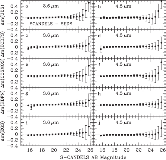
Figure 16. Comparison of S-CANDELS and SEDS photometry at 3.6 and 4.5 μm. Symbols indicate the mean differences for measurements made in 24 diameter apertures within bins 0.5 mag wide. Positive-valued differences mean sources appear brighter in SEDS than in S-CANDELS on average. All error bars are 1σ. Vertical dotted lines indicate the SEDS 3σ sensitivity limits. The comparison was made after both photometric datasets were corrected to total magnitudes by compensating for empirically determined aperture losses and biases.
Download figure:
Standard image High-resolution imageFor sources brighter than 25 mag in all fields, S-CANDELS photometry agrees very well with SEDS. There are a few exceptions. In HDFN three of seven sources in the [3.6] = (16.0,16.5) bin differ by ∼0.2 mag from SEDS, and two of five sources in the brightest 4.5 μm ECDFS bin are discrepant at a similar level. All of the discrepant sources are bright point sources (Milky Way stars). The S-CANDELS photometry in the complementary IRAC band for these sources agrees with that from SEDS (Figure 16). Variability is therefore unlikely to be the issue. All discrepant sources lie in parts of the mosaics that combine SEDS and S-CANDELS exposures, and moreover the S-CANDELS residual images for these sources are markedly different than those from SEDS. This suggests that although the PSF fitting technique worked for the vast majority of S-CANDELS sources, it failed for these few objects, for reasons particular to the details of their immediate surroundings and the mechanics of StarFinder.
The photometry for faint sources follows a more consistent pattern. Over a wide magnitude range in both SCANDELS bands the agreement between SCANDELS and SEDS is excellent. In all five fields, however, as the SEDS 26 mag sensitivity limit is approached, a bias becomes apparent in the sense that SEDS sources are systematically brighter than their S-CANDELS counterparts. The bias is lowest overall in the HDFN (∼0.1 mag), and highest in the UDS (∼0.5 mag).
To better understand the reason for the faint-source bias, we inspected both the SEDS and S-CANDELS data (mosaics and catalogs) at the locations of the most problematic sources, i.e., those with discrepancies greater than 0.5 mag. Apart from a tendency—by no means universal—to lie in the outskirts of bright sources, the discrepant sources present no obvious common trait in the residual images. They do not lie in regions with obvious background artifacts. Indeed, the S-CANDELS and SEDS photometry of neighbors within of discrepant sources agree within the uncertainties, with very few exceptions. The discrepancies are therefore not attributable to issues with the background modeling. The vast majority of discrepant sources also have the same number of neighbors within in both SEDS and S-CANDELS. The problem therefore does not generally arise from the StarFinder deblending procedure; the same numbers of sources lie in the peripheries of the discrepant sources in both SEDS and S-CANDELS. Finally, we compared the coordinate offsets of matched SEDS and S-CANDELS sources. We found no evidence to suggest that the most discrepant sources were significantly spatially offset in SEDS and S-CANDELS, relative to sources with consistent photometry. Inappropriate placement of the StarFinder PSF centroids and apertures is therefore not likely to be the problem.


Having ruled out issues with offset coordinates, poor background estimation, and deblending of different numbers of neighbors, we tentatively attribute the faint-source bias to flux boosting by very-low-level cosmic rays that are not efficiently rejected at SEDS depths. With the factor-of-four greater number of exposures available to S-CANDELS, there is statistical power to reject faint outliers that cannot be ruled out at SEDS depths. This hypothesis is consistent with the fact that the bias is seen to be most pronounced in the faintest two SEDS magnitude bins, and is of roughly the same size as the SEDS uncertainties themselves. The S-CANDELS magnitudes show similar bias but only for sources roughly 0.5 mag fainter than for SEDS, so we cannot rule out an analogous effect in the faintest S-CANDELS bins (cf. Table 4, Ashby et al. 2013a, Table 5).
4. DISCUSSION
4.1. Number Counts
S-CANDELS detects roughly 135,000 sources in the combined 0.16 deg2 area covered by the five fields in the survey. Figures 17 and 18 and Table 6 present the resulting differential source counts along with Milky Way star counts estimated from the Arendt et al. (1998) model for the S-CANDELS lines of sight.

Figure 17. Differential 3.6 μm counts in the five S-CANDELS fields. Open symbols show the raw counts, while solid symbols indicate the counts corrected for incompleteness on the basis of simulated detections as described in Section 3.1. Error bars represent the Poisson statistics only in panels (a)–(e). The solid red lines in panels (d) and (e) indicate the incompleteness-corrected counts measured in the HDFN by Magdis et al. (2008) and in the EGS by Fazio et al. (2004b), respectively. The dotted lines in panels (a)–(e) show the expected counts arising from Milky Way stars, based on the DIRBE Faint Source Model at 3.5 μm (Wainscoat et al. 1992; Cohen et al. 1993, 1994, 1995; Arendt et al. 1998). Panel (f) shows the area-weighted mean counts for all of S-CANDELS together with predicted counts from Helgason et al. (2012). The upper and lower blue dotted lines indicate the Helgason et al. high-faint-end and low-faint-end luminosity function models, i.e., models in which the slopes of the faint end of the luminosity functions were respectively set to and −0.8. The middle blue dashed line indicates the so-called "default" model, obtained by averaging the high-faint-end and low-faint-end models. The SEDS source counts are shown in red.

Download figure:
Standard image High-resolution image
Figure 18. Differential counts in the five S-CANDELS fields at 4.5 μm. The meanings of the symbols are the same as in Figure 17. The Milky Way Star Models shown are those for DIRBE at 4.9 μm, from Arendt et al. (1998), Wainscoat et al. (1992), and Cohen et al. (1993, 1994, 1995).
Download figure:
Standard image High-resolution imageTable 6. S-CANDELS IRAC Number Counts
| Mag | UDS | ECDFS | COSMOS | HDFN | EGS | Total | ||||||
|---|---|---|---|---|---|---|---|---|---|---|---|---|
| (AB) | Counts | Unc. | Counts | Unc. | Counts | Unc. | Counts | Unc. | Counts | Unc. | Counts | Unc. |
| 3.6 μm | ||||||||||||
| 14.75 | 1.77 | 0.71 | 1.88 | 0.71 | 2.09 | 0.50 | 2.14 | 0.58 | 1.90 | 0.71 | 1.95 | 0.15 |
| 15.25 | 1.77 | 0.71 | 2.06 | 0.58 | 2.33 | 0.38 | 2.26 | 0.50 | 1.90 | 0.71 | 2.10 | 0.24 |
| 15.75 | 1.47 | 1.00 | 2.06 | 0.58 | 2.49 | 0.32 | 2.26 | 0.50 | 1.60 | 1.00 | 2.13 | 0.46 |
| 16.25 | 2.08 | 0.50 | 2.36 | 0.41 | 2.49 | 0.32 | 2.26 | 0.50 | 2.20 | 0.50 | 2.31 | 0.16 |
| 16.75 | 2.51 | 0.30 | 2.06 | 0.58 | 2.39 | 0.35 | 2.14 | 0.58 | 2.50 | 0.35 | 2.34 | 0.21 |
| 17.25 | 2.65 | 0.26 | 2.69 | 0.28 | 2.81 | 0.22 | 2.44 | 0.41 | 2.50 | 0.35 | 2.67 | 0.16 |
| 17.75 | 2.87 | 0.20 | 2.73 | 0.27 | 2.92 | 0.19 | 2.74 | 0.29 | 2.50 | 0.35 | 2.79 | 0.17 |
| 18.25 | 3.04 | 0.17 | 3.04 | 0.19 | 3.10 | 0.16 | 3.02 | 0.21 | 3.00 | 0.20 | 3.05 | 0.04 |
| 18.75 | 3.38 | 0.11 | 3.46 | 0.12 | 3.57 | 0.09 | 3.51 | 0.12 | 3.48 | 0.12 | 3.48 | 0.07 |
| 19.25 | 3.73 | 0.08 | 3.70 | 0.09 | 3.84 | 0.07 | 3.87 | 0.08 | 3.81 | 0.08 | 3.78 | 0.07 |
| 19.75 | 3.92 | 0.06 | 3.94 | 0.07 | 4.06 | 0.05 | 4.03 | 0.07 | 3.98 | 0.07 | 3.98 | 0.06 |
| 20.25 | 4.10 | 0.05 | 4.09 | 0.06 | 4.20 | 0.05 | 4.17 | 0.06 | 4.12 | 0.06 | 4.13 | 0.05 |
| 20.75 | 4.26 | 0.04 | 4.20 | 0.05 | 4.29 | 0.04 | 4.29 | 0.05 | 4.27 | 0.05 | 4.25 | 0.04 |
| 21.25 | 4.32 | 0.04 | 4.33 | 0.04 | 4.42 | 0.04 | 4.41 | 0.04 | 4.41 | 0.04 | 4.37 | 0.05 |
| 21.75 | 4.45 | 0.04 | 4.42 | 0.04 | 4.52 | 0.04 | 4.50 | 0.04 | 4.49 | 0.04 | 4.47 | 0.04 |
| 22.25 | 4.57 | 0.03 | 4.55 | 0.04 | 4.59 | 0.03 | 4.59 | 0.04 | 4.58 | 0.04 | 4.57 | 0.02 |
| 22.75 | 4.69 | 0.03 | 4.67 | 0.03 | 4.69 | 0.03 | 4.73 | 0.04 | 4.73 | 0.03 | 4.69 | 0.03 |
| 23.25 | 4.79 | 0.03 | 4.77 | 0.03 | 4.79 | 0.03 | 4.80 | 0.04 | 4.83 | 0.03 | 4.79 | 0.03 |
| 23.75 | 4.89 | 0.03 | 4.90 | 0.03 | 4.91 | 0.03 | 4.92 | 0.04 | 4.93 | 0.03 | 4.90 | 0.02 |
| 24.25 | 4.99 | 0.03 | 4.98 | 0.03 | 4.99 | 0.03 | 5.01 | 0.03 | 5.05 | 0.03 | 5.00 | 0.03 |
| 24.75 | 5.03 | 0.03 | 5.06 | 0.03 | 5.06 | 0.03 | 5.08 | 0.03 | 5.13 | 0.03 | 5.06 | 0.04 |
| 25.25 | 5.07 | 0.04 | 5.11 | 0.03 | 5.08 | 0.03 | 5.14 | 0.04 | 5.19 | 0.04 | 5.11 | 0.05 |
| 25.75 | 5.30 | 0.07 | 5.09 | 0.04 | 5.15 | 0.04 | 5.19 | 0.05 | 5.22 | 0.05 | 5.18 | 0.08 |
| 26.25 | 5.52 | 0.18 | 5.09 | 0.06 | 5.45 | 0.07 | 5.25 | 0.08 | 5.44 | 0.09 | 5.36 | 0.18 |
| 26.75 | 5.86 | 1.44 | 5.28 | 0.14 | 5.52 | 0.24 | 5.56 | 0.23 | 5.76 | 0.28 | 5.61 | 0.22 |
| 4.5 μm | ||||||||||||
| 14.75 | ⋯ | ⋯ | ⋯ | ⋯ | 1.97 | 0.58 | ⋯ | ⋯ | 1.90 | 0.71 | 1.92 | 0.14 |
| 15.25 | 1.77 | 0.71 | 1.58 | 1.00 | 1.79 | 0.71 | 2.14 | 0.58 | 1.90 | 0.71 | 1.81 | 0.21 |
| 15.75 | 1.95 | 0.58 | 1.88 | 0.71 | 2.44 | 0.33 | 2.14 | 0.58 | 1.90 | 0.71 | 2.11 | 0.24 |
| 16.25 | 1.47 | 1.00 | 2.36 | 0.41 | 2.44 | 0.33 | ⋯ | ⋯ | 1.60 | 1.00 | 2.21 | 0.50 |
| 16.75 | 2.25 | 0.41 | 2.48 | 0.35 | 2.33 | 0.38 | 1.96 | 0.71 | 2.20 | 0.50 | 2.32 | 0.21 |
| 17.25 | 2.51 | 0.30 | 2.53 | 0.33 | 2.49 | 0.32 | 2.36 | 0.45 | 2.56 | 0.33 | 2.50 | 0.08 |
| 17.75 | 2.83 | 0.21 | 2.69 | 0.28 | 3.02 | 0.17 | 2.62 | 0.33 | 2.45 | 0.38 | 2.79 | 0.23 |
| 18.25 | 2.85 | 0.20 | 2.92 | 0.21 | 3.00 | 0.18 | 2.78 | 0.28 | 2.93 | 0.22 | 2.91 | 0.08 |
| 18.75 | 3.29 | 0.12 | 3.21 | 0.15 | 3.37 | 0.12 | 3.30 | 0.15 | 3.24 | 0.15 | 3.28 | 0.06 |
| 19.25 | 3.58 | 0.09 | 3.64 | 0.10 | 3.70 | 0.08 | 3.60 | 0.11 | 3.70 | 0.09 | 3.64 | 0.06 |
| 19.75 | 3.90 | 0.06 | 3.91 | 0.07 | 4.00 | 0.06 | 4.00 | 0.07 | 3.93 | 0.07 | 3.94 | 0.05 |
| 20.25 | 4.14 | 0.05 | 4.13 | 0.06 | 4.20 | 0.05 | 4.11 | 0.06 | 4.17 | 0.05 | 4.15 | 0.04 |
| 20.75 | 4.27 | 0.04 | 4.27 | 0.05 | 4.33 | 0.04 | 4.31 | 0.05 | 4.28 | 0.05 | 4.29 | 0.03 |
| 21.25 | 4.37 | 0.04 | 4.40 | 0.04 | 4.42 | 0.04 | 4.37 | 0.05 | 4.39 | 0.04 | 4.39 | 0.02 |
| 21.75 | 4.46 | 0.04 | 4.49 | 0.04 | 4.50 | 0.04 | 4.48 | 0.04 | 4.49 | 0.04 | 4.48 | 0.02 |
| 22.25 | 4.59 | 0.03 | 4.57 | 0.04 | 4.59 | 0.03 | 4.53 | 0.04 | 4.57 | 0.04 | 4.57 | 0.02 |
| 22.75 | 4.68 | 0.03 | 4.68 | 0.03 | 4.66 | 0.03 | 4.68 | 0.04 | 4.68 | 0.03 | 4.67 | 0.01 |
| 23.25 | 4.78 | 0.03 | 4.81 | 0.03 | 4.78 | 0.03 | 4.77 | 0.04 | 4.82 | 0.03 | 4.79 | 0.02 |
| 23.75 | 4.89 | 0.03 | 4.92 | 0.03 | 4.87 | 0.03 | 4.88 | 0.04 | 4.91 | 0.03 | 4.89 | 0.02 |
| 24.25 | 4.99 | 0.03 | 5.00 | 0.03 | 4.96 | 0.03 | 4.99 | 0.03 | 5.03 | 0.03 | 4.99 | 0.02 |
| 24.75 | 5.08 | 0.03 | 5.10 | 0.03 | 5.07 | 0.03 | 5.08 | 0.03 | 5.11 | 0.03 | 5.09 | 0.02 |
| 25.25 | 5.13 | 0.04 | 5.16 | 0.03 | 5.12 | 0.03 | 5.16 | 0.04 | 5.20 | 0.04 | 5.15 | 0.03 |
| 25.75 | 5.39 | 0.07 | 5.23 | 0.03 | 5.23 | 0.04 | 5.29 | 0.04 | 5.30 | 0.04 | 5.28 | 0.07 |
| 26.25 | 5.43 | 0.19 | 5.38 | 0.05 | 5.55 | 0.07 | 5.52 | 0.07 | 5.60 | 0.08 | 5.48 | 0.09 |
| 26.75 | ⋯ | ⋯ | 5.44 | 0.12 | 5.37 | 0.25 | 5.75 | 0.21 | 5.71 | 0.28 | 5.63 | 0.21 |
Note. Differential number counts measured for S-CANDELS measured in bins of width 0.5 mag, expressed in terms of mag−1 deg−2. Counts given as "Total" are area-weighted means derived from all five S-CANDELS fields using the areas given in Table 1. All uncertainties are 1σ. The errors given for individual fields reflect only counting errors, but the uncertainties attributed to "Total" counts also take field-field variations into account.


Download table as: ASCIITypeset image
The S-CANDELS counts rely on completeness corrections that are based on simulated sources with zero color, i.e., . At faint levels they could therefore in principle suffer from subtle systematic effects, because real sources span a range of colors (Figure 19). Our simulations do not fully account for faint, blue 3.6 μm sources, which would tend to elude detection in the 4.5 μm band. Faint, red 4.5 μm sources would be under-counted for the same reason. However, these systematic effects are unlikely to severely bias the S-CANDELS counts. The real IRAC color distribution peaks at , and the vast majority (∼80%) have colors within 0.4 mag of the peak (Figure 19), even down to faint levels. Moreover, the area-weighted mean S-CANDELS counts (Figures 17(f) and 18(f)) show very close agreement with SEDS over the full range of comparison. For mag, the counts show no significant deviations from those found for SEDS, suggesting the SEDS completeness corrections were accurate. S-CANDELS uses the same techniques, so its completeness corrections should be similarly robust.
![$[3.6]-[4.5]=0$](https://content.cld.iop.org/journals/0067-0049/218/2/33/revision1/apjs515342ieqn15.gif)
![$[3.6]-[4.5]=0$](https://content.cld.iop.org/journals/0067-0049/218/2/33/revision1/apjs515342ieqn16.gif)
![$[3.6]=[4.5]\gt 20$](https://content.cld.iop.org/journals/0067-0049/218/2/33/revision1/apjs515342ieqn17.gif)

Figure 19. Histograms of S-CANDELS sources in three magnitude bins as indicated by colors. The inset shows the distribution of the reddest sources in the magnitude range. There are 118 sources in this range with of which 27 have . Given the photometric uncertainties (Figure 16), the apparent red colors may be due to photometric errors.
![$24.5\lt [3.6]\lt 25.5$](https://content.cld.iop.org/journals/0067-0049/218/2/33/revision1/apjs515342ieqn18.gif)
![$[3.6]-[4.5]\gt 1$](https://content.cld.iop.org/journals/0067-0049/218/2/33/revision1/apjs515342ieqn19.gif)
![$[3.6]-[4.5]\gt 1.6$](https://content.cld.iop.org/journals/0067-0049/218/2/33/revision1/apjs515342ieqn20.gif)
Download figure:
Standard image High-resolution imageAt levels brighter than roughly 18 AB mag in both S-CANDELS bands and in every field, the IRAC counts are consistent with the star count models. SEDS contains relatively few galaxies brighter than 18 mag. The vast majority of sources fainter than 18 mag, however, are galaxies: the contributions of Milky Way stars to the faint counts are negligible.
Helgason et al. (2012) modeled galaxy counts using an ensemble of galaxy luminosity functions assembled from deep multiband observations. They then used this ensemble to predict faint galaxy counts in several passbands, including 3.6 and 4.5 μm. They used existing counts to constrain the faint-end slopes of their luminosity functions. Specifically, only a limited range of faint-end slopes, corresponding to a range of acceptable values for the parameter α, was found to be consistent with existing counts. That range extends from their so-called high-faint-end, with , to the low-faint-end (). They considered also a "default" model that averages these two cases. The IRAC counts closely follow the "default" model all the way down to [3.6] = [4.5] = 26 mag (Figures 17(f) and 18(f)). At fainter levels, the counts depart upward in the direction of the high-faint-end scenario. This may not be real, because it occurs at magnitudes where the completeness correction is largest, magnifying any small systematic errors that might be present in the counts. It is also consistent with the possibility that faint sources undergo flux boosting, as described in the preceding section. What can be said with confidence is that the Helgason et al. (2012) models work very well down to very faint levels. More sensitive observations that can overcome the source confusion seen in the IRAC mosaics (e.g., imaging with the James Webb Space Telescope or the Wide-field Imaging Surveyor for High Redshift; WISH) will be necessary to confirm this picture for the faintest IRAC-detected sources.


4.2. Source Confusion
For sources brighter than 24.5 mag, the S-CANDELS source detection fraction is not significantly better than that of SEDS despite a factor-of-four improvement in overall integration time. Sources at 24.5 mag or brighter lie well above even the SEDS detection threshold. Sensitivity alone is therefore not limiting the bright-source detection by IRAC in this regime. Moreover, the empirically determined S-CANDELS photometric uncertainties for bright sources are very similar to those for SEDS. We suggest that source confusion is the dominant contributor to the photometric uncertainties for magnitudes mag. Deeper IRAC observations alone will not improve the detection fraction or the photometric uncertainties for such bright sources.

For fainter sources, the picture is more nuanced. Source confusion is undoubtedly a factor, as evidenced by the similarity of SEDS and S-CANDELS uncertainties down to the limits of the surveys. However, for the deeper S-CANDELS, the detection fraction at mag is up to factors of several larger. Inspection of the respective catalogs revealed that the majority of the faint S-CANDELS sources not detected by SEDS lie in relatively source-free portions of the fields. It is in precisely these places that the improvement in sensitivity can be effective at identifying faint objects by decreasing the background shot noise.

One way to better understand the impact of source confusion on deep IRAC imaging is to quantify the available source-free area that will yield additional IRAC detections when imaged more deeply. A conservative estimate of this area is that in which detected sources contribute less surface brightness than the surface brightness noise level σ. We estimated σ for both SEDS and S-CANDELS using the residual images, i.e., after removing detected sources, and allowing for the effect of correlated noise.11 By this definition, the source-free areas in 12 hr SEDS integrations are ∼40% and ∼50% in the 3.6 and 4.5 μm bands, respectively. The fractions that remain free in the 50 hr S-CANDELS mosaics are smaller, ∼30% and ∼40% at 3.6 and 4.5 μm, respectively. In other words, of order half the SEDS area and one-third the S-CANDELS area is effectively clear. Within those areas, integrating longer to reduce the shot noise can improve the detection statistics, and we see the results in the increased S-CANDELS completeness (relative to SEDS) for sources fainter than 24.5 mag.
In summary, source confusion does play a role for faint sources, but the much deeper S-CANDELS program nonetheless detects a significantly greater fraction of such sources. Somewhat counter-intuitively, the faint IRAC sources are not as rigidly limited by source confusion as the bright ones.
4.3. IRAC Color Distribution
The IRAC colors of the sources give clues to their redshifts and luminosities. For example, Sorba & Sawicki (2010) and Barro et al. (2011) showed that the color is a useful photometric redshift indicator, especially for separating galaxies at from those at . Ashby et al. (2013a) showed (their Figure 31) that the observed color distribution is in fact bimodal for and that the red peak grows relative to the blue one as fainter sources are considered. Figure 19 shows the same trend for the fainter sources observed in S-CANDELS. Smaller color uncertainties than in SEDS give a hint of bimodality for , but fainter sources show a single peak. Sources with blue colors are still present, but their proportion is significantly smaller than at brighter magnitudes. The effect of increasing uncertainty in the photometry of the faintest sources (Figure 15), and likewise in their colors, is visible as a broadening of the wings of their histogram. The faintest sources plotted, at , correspond to ∼5 mag fainter than at or ∼3 mag fainter than at (based on luminosity functions given by Helgason et al. 2012). At the galaxy space density decreases approximately exponentially, and such galaxies will constitute only a small fraction of the sample. Therefore most of the faint sources are likely to be galaxies a few magnitudes fainter than at –3.
![$[3.6]-[4.5]$](https://content.cld.iop.org/journals/0067-0049/218/2/33/revision1/apjs515342ieqn25.gif)


![$[3.6]\lt 23.5$](https://content.cld.iop.org/journals/0067-0049/218/2/33/revision1/apjs515342ieqn28.gif)
![$23.5\lt [3.6]\leqslant 24.5$](https://content.cld.iop.org/journals/0067-0049/218/2/33/revision1/apjs515342ieqn29.gif)
![$[3.6]\approx 25$](https://content.cld.iop.org/journals/0067-0049/218/2/33/revision1/apjs515342ieqn30.gif)


4.4. The Integrated Background Light from IRAC Sources
Space-based surveys such as S-CANDELS, hold the potential to identify the source giving rise to the Cosmic Infrared Background (CIB). That part of the CIB that arises in discrete sources can be robustly estimated by identifying and photometering those sources and subsequently computing their contribution to the CIB in toto. Indeed, this was one of the original motivations for both SEDS and S-CANDELS. The outcome of the SEDS measurement was that IRAC-detected sources account for only about half of the DIRBE CIB estimates. More specifically, SEDS 3.6 and 4.5 μm sources account respectively for 5.6 ± 1.0 and 4.4 ± 0.8 nW m−2 sr−1 down to 26 mag (see Ashby et al. for details of the measurement). This is less than half the estimate from DIRBE (13.3 ± 2.8 nW m−2 sr−1; Levenson et al. 2007), although one should bear in mind that the DIRBE estimate depends on modeling and subtracting a large and inherently uncertain zodiacal foreground that is very bright compared to the CIB surface brightness.
With its greater completeness, S-CANDELS confirms the initial SEDS measurements (Figures 17 and 18) of the resolved fraction of the CIB. However, the increase in the resolved CIB from S-CANDELS is small: just 0.08 ± 0.03 and 0.09 ± 0.03 nW m−2 sr−1 at 3.6 and 4.5 μm, respectively. Thus even with the fourfold increase in overall integration time, the marginal increase in resolved CIB light from S-CANDELS is much less than the uncertainty in the original SEDS measurement. The revised estimate for the total contribution of resolved sources to the CIB in the IRAC bands is 5.7 ± 1.0 and 4.5 ± 0.8 nW m−2 sr−1.
5. S-CANDELS CATALOGS
The S-CANDELS IRAC catalogs are presented in Tables 7 through 11. In addition to the PSF-fitted magnitudes on which the source detection is based, they also list the IRAC positions and photometry at both 3.6 and 4.5 μm in six apertures of diameters , and 12''. All the photometry has been aperture-corrected and adjusted to account for the empirically determined biases given in Table 4, i.e., all magnitudes are expressed as total magnitudes. The catalogs also provide 1σ uncertainty estimates, but only for the -diameter aperture photometry, because time constraints made it impractical to simulate photometry for all the aperture diameters. Users are encouraged to use the aperture for photometry of faint sources. The other apertures are provided so that users can construct the curve of growth for large, extended sources.


Table 7. Full-depth Source Catalog for the S-CANDELS UDS Field
| Object | R.A., Decl. | 3.6 μm AB Magnitudesa | 3.6 μm Unc.b | 3.6 μm Biasc | 3.6 μm Coveraged |
|---|---|---|---|---|---|
| (J2000) | 4.5 μm AB Magnitudes | 4.5 μm Unc. | 4.5 μm Biasc | 4.5 μm Coveraged | |
| SCANDELS J021756.87-050757.4 | 34.48698, −5.13260 | 14.03 14.02 13.85 13.78 13.74 13.72 13.68 | 0.03 | 0.00 | 197 |
| 14.12 14.12 14.05 13.98 13.94 13.94 13.92 | 0.03 | 0.00 | 198 | ||
| SCANDELS J021725.24-051804.6 | 34.35517, −5.30129 | 14.25 14.24 14.16 14.11 14.09 14.08 14.06 | 0.03 | 0.00 | 203 |
| 14.52 14.52 14.49 14.44 14.41 14.41 14.41 | 0.03 | 0.00 | 384 | ||
| SCANDELS J021657.23-050801.5 | 34.23847, −5.13375 | 14.29 14.29 14.20 14.16 14.14 14.13 14.11 | 0.03 | 0.00 | 253 |
| 14.53 14.57 14.56 14.55 14.55 14.57 14.60 | 0.03 | 0.00 | 335 | ||
| SCANDELS J021654.28-051817.3 | 34.22616, −5.30482 | 14.35 14.34 14.31 14.29 14.28 14.28 14.26 | 0.03 | 0.00 | 236 |
| 14.58 14.58 14.61 14.60 14.59 14.59 14.60 | 0.03 | 0.00 | 297 | ||
| SCANDELS J021803.06-051628.9 | 34.51275, −5.27470 | 14.40 14.17 13.99 13.84 13.65 13.50 13.00 | 0.03 | 0.00 | 193 |
| 13.90 13.78 13.66 13.60 13.53 13.45 13.23 | 0.03 | 0.00 | 179 | ||
| SCANDELS J021823.63-051923.9 | 34.59845, −5.32332 | 14.53 14.53 14.53 14.53 14.53 14.53 14.53 | 0.03 | 0.00 | 266 |
| 14.86 14.86 14.90 14.90 14.89 14.89 14.90 | 0.03 | 0.00 | 328 | ||
| SCANDELS J021724.98-051320.1 | 34.35407, −5.22225 | 14.58 14.57 14.52 14.49 14.47 14.46 14.45 | 0.03 | 0.00 | 323 |
| 14.78 14.78 14.81 14.79 14.77 14.76 14.77 | 0.03 | 0.00 | 516 | ||
| SCANDELS J021649.03-051556.9 | 34.20429, −5.26580 | 14.71 14.71 14.75 14.77 14.78 14.78 14.79 | 0.03 | 0.00 | 331 |
| 15.08 15.08 15.15 15.16 15.16 15.16 15.21 | 0.03 | 0.00 | 408 | ||
| SCANDELS J021721.60-050935.6 | 34.34002, −5.15988 | 14.80 14.80 14.81 14.81 14.82 14.82 14.82 | 0.03 | 0.00 | 1030 |
| 15.04 15.04 15.12 15.13 15.13 15.14 15.16 | 0.03 | 0.00 | 1918 |
Notes. The S-CANDELS catalog of sources in the UDS field selected at both 3.6 and 4.5 μm as described in the text. The sources are listed in magnitude order.
aThe PSF-fitted magnitude is given first, and the magnitudes given after are measured in apertures of 24, 36, 48, 60, 72, and 120 diameter, corrected to total.
bUncertainties given are 1σ, and apply to the 24 diameter aperture magnitudes.
cPhotometric biases already applied to the aperture photometry.
dDepth of coverage expressed in units of 100 s IRAC frames that observed the source.
Only a portion of this table is shown here to demonstrate its form and content. A machine-readable version of the full table is available.
Download table as: DataTypeset image
Users should be aware of some limitations of the S-CANDELS catalogs, which are described here.
- 1.At the faintest levels () residual effects of cosmic rays may, on average, lead sources to appear slightly brighter than they really are. If real, this flux boosting is comparable in magnitude to the cataloged uncertainties, but would not have been captured in the simulations because the simulated sources were inserted into the final mosaics, not the individual exposures.
- 2.Although a source must be detected in both IRAC bands in order to be included in the S-CANDELS catalogs, those catalogs nonetheless contain some spurious sources (for example, where Airy rings of bright sources overlap).
- 3.Down to the S-CANDELS catalogs are limited more strongly by source confusion than by sensitivity, given the high source area density relative to the IRAC beam sizes at 3.6 and 4.5 μm. It is therefore inevitable that some real IRAC sources lying well above the detection threshold are absent from the S-CANDELS catalogs (Section 3.1).
- 4.Sources brighter than lie close to the IRAC saturation limit, and their cataloged photometry is therefore suspect.
![$[3.6]=[4.5]\gt 26$](https://content.cld.iop.org/journals/0067-0049/218/2/33/revision1/apjs515342ieqn41.gif)
![$[3.6]=[4.5]=26.5$](https://content.cld.iop.org/journals/0067-0049/218/2/33/revision1/apjs515342ieqn42.gif)
![$[3.6]=[4.5]=15.4$](https://content.cld.iop.org/journals/0067-0049/218/2/33/revision1/apjs515342ieqn43.gif)
6. APPLICATIONS OF THE S-CANDELS IRAC DATA
S-CANDELS was conceived and executed to aid in detecting and characterizing the faintest, most distant objects accessible in the 3.6 and 4.5 μm bandpasses. In its survey area, S-CANDELS quadrupled the total integration time of its predecessor SEDS from 12 to 50 hr, but over a smaller area, just 0.16 deg2. In doing so, S-CANDELS achieved significantly higher completeness for the sources most likely to lie at high redshift, i.e., objects fainter than 24 mag in the IRAC bands.
Table 8. Full-depth Source Catalog for the S-CANDELS ECDFS Field
| Object | R.A., Decl. | 3.6 μm AB Magnitudesa | 3.6 μm Unc.b | 3.6 μm Biasc | 3.6 μm Coveraged |
|---|---|---|---|---|---|
| (J2000) | 4.5 μm AB Magnitudes | 4.5 μm Unc. | 4.5 μm Biasc | 4.5 μm Coveraged | |
| SCANDELS J033314.06-273424.8 | 53.30857, −27.57356 | 11.22 11.20 11.12 11.11 11.11 11.11 11.12 0.03 0.00 | 420 | ⋯ | ⋯ |
| 11.87 11.82 11.72 11.70 11.68 11.67 11.67 0.03 0.00 | 381 | ⋯ | ⋯ | ||
| SCANDELS J033222.57-275805.6 | 53.09403, −27.96822 | 12.19 12.16 12.11 12.10 12.10 12.10 12.10 0.03 0.00 | 794 | ⋯ | ⋯ |
| 12.84 12.79 12.71 12.68 12.66 12.65 12.65 0.03 0.00 | 729 | ⋯ | ⋯ | ||
| SCANDELS J033242.07-275702.2 | 53.17528, −27.95062 | 12.78 12.74 12.70 12.69 12.69 12.69 12.70 0.03 0.00 | 749 | ⋯ | ⋯ |
| 13.47 13.44 13.35 13.30 13.28 13.26 13.25 0.03 0.00 | 706 | ⋯ | ⋯ | ||
| SCANDELS J033316.93-275338.7 | 53.32054, −27.89409 | 13.76 13.74 13.69 13.66 13.65 13.65 13.66 0.03 0.00 | 1586 | ⋯ | ⋯ |
| 14.46 14.43 14.36 14.33 14.31 14.31 14.30 0.03 0.00 | 505 | ⋯ | ⋯ | ||
| SCANDELS J033314.46-275428.0 | 53.31027, −27.90777 | 14.55 14.54 14.52 14.51 14.52 14.52 14.52 0.03 0.00 | 1580 | ⋯ | ⋯ |
| 14.85 14.86 14.90 14.91 14.91 14.92 14.92 0.03 0.00 | 468 | ⋯ | ⋯ | ||
| SCANDELS J033219.13-273933.6 | 53.07972, −27.65933 | 14.62 14.59 14.53 14.51 14.50 14.50 14.49 0.03 0.00 | 503 | ⋯ | ⋯ |
| 14.75 14.76 14.78 14.80 14.81 14.82 14.83 0.03 0.00 | 503 | ⋯ | ⋯ | ||
| SCANDELS J033318.60-274218.5 | 53.32752, −27.70513 | 14.66 14.65 14.61 14.60 14.60 14.60 14.60 0.03 0.00 | 457 | ⋯ | ⋯ |
| 14.89 14.89 14.92 14.93 14.93 14.94 14.94 0.03 0.00 | 444 | ⋯ | ⋯ | ||
| SCANDELS J033312.35-274232.8 | 53.30144, −27.70911 | 14.74 14.72 14.69 14.68 14.68 14.67 14.67 0.03 0.00 | 484 | ⋯ | ⋯ |
| 15.01 15.03 15.06 15.08 15.10 15.12 15.14 0.03 0.00 | 475 | ⋯ | ⋯ | ||
| SCANDELS J033159.82-274917.0 | 52.99924, −27.82140 | 14.79 14.78 14.76 14.75 14.75 14.76 14.76 0.03 0.00 | 461 | ⋯ | ⋯ |
| 15.05 15.06 15.07 15.08 15.09 15.09 15.10 0.03 0.00 | 503 | ⋯ | ⋯ |
Notes. The S-CANDELS catalog of sources in the ECDFS field selected at both 3.6 and 4.5 μm as described in the text. The sources are listed in magnitude order.
aThe PSF-fitted magnitude is given first, and the magnitudes given after are measured in apertures of 24, 36, 48, 60, 72, and 120 diameter, corrected to total.
bUncertainties given are 1σ, and apply to the 24 diameter aperture magnitudes.
cPhotometric biases already applied to the aperture photometry.
dDepth of coverage expressed in units of 100 s IRAC frames that observed the source.
Only a portion of this table is shown here to demonstrate its form and content. A machine-readable version of the full table is available.
Download table as: DataTypeset image
Table 9. Full-depth Source Catalog for the S-CANDELS COSMOS Field
| Object | R.A., Decl. | 3.6 μm AB Magnitudesa | 3.6 μm Unc.b | 3.6 μm Biasc | 3.6 μm Coveraged |
|---|---|---|---|---|---|
| (J2000) | 4.5 μm AB Magnitudes | 4.5 μm Unc. | 4.5 μm Biasc | 4.5 μm Coveraged | |
| SCANDELS J100009.66+022349.0 | 150.04023, 2.39693 | 11.10 11.06 11.00 10.96 10.95 10.95 10.95 0.03 0.00 | 1267 | ⋯ | ⋯ |
| 11.67 11.62 11.53 11.51 11.50 11.49 11.48 0.03 0.00 | 555 | ⋯ | ⋯ | ||
| SCANDELS J100002.32+023259.2 | 150.00969, 2.54979 | 12.56 12.55 12.54 12.53 12.51 12.51 12.51 0.03 0.00 | 6 | ⋯ | ⋯ |
| 13.90 13.82 13.64 13.52 13.46 13.44 13.40 0.03 0.00 | 10 | ⋯ | ⋯ | ||
| SCANDELS J100032.57+020825.6 | 150.13569, 2.14045 | 12.69 12.66 12.61 12.59 12.57 12.56 12.56 0.03 0.00 | 357 | ⋯ | ⋯ |
| 13.27 13.24 13.18 13.13 13.11 13.10 13.09 0.03 0.00 | 295 | ⋯ | ⋯ | ||
| SCANDELS J100036.89+022357.5 | 150.15371, 2.39930 | 13.60 13.58 13.53 13.50 13.49 13.48 13.48 0.03 0.00 | 2091 | ⋯ | ⋯ |
| 14.43 14.40 14.31 14.26 14.23 14.22 14.20 0.03 0.00 | 1104 | ⋯ | ⋯ | ||
| SCANDELS J100027.69+022752.3 | 150.11539, 2.46452 | 13.74 13.72 13.66 13.63 13.62 13.61 13.61 0.03 0.00 | 1138 | ⋯ | ⋯ |
| 14.57 14.54 14.42 14.37 14.34 14.34 14.32 0.03 0.00 | 616 | ⋯ | ⋯ | ||
| SCANDELS J100104.31+023015.9 | 150.26796, 2.50441 | 13.90 13.78 13.57 13.43 13.34 13.30 13.24 0.03 0.00 | 12 | ⋯ | ⋯ |
| 13.85 13.78 13.63 13.53 13.47 13.46 13.42 0.03 0.00 | 6 | ⋯ | ⋯ | ||
| SCANDELS J100017.19+022554.9 | 150.07163, 2.43191 | 14.00 13.99 13.93 13.88 13.87 13.86 13.85 0.03 0.00 | 804 | ⋯ | ⋯ |
| 14.54 14.51 14.44 14.40 14.38 14.37 14.35 0.03 0.00 | 807 | ⋯ | ⋯ | ||
| SCANDELS J095954.72+021706.6 | 149.97801, 2.28518 | 14.10 14.07 13.95 13.89 13.85 13.84 13.82 0.03 0.00 | 9 | ⋯ | ⋯ |
| 14.30 14.28 14.22 14.19 14.17 14.16 14.15 0.03 0.00 | 7 | ⋯ | ⋯ | ||
| SCANDELS J100045.10+021636.9 | 150.18790, 2.27693 | 14.15 14.12 14.05 14.00 13.97 13.96 13.95 0.03 0.00 | 662 | ⋯ | ⋯ |
| 14.58 14.55 14.50 14.47 14.45 14.44 14.43 0.03 0.00 | 719 | ⋯ | ⋯ |
Notes. The S-CANDELS catalog of sources in the COSMOS field selected at both 3.6 and 4.5 μm as described in the text. The sources are listed in magnitude order.
aThe PSF-fitted magnitude is given first, and the magnitudes given after are measured in apertures of 24, 36, 48, 60, 72, and 120 diameter, corrected to total.
bUncertainties given are 1σ, and apply to the 24 diameter aperture magnitudes.
cPhotometric biases already applied to the aperture photometry.
dDepth of coverage expressed in units of 100 s IRAC frames that observed the source.
Only a portion of this table is shown here to demonstrate its form and content. A machine-readable version of the full table is available.
Download table as: DataTypeset image
Table 10. Full-depth Source Catalog for the S-CANDELS HDFN Field
| Object | R.A., Decl. | 3.6 μm AB Magnitudesa | 3.6 μm Unc.b | 3.6 μm Biasc | 3.6 μm Coveraged |
|---|---|---|---|---|---|
| (J2000) | 4.5 μm AB Magnitudes | 4.5 μm Unc. | 4.5 μm Biasc | 4.5 μm Coveraged | |
| SCANDELS J123737.90+621630.6 | 189.40794, 62.27517 | 12.97 12.96 12.97 12.97 12.97 12.97 12.99 0.03 0.00 | 2031 | ⋯ | ⋯ |
| 13.85 13.82 13.75 13.69 13.66 13.65 13.64 0.03 0.00 | 812 | ⋯ | ⋯ | ||
| SCANDELS J123653.00+620727.1 | 189.22084, 62.12419 | 13.12 13.12 13.12 13.11 13.10 13.10 13.10 0.03 0.00 | 862 | ⋯ | ⋯ |
| 14.06 14.03 13.91 13.84 13.80 13.79 13.77 0.03 0.00 | 476 | ⋯ | ⋯ | ||
| SCANDELS J123625.05+622115.8 | 189.10438, 62.35439 | 14.28 14.28 14.15 14.08 14.04 14.03 14.00 0.03 0.00 | 70 | ⋯ | ⋯ |
| 14.56 14.52 14.44 14.39 14.36 14.35 14.33 0.03 0.00 | 211 | ⋯ | ⋯ | ||
| SCANDELS J123640.15+621941.4 | 189.16728, 62.32817 | 14.62 14.61 14.57 14.54 14.52 14.51 14.51 0.03 0.00 | 1047 | ⋯ | ⋯ |
| 15.08 15.04 14.98 14.95 14.93 14.92 14.92 0.03 0.00 | 1341 | ⋯ | ⋯ | ||
| SCANDELS J123554.73+622201.8 | 188.97804, 62.36716 | 14.80 14.18 13.95 13.74 13.47 13.27 12.70 0.03 0.00 | 240 | ⋯ | ⋯ |
| 14.50 14.16 13.95 13.81 13.61 13.42 12.97 0.03 0.00 | 21 | ⋯ | ⋯ | ||
| SCANDELS J123536.12+621647.2 | 188.90052, 62.27976 | 14.80 14.81 14.81 14.81 14.81 14.81 14.82 0.03 0.00 | 298 | ⋯ | ⋯ |
| 15.12 15.13 15.15 15.16 15.17 15.18 15.19 0.03 0.00 | 504 | ⋯ | ⋯ | ||
| SCANDELS J123743.03+621900.9 | 189.42929, 62.31692 | 14.86 14.84 14.82 14.81 14.80 14.80 14.80 0.03 0.00 | 1357 | ⋯ | ⋯ |
| 15.13 15.18 15.21 15.24 15.28 15.30 15.37 0.03 0.00 | 1795 | ⋯ | ⋯ | ||
| SCANDELS J123546.52+620749.2 | 188.94385, 62.13033 | 14.90 14.91 14.94 14.96 14.97 14.97 14.97 0.03 0.00 | 402 | ⋯ | ⋯ |
| 15.40 15.40 15.42 15.43 15.44 15.44 15.44 0.03 0.00 | 508 | ⋯ | ⋯ | ||
| SCANDELS J123633.72+620807.3 | 189.14049, 62.13535 | 14.96 14.96 14.97 14.98 14.98 14.98 14.98 0.03 0.00 | 1219 | ⋯ | ⋯ |
| 15.32 15.35 15.39 15.41 15.43 15.43 15.45 0.03 0.00 | 1212 | ⋯ | ⋯ |
Notes. The S-CANDELS catalog of sources in the HDFN field selected at both 3.6 and 4.5 μm as described in the text. The sources are listed in magnitude order.
aThe PSF-fitted magnitude is given first, and the magnitudes given after are measured in apertures of 24, 36, 48, 60, 72, and 120 diameter, corrected to total.
bUncertainties given are 1σ, and apply to the 24 diameter aperture magnitudes.
cPhotometric biases already applied to the aperture photometry.
dDepth of coverage expressed in units of 100 s IRAC frames that observed the source.
Only a portion of this table is shown here to demonstrate its form and content. A machine-readable version of the full table is available.
Download table as: DataTypeset image
Table 11. Full-depth Source Catalog for the S-CANDELS EGS Field
| Object | R.A., Decl. | 3.6 μm AB Magnitudesa | 3.6 μm Unc.b | 3.6 μm Biasc | 3.6 μm Coveraged |
|---|---|---|---|---|---|
| (J2000) | 4.5 μm AB Magnitudes | 4.5 μm Unc. | 4.5 μm Biasc | 4.5 μm Coveraged | |
| SCANDELS J141904.58+524811.5 | 214.76910, 52.80319 | 13.45 13.45 13.41 13.40 13.39 13.39 13.40 0.03 0.00 | 1567 | ⋯ | ⋯ |
| 14.46 14.42 14.32 14.26 14.23 14.22 14.21 0.03 0.00 | 743 | ⋯ | ⋯ | ||
| SCANDELS J141846.53+524522.2 | 214.69387, 52.75616 | 14.73 14.74 14.70 14.68 14.67 14.66 14.66 0.03 0.00 | 640 | ⋯ | ⋯ |
| 14.84 14.85 14.89 14.91 14.92 14.92 14.93 0.03 0.00 | 1141 | ⋯ | ⋯ | ||
| SCANDELS J142101.89+530316.4 | 215.25787, 53.05455 | 14.76 14.76 14.73 14.72 14.72 14.71 14.71 0.03 0.00 | 679 | ⋯ | ⋯ |
| 14.96 14.98 15.02 15.04 15.06 15.06 15.07 0.03 0.00 | 1012 | ⋯ | ⋯ | ||
| SCANDELS J142009.19+525508.9 | 215.03830, 52.91914 | 14.91 14.95 14.99 15.02 15.04 15.06 15.12 0.03 0.00 | 2434 | ⋯ | ⋯ |
| 15.37 15.39 15.44 15.46 15.47 15.47 15.49 0.03 0.00 | 2487 | ⋯ | ⋯ | ||
| SCANDELS J142046.77+530329.7 | 215.19486, 53.05825 | 14.97 14.97 15.01 15.03 15.03 15.04 15.04 0.03 0.00 | 1737 | ⋯ | ⋯ |
| 15.43 15.45 15.49 15.52 15.53 15.54 15.56 0.03 0.00 | 1840 | ⋯ | ⋯ | ||
| SCANDELS J142002.64+530118.2 | 215.01100, 53.02171 | 15.15 15.15 15.19 15.20 15.21 15.21 15.22 0.03 0.00 | 524 | ⋯ | ⋯ |
| 15.59 15.60 15.63 15.65 15.66 15.67 15.67 0.03 0.00 | 562 | ⋯ | ⋯ | ||
| SCANDELS J142053.38+530015.0 | 215.22240, 53.00418 | 15.16 15.16 15.21 15.22 15.23 15.23 15.24 0.03 0.00 | 603 | ⋯ | ⋯ |
| 15.63 15.64 15.68 15.69 15.70 15.70 15.71 0.03 0.00 | 605 | ⋯ | ⋯ | ||
| SCANDELS J141907.48+524630.1 | 214.78116, 52.77502 | 15.18 15.19 15.23 15.24 15.25 15.25 15.26 0.03 0.00 | 1548 | ⋯ | ⋯ |
| 15.70 15.70 15.74 15.75 15.76 15.76 15.75 0.03 0.00 | 1580 | ⋯ | ⋯ | ||
| SCANDELS J141941.02+525108.5 | 214.92090, 52.85235 | 15.33 15.36 15.40 15.42 15.44 15.45 15.49 0.03 0.00 | 1773 | ⋯ | ⋯ |
| 15.84 15.86 15.89 15.91 15.92 15.93 15.94 0.03 0.00 | 1827 | ⋯ | ⋯ |
Notes. The S-CANDELS catalog of sources in the EGS field selected at both 3.6 and 4.5 μm as described in the text. The sources are listed in magnitude order.
aThe PSF-fitted magnitude is given first, and the magnitudes given after are measured in apertures of 24, 36, 48, 60, 72, and 120 diameter, corrected to total.
bUncertainties given are 1σ, and apply to the 24 diameter aperture magnitudes.
cPhotometric biases already applied to the aperture photometry.
dDepth of coverage expressed in units of 100 s IRAC frames that observed the source.
Only a portion of this table is shown here to demonstrate its form and content. A machine-readable version of the full table is available.
Download table as: DataTypeset image
The CANDELS collaboration has already been combining S-CANDELS IRAC data with imaging from HST/ACS and WFC3: in the ECDFS by Guo et al. (2013), in COSMOS by H. Nayyeri et al. 2015, in preparation, in the HDFN by G. Barro et al. 2015, in preparation, and in the EGS by M. Stefanon et al. 2015, in preparation. But at the same time the S-CANDELS data have also been used in several studies that exploit their long-anticipated utility for constraining the properties of individual sources. For example, Mortlock et al. (2015) combined S-CANDELS with CANDELS data to estimate the galaxy stellar mass function for galaxies in the redshift range . Duncan et al. (2014) and Grazian et al. (2015) carried out related analyses but at more distant redshifts, and , respectively. These and similar efforts exploit the special power of IRAC photometry to elucidate the stellar masses of distant objects. Smit et al. (2015) exploited IRAC S-CANDELS photometry to identify promising galaxy candidates in a high but narrow redshift range, , interpreting their rare and very blue IRAC colors as the effect of strong nebular emission. The S-CANDELS IRAC photometry is also useful for constraining photometric redshifts because it extends the CANDELS coverage into the rest-frame near-infrared wavelengths for distant galaxies (Nayyeri et al. 2014) or even rest-visible wavelengths for galaxies at extreme redshifts (Ouchi et al. 2013; Hsu et al. 2014; Finkelstein et al. 2014, 2015). These achievements hint at a potentially rich legacy for S-CANDELS, but it is very likely that other projects not yet even imagined will also make use of these data in the years to come.


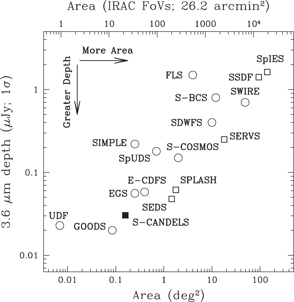
The authors are grateful to E. Diolaiti for helpful advice on the optimal use of StarFinder. This work is based on observations made with the Spitzer Space Telescope, which is operated by the Jet Propulsion Laboratory, California Institute of Technology under contract with the National Aeronautics and Space Administration (NASA). Support for this work was provided by NASA through contract numbers 1439337 and 1439801 issued by JPL/Caltech, and by HST grant GO-12060.05-A. J. S. D. acknowledges the support of the European Research Council via an Advanced Grant, and the support of the Royal Society via a Wolfson Research Merit Award. IRAF is distributed by the National Optical Astronomy Observatory, which is operated by the Association of Universities for Research in Astronomy (AURA) under cooperative agreement with the National Science Foundation.
Facilities: Spitzer Space Telescope - Spitzer Space Telescope satellite (IRAC)
Footnotes
- 7
Three AORs in the UDS field observed in 2012 March were useless because solar particles saturated the detectors. These AORs were reobserved in 2013 March. Recovery from a spacecraft anomaly in 2011 August prevented observation of 17 AORs in the EGS. They were observed in 2012 August.
- 8
The EGS dither pattern was equivalent to alternate positions of the medium Reuleaux 36 pattern and was specified via a cluster target.
- 9
- 10
- 11
Each mosaic pixel is one-fourth of an IRAC pixel, so the true noise is double the standard deviation measured in the mosaic. Surface brightness due to known sources was measured on the model mosaics, which by construction include the contributions of all detected sources and nothing else.