

Abstract
The silicon (Si) etching characteristics and the related efficiency of the etched Si to generate SiH4 gas in narrow-gap high-pressure microwave H2 plasma have been investigated. It was found that cooling of the Si sample is effective to obtain a high etching rate even under high pressure conditions, and the excess temperature increase of both the gas and Si sample can be suppressed even at an input power density of more than 250 W cm−3, probably because of the narrow plasma gap. The local etching depth monotonically increased with increasing H2 pressure and input plasma power, whereas the etching weight decreased with increasing H2 pressure. By simultaneously increasing the H2 pressure and input power, a maximum Si etching rate of 38 μm min−1 was achieved. This is considered to be related to the high H density generated in the narrow-gap microwave plasma at relatively low temperatures. The energy efficiency of Si etching and the utilization efficiency of the etched Si and H2 gas for SiH4 formation are discussed. Lower input power is favorable for high energy efficiency of Si etching. The Si utilization efficiency, which is defined as the molar ratio of generated SiH4 to etched Si, increases with decreasing average gas residence time in the plasma, whereas H2 utilization efficiency is independent of the gas residence time.
Export citation and abstract BibTeX RIS
1. Introduction
Silane is a very important material as a starting chemical for organosilicon synthesis [1] and to produce high-purity Si for electronic device applications [2–5]. In particular, in the conventional value chain of solar cell production, the refined Si material for solar cells, so-called solar grade silicon (SOG-Si), is mainly produced through a purification process using chlorine (Siemens method) and 99% pure metallurgical grade silicon (MG-Si) [6–8]. As the starting material, MG-Si is low-cost and abundant compared with SOG-Si, but its purification process accounts for the largest part (>65%) of the energy consumption in manufacturing c-Si cells [9]. One of the causes of the large energy consumption is the high temperature process required for chlorinated silane decomposition to effectively recover pure Si material. Furthermore, especially in the trichlorosilane process, the stoichiometric yield of purified Si from the input Si source is less than 50%. Thus, hydrogenated silane (SiH4), which has a lower decomposition temperature than chlorosilane, is very attractive from the viewpoint of reducing the thermal budget and achieving high Si yield. Furthermore, SiH4 is also often used for low-temperature preparation of thin Si films by plasma enhanced chemical vapor deposition. Because SiH4 gas is very toxic and flammable, and is supplied in the form of high-pressure gas charged in a heavy cylinder, additional equipment costs are necessary for its storage and daily use in addition to the deposition equipment costs. This is a barrier to investigation of Si film synthesis and application. Thus, it is better that only the required amount of silane is produced where and when it is needed from the viewpoint of both equipment cost and safety.
From the above background, we have attempted to develop a process to produce purified Si film from MG-Si based on a chemical transport phenomenon in high-pressure H2 plasma without using chlorine chemicals [10, 11]. When Si is immersed in H2 plasma, Si is etched according to the following reaction:

If the Si is MG-Si, the metal impurities remain in MG-Si during the reaction because most of the metal elements contained in MG-Si do not form hydrides or volatile hydrides [12]. Therefore, SiH4 gas can be generated from the Si material with elimination of most of the metal impurities that degrade solar cell efficiency [13]. Additional techniques are required to remove impurity atoms that form volatile hydrogen compounds (such as B and P). These gases can be separated using a specific property of each hydrogenated gas, such as the differences in decomposition temperature based on the thermal instability or adsorption behavior on a solid surface [11, 14]. In our system, the generation of silane gas is important to determine the throughput of the chemical-transport-based purification process from MG-Si to produce high purity Si films. In this study, we investigated the characteristics of Si etching and the utilization efficiency of the etched Si in narrow-gap high-pressure H2 plasma.
2. Experimental
Figure 1 shows a photograph of the generated narrow-gap H2 plasma (figure 1(a)), and the experimental apparatus used in this study (figure 1(b)). The electrode for plasma generation is a simple stainless steel (SS) pipe with an outer diameter of 1/8 inch-1/2 inch and a wall thickness of 1 mm. The plasma gap between the electrode and the Si sample can be adjusted from 0 mm to 5 mm by a screw-type electrode jig. H2 gas is supplied into the narrow plasma gap (0.6 mm) between the electrode and a Si solid source through the SS pipe with a flow rate (QH2) ranging from 5 standard liters per minute (SLM) to 27.5 SLM. As the Si solid source, a p-type (0 0 1) CZ-Si wafer with 1 Ω cm–50 Ω cm resistivity was set on the water-cooled stage. The H2 plasma was generated in the plasma gap by supplying microwave power of 2.45 GHz. The microwave was supplied to the pipe electrode with transverse electromagnetic mode. In a series of experiments, the H2 pressure (PH2) was varied in the range 5.3 kPa to 33.3 kPa (40 Torr to 250 Torr) and the input microwave power (Wμw) was varied from 100 W to 600 W. The Si etching rate was determined from the etched depth or the Si weight decrease divided by the etching time. The etching depth profile was measured by a stylus surface profiler (Surfcom 590A, Tokyo Seimitsu, Tokyo, Japan) and the Si weight decrease by an electronic balance. Because the high-pressure plasma was localized around the pipe electrode (as shown in figure 1(a)), the etching depth has a distribution along the radial direction of the pipe electrode – that is, the gas-flow direction. Therefore, in this study, the maximum etching depth was used as the etching depth. The depth etching rate (Rd, μm min−1) determined by the maximum etching depth was used to estimate the local hydrogen density. The weight etching rate (Rm, mg min−1) determined by the weight decrease of the Si sample is used to discuss the SiH4 generation rate. Optical emission spectroscopy was used to observe the radical emission from the H2 plasma. For this optical emission spectroscopy, a commercial optical spectrometer (USB2000, Ocean Optics, FL, USA) with a resolution of 1.5 nm was used without an external light collection optical system. The spectrometer entrance slit was 70 mm away from the plasma. To investigate the utilization efficiency of the etched Si, the volatile hydrogenated species generated by the interaction between H2 plasma and Si were analyzed by gas-phase Fourier-transform infrared absorption spectroscopy (FT-IR; FTIR-8600PC, Shimadzu, Kyoto, Japan).

Figure 1. (a) Photograph of the narrow-gap high-pressure H2 plasma and (b) schematic illustration of the H2 plasma reactor. The plasma in the photograph was generated by a 1/2-inch-diameter pipe electrode at H2 pressure of 13.3 kPa (100 Torr).
Download figure:
Standard image High-resolution image3. Results and discussion
3.1. Si etching properties by narrow-gap H2 plasma
First, to confirm the effect of cooling the Si sample on the etching rate, we conducted etching experiments with and without a water-cooled stage at Wμw = 100 W, PH2 = 8.0 kPa (60 Torr), and QH2 = 10 SLM. The Si temperatures measured by the thermocouple attached to the backside of the Si sample with and without the cooling stage were 50 °C and 350 °C, respectively. The actual Si surface temperature would be higher than these temperatures. The etching rates at 50 °C and 350 °C were 10.6 μm min−1 and 2.1 μm min−1, respectively. The etching rate at 50 °C was five times higher than that at 350 °C. This remarkable effect of cooling is consistent with previous results, which were characterized by a negative activation energy [14–18]. This tendency is characteristic behavior of the chemical etching reaction between Si and atomic hydrogen. Therefore, the Si etching phenomena observed in this study are not dominated by thermal evaporation owing to plasma heating but by chemical reaction, although the high input power is supplied to the small volume plasma. The temperature dependence of the negative activation energy has been explained by the presence of the reverse reaction to Si etching – namely, the heterogeneous recombination reaction of surface H atoms to release H2 molecules [15–17]. For this phenomenon, an effective substrate cooling system is indispensable to obtain high Si etching rates under constant input power. In the reaction studied here, atomic hydrogen impinging on the Si surface terminates unsaturated Si dangling bonds to form silicon hydride species (−SiH, −SiH2, and −SiH3) on the surface. In the case of a high flux of H atoms on the Si surface, breaking the Si bond between the substrate Si atom and the −SiH3 group can be induced by a H atom [19, 20]. Moreover, some of the H atoms reaching the Si surface abstract the hydrogen from the H-terminated Si surface by forming a H2 molecule, and some of the H atoms dissolve and diffuse into the Si bulk. By supplying a high flux of H atoms from plasma, a hydrogen-enriched layer is formed in the Si bulk near the surface, that is, in the subsurface region. Cleavage of Si bonds in the Si bulk crystal is induced by excess incorporated hydrogen and leads to platelet defect creation [21, 22]. This hydrogen-enriched layer near the Si surface seems to play an important role in generating SiH4 gas. The SiH4 formation process on the H-terminated Si surface has been reported to go through the following pathways [18, 23, 24]. (1) Reaction between H atoms and surface silyl (−SiH3) groups: H + −SiH3 → SiH4. (2) Reaction between the silyl group and the Si hydride group on the Si surface: −SiHx + −SiH3 → SiH4 + −SiHx−1 (x = 1, 2, or 3). Formation of the −SiH3 group on the Si surface is an important factor for Si etching. In pathway (1), it seems that not only H atoms existing in the plasma gas phase but also H atoms incorporated in the Si subsurface are important for SiH4 generation. Furthermore, it has been reported that the volatile SiHx (x ⩽ 3) radical is directly generated from the Si surface by atomic hydrogen etching [18, 24, 25]. However, the volatile SiHx (x ⩽ 3) radical has been observed in low hydrogen flux or high vacuum conditions. Moreover, the radicals have been observed at an elevated temperature of more than 300 °C [18, 24, 25]. However, in this study, hydrogen plasma etching is conducted in a high-pressure hydrogen atmosphere and at a low substrate temperature around room temperature. Therefore, Si etching seems to proceed mainly through the formation of SiH4 molecules, and SiHx radical generation in the Si etching process can be ignored, although SiHx radicals are generated by SiH4 decomposition in the plasma.
The Si etching phenomenon was not observed when pure He and Ar plasmas were generated instead of H2 plasma at WμW = 100 W and a total process pressure of 20 kPa. From this result, the Si etching reaction observed in this high-pressure atmosphere does not occur by physical sputtering because of high-energy ions in the plasma. The higher process pressure makes the mean free path of the particles shorter. In addition, the collision frequency among the particles becomes higher with increasing process pressure. For these reasons, because the ion energy given by the electric field could be rapidly dispersed on the neutral particles, the high-energy ions that can induce physical sputtering of Si are less likely to be generated in the high-pressure plasma. Therefore, the chemical reaction induced between H atoms and solid Si is the dominant factor in this Si etching process.
Figure 2 shows a typical emission spectrum of the H2 plasma during Si etching with PH2 = 5.3 kPa, Wμw = 600 W, and QH2 = 20 SLM. Strong emission lines from H atoms are present at 656 nm (Hα) and 486 nm (Hβ). Moreover, the Fulcher bands, which originate from excited H2 molecules [26], are present at around 600 nm. Emission bands around 414 nm from SiH radicals and an emission line at 288 nm from Si atoms are also present, which show that the SiH4 molecules generated by Si etching decompose in the H2 plasma. This re-decomposition in the plasma should be suppressed to obtain higher utilization efficiency of the etched Si.
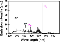
Figure 2. Optical emission spectrum during Si etching by high-pressure H2 plasma (PH2 = 5.3 kPa, Wμw = 600 W, QH2 = 20 SLM, 1/2 inch pipe electrode).
Download figure:
Standard image High-resolution imageFigure 3 shows that Rm (the weight etching rate) increases almost linearly with increasing Wμw (the input power). In figure 3, PH2 (the hydrogen pressure) and QH2 (the hydrogen flow rate) were 5.3 kPa and 20 SLM, respectively. The input power dependence of the Hα emission intensity obtained from the optical emission spectrum is also plotted in figure 3. The Hα intensity increases almost linearly with increasing Wμw, suggesting that the high etching rate may be related to the high H atom density in the present H2 plasma.

Figure 3. Si weight etching rate and Hα emission intensity as a function of input plasma power (PH2 = 5.3 kPa, QH2 = 20 SLM, 1/2 inch pipe electrode).
Download figure:
Standard image High-resolution imageFigure 4 shows Rd (the depth etching rate) and Rm as a function of H2 pressure (PH2) with Wμw = 100 W and QH2 = 10 SLM. Although Rd monotonically increases with PH2, Rm is almost independent of PH2. Under this serial experiment conditions, the optimum PH2 to obtain the maximum Rm is about 8.0 kPa. Furthermore, Rm gradually decreases with increasing PH2 above 8.0 kPa. This conflicting behavior between Rd and Rm with increasing PH2 seems to be mainly because of the variation of the plasma volume. Figure 5 shows surface profiles of etched Si obtained at PH2 = 5.3 kPa and 21.3 kPa, and the plasma appearance at each process pressure is also shown. As shown in this figure, the area of the etched Si surface and the bright region of the plasma clearly decrease with increasing PH2. This means that the plasma becomes more localized around the pipe electrode with increasing PH2. The power density of the plasma seems to increase with increasing PH2. Therefore, the maximum etching depth increases by the plasma localization effect.
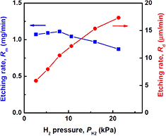
Figure 4. H2 pressure dependence of Si weight and depth etching rates by high-pressure H2 plasma (Wμw = 100 W, QH2 = 10 SLM, 1/4 inch pipe electrode).
Download figure:
Standard image High-resolution image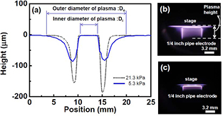
Figure 5. (a) Cross-sectional depth profiles of Si samples etched for 10 min at PH2 = 5.3 kPa and 21.3 kPa (Wμw = 100 W, QH2 = 10 SLM, 1/4 inch pipe electrode). Appearance of the plasma generated at (b) PH2 = 5.3 kPa and (c) 21.3 kPa.
Download figure:
Standard image High-resolution imageIn this experiment, the plasma volume at Wμw = 100 W was estimated to be at most 0.4 cm3 from the etching profile and plasma appearance observation. The plasma volume estimation was conducted by assuming that the plasma shape is a circular truncated cone with a hole in the middle of the basal plane as shown in figure 6. The height was determined by the plasma appearance (shown in figure 5(b)). The diameters of the basal plane and the hole were determined from the etching profile (shown in figure 5(a)). The power density of the plasma reached more than 250 W cm−3 at Wμw = 100 W. In high-pressure hydrogen plasma usually used to synthesize diamonds, it has been reported that the gas temperature easily exceeds more than 2000 K, even at input microwave power density of less than 30 W cm−3, and increases with increasing input power [27–30]. Considering this increase of gas temperature for the diamond synthesis plasma, the temperature of our Si sample surface may have greatly increased and the etching rate may not have increased because of the negative activation energy for the etching reaction despite the high atomic hydrogen density. However, as shown in figure 3, the etching rate almost linearly increased with increasing Wμw. This linear increase is considered to be because of the high flow rate of H2 gas and the narrow plasma gap. The narrow-gap plasma used in this study has a relatively large specific surface area compared with conventional diamond synthesis plasma. Therefore, the gas temperature is easily influenced by the boundaries, such as the water cooled electrode. This seems to be one of the characteristics of narrowing the plasma gap.
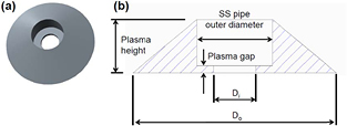
Figure 6. (a) The bird's eye view of the tridimensional model used for the estimation of plasma volume and (b) the cross-sectional diagram of the solid model. Each dimension is determined by the plasma appearance and the etching profile as shown in figure 5.
Download figure:
Standard image High-resolution imageAnd now, as shown in figure 4, in contrast to Rd, Rm gradually decreases with increasing PH2 above 8.0 kPa. This gradual decrease of Rm is considered to be because of the decrease of the plasma-exposure area and the increase of the gas residence time in the plasma reaction chamber. The Si temperature may also increase with increasing PH2, because the plasma gas temperature increases with increasing gas residence time at constant QH2. From this result, high PH2 is important to obtain a locally deeper etching profile and an optimum PH2 exists to obtain the highest throughput for SiH4 generation. The fact that the maximum etching depth increases with increasing PH2 means that the atomic hydrogen density at this local position can be increased by increasing PH2. According to the above results, a high local etching rate is expected by simultaneously increasing PH2 and Wμw. High-rate local etching of a Si sample was performed at PH2 = 33.3 kPa, Wμw = 500 W, and QH2 = 20 SLM. A maximum Rd of about 38 μm min−1 was achieved. Although the etching was localized near the pipe electrode, this etching rate is high and supposed to be related to the high H atom density generated by the narrow-gap high-pressure microwave H2 plasma [11, 31, 32]. The H atom density (nH) near the Si surface required to obtain a local etching rate of 38 μm min−1 was estimated by using the following equation:

where η,  , ΓSi, and nSi are the reaction probability, average velocity of hydrogen molecules, Si flux away from the sample surface, and Si atom density per unit volume, respectively. The reaction probability is defined as the contributing ratio of H atoms impinging on the Si surface for SiH4 gas formation. In other words, this reaction probability is the etching probability. Based on the literature, the etching probability of Si per H atom is of the order of 10−2 [17, 18, 33, 34]. Additionally, the average velocity of H2 molecules is assumed to be 3700 m s−1. Therefore, the estimated H density near the sample surface in the present experiment is of the order of 1016 cm−3. It should be noted that this value is not necessarily equal to the atomic hydrogen density in the plasma bulk. Because the process pressure of our plasma is high and the mean free path is less than a few micrometers, atomic hydrogen transport in the plasma is not only affected by the molecular flow but it is also strongly affected by diffusion. Thus, other measurement methods, such as actinometry [35] and laser absorption [36], should be used to confirm the atomic hydrogen density in the plasma bulk.
3.2. SiH4 yield and generation efficiency
In section 3.1, we confirmed that the local etching rate can be increased by simultaneously increasing PH2 and Wμw. However, from the viewpoint of using this system as an on-site silane generator, it is important to access not only the SiH4 generation rate but also the efficiency of the reaction system in terms of energy, Si consumption, and H2 usage.
First, the energy efficiency of Si etching, which is defined by the etching rate per unit input energy, was investigated. Figure 7 shows the input power dependence of the energy efficiency of etching. As shown in figure 7, the energy efficiency decreases with increasing Wμw. In figure 3, the weight etching rate (Rm) almost linearly increases with increasing Wμw, and their relationship can be represented as Rm = aWμw + b, where a is a constant and b is the y intercept obtained by linear extrapolation. The energy efficiency (Rm/Wμw) is then inversely proportional to Wμw such that Rm/Wμw = a + b/Wμw. This result suggests that the energy efficiency is the highest when Wμw is close to the plasma breakdown power. The reasons for this result are unclear because various plasma parameters, such as gas and electron temperatures and plasma density, can vary with increasing Wμw. Moreover, plasma volume expansion is also considered to be one of the reasons, because the plasma part away from the Si surface increases with volume expansion. From the above result, higher input power is a simple way to obtain a larger amount of etching. However, if we require high energy efficiency, it may be better to divide high-power plasma into a number of small-volume plasmas, namely low-power microplasmas. Moreover, the SiH4 partial pressure in the plasma will not continue to increase with increasing gas residence time but should saturate at an equilibrium SiH4 partial pressure because the deposition reaction, which is the back reaction of the SiH4 generation, becomes significant with increasing SiH4 partial pressure. Therefore, if a large-area plasma is generated that produces a long gas residence time, a part of the input power is used to maintain the plasma, which does not contribute to increasing the SiH4 concentration. This wasted energy is mainly caused by the excessive gas residence time in the plasma. Hence, using small-volume plasma seems to be one way to improve the energy efficiency of SiH4 generation.
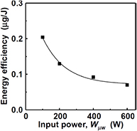
Figure 7. Si etching rate per unit energy (etching efficiency) as a function of input plasma power (PH2 = 5.3 kPa, QH2 = 20 SLM, 1/2 inch pipe electrode).
Download figure:
Standard image High-resolution imageNext, from the viewpoint of material usage, it is important to evaluate the Si utilization efficiency, which is defined as the ratio of the amount of SiH4 obtained to the amount of etched Si. Figure 8 shows a photograph of the Si surface etched with a relatively low H2 flow rate (QH2 = 5 SLM). In this image, Si particles cover the outside of the circular etched area, which appears dark brown to yellow on the Si surface. The circular etched area is almost coincident with the plasma area. The etched Si surface is mirror-like and almost free of Si particles. This result suggests that particle coarsening very rarely occurs in the narrow-gap hydrogen plasma because of the short residence time and hydrogen termination of Si dangling bonds, even if the nucleation of Si particles is occurred in the plasma. The amount of Si particles is high just outside the etched area (plasma area) and decreases further away from the plasma area. Particle formation outside the plasma may be related to the coarsening of fine particles because of the lack of termination of dangling bonds by atomic hydrogen. In the high-pressure atmosphere, the three-body recombination reaction of atomic hydrogen [37, 38] becomes too significant to ignore. Thus, atomic hydrogen recombines to form H2 molecules immediately after leaving the plasma. Because the sticking coefficient of the H2 molecule on the bare Si surface is very small [39], the dangling bond on the fine Si particle surface becomes hard to terminate outside the plasma. Therefore, it seems that the coarsening of the particle becomes significant outside the plasma. Moreover, the vortex gas flow around the pipe electrode and vacuum ultraviolet (VUV) radiation from the H2 plasma might also influence particle formation in this area. Because the hydrogen pressure of our plasma is high, a continuous VUV radiation spectrum, which induces photodissociation of SiH4 [40], may be observed – similar to deuterium lamp irradiation [41, 42]. From this typical photograph of the etched Si sample, it is confirmed that the etched Si transforms not only to SiH4 gas but also to solid Si particles by the plasma reaction, although the amount of generated particles depends on the experimental conditions.
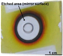
Figure 8. Photograph of the etched Si surface. Si particles accumulated around the etched area (PH2 = 8.0 kPa, Wμw = 400 W, QH2 = 5 SLM, 1/2 inch pipe electrode).
Download figure:
Standard image High-resolution imageTo determine the utilization efficiency of the etched Si as SiH4 gas, we measured the etched Si weight, the weight of generated Si particles, and the SiH4 concentration in the process atmosphere. Si particles on the Si surface were collected by the swab method and trapped by a fine mesh filter, which was installed in between the plasma chamber and the vacuum pump. The etching products in the gas phase were transported through 1 m-long gas tubing to a gas cell and analyzed by FT-IR spectroscopy. The gas cell had a 3 m optical path by multiple reflections. Figure 9 shows a typical FT-IR absorption spectrum of the etching product generated by the interaction of H2 plasma with Si wafer. The plasma was generated at PH2 = 5.3 kPa (40 Torr), Wμw = 100 W, QH2 = 10 SLM, and a plasma gap of 0.6 mm. As shown in figure 9, two predominant peaks are present at 913 cm−1 and 2189 cm−1, corresponding to the ν3 and ν4 bands of SiH4 [43, 44], respectively. In this spectrum, the ν6 band [45] of Si2H6 at around 843 cm−1 is not present. Hence, the density of stable higher order silane molecules, which can drift to 1 m downstream from the plasma, is below the determination limit of FT-IR spectroscopy and the main etching product is determined to be SiH4 gas. By changing the tube length from 1 m to 5 m it was also confirmed that the SiH4 concentration detected by FT-IR measurement was independent of the transportation distance. This means that the FT-IR absorption peak used to measure the SiH4 concentration is not influenced by the reactive hydrogenated silicon species SiHx (x = 1, 2, or 3). The SiH4 molar concentration was determined by the FT-IR absorption peak intensity of the 913 cm−1 peak using a calibration curve obtained by measuring commercial SiH4 gas with known concentration at the same total pressure as the plasma etching experiment. The commercial SiH4 and H2 were supplied to this in-line FT-IR system through each mass flow controller to adjust each mass flow rate. Furthermore, the total pressure in the FT-IR gas cell was also measured by the capacitance manometer attached to the cell. The relationship between the SiH4 mass flow rate and the infrared absorbance can be revealed by this calibration. The typical calibration curves obtained at the FTIR spectrometer resolution of 4 cm−1 are shown in figure 10. These curves are obtained at QH2 of 5 SLM and 10 SLM while keeping the total pressure of the plasma reactor at 8.0 kPa (60 Torr). This calibration should be done whenever there is a change in conductance of the exhaust system, FTIR spectrometer resolution, or the H2 flow rate. The measured absorbance does not necessarily increase linearly with increasing SiH4 mass flow rate – mainly due to the spectrometer resolution [46]. In the experiment for SiH4 generation, by measuring the absorbance at 913 cm−1, the SiH4 mass flow rate in the FT-IR gas cell can be estimated by comparing with the obtained calibration curve. Therefore, the SiH4 generation rate can be found in the form of mass flow rate. The utilization efficiency of the etched Si as SiH4 gas was determined from the amount of generated SiH4 and the amount of etched Si for an etching time of 10 min. We define the particle yield as the ratio of the particle weight to the etched Si weight. The particle weight includes all of the Si particles accumulated on the etched Si wafer and those trapped by the fine mesh filter. Figure 11 shows the etched Si weight and the weight of generated Si particles as a function of H2 flow rate (QH2). From figure 11, particle generation decreases with increasing QH2, while the etched Si weight increases with increasing QH2. The particle yield drastically decreases with increasing H2 flow rate and becomes less than 10% at QH2 = 20 SLM, which indicates that more than 90% of the etched Si is converted to SiH4 gas. From this result, it is suggested that the gas flow rate is an important factor to achieve high utilization efficiency of etched Si.
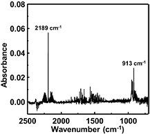
Figure 9. Typical FT-IR absorption spectrum during Si etching by high-pressure H2 plasma (PH2 = 5.3 kPa, Wμw = 100 W, QH2 = 10 SLM, 1/4 inch pipe electrode).
Download figure:
Standard image High-resolution image
Figure 10. Typical calibration curves to estimate the SiH4 generation rate. Green squares and blue triangles represent the relationships between SiH4 mass flow rate and the infrared absorbance at QH2 of 5 SLM and 10 SLM, respectively. These curves were obtained at the FTIR spectrometer resolution of 4 cm−1 while keeping total pressure at 8.0 kPa.
Download figure:
Standard image High-resolution image
Figure 11. Etched Si weight, particle weight, and particle yield after 10 min etching as a function of H2 flow rate (PH2 = 8.0 kPa, Wμw = 400 W, 1/2 inch pipe electrode).
Download figure:
Standard image High-resolution imageTo investigate the effects of the plasma area and the gas flow rate on the utilization efficiency, Si etching experiments were performed by changing the diameter of the SS pipe electrode. By varying the pipe diameter, the plasma area and the gas flow velocity simultaneously changed. Figure 12 shows the relationships between QH2 and Si etching rate (figure 12(a)) and QH2 and SiH4 generation rate (figure 12(b)) for three different diameter SS pipe electrodes. The data for the 1/2 inch pipe in figure 12(a) were obtained from the same data in figure 11 divided by the etching time of 10 min. To maintain a constant power density of the plasma, the input power Wμw was adjusted to be proportional to the electrode diameter. The wall thickness of three different outer-diameter pipe electrodes was constant at 1 mm. Therefore, the electrode area (Se) that directly faces the grounded substrate can be calculated as  (mm2), where D0 is the outer diameter of the electrode. Then, we chose the input power by assuming that the plasma is generated in a volume of
  , where dgap is the plasma gap. The etching rate increases with increasing QH2 for each pipe diameter, except for the 1/8 inch pipe at 20 SLM. Because the gas residence time in the plasma is the shortest for this plot, it has been suggested that a certain gas residence time is required to generate enough H atoms by plasma dissociation [47]. Figure 12(a) also shows that the Si etching rate increases with increasing pipe diameter. This tendency seems to be simply related to the increase of the plasma etching area. Figure 12(b) shows that the pipe diameter has little effect on the SiH4 generation rate, except for a 1/8 inch pipe at 20 SLM. To understand these tendencies of the effect of the pipe diameter, we analyzed the experimental data in terms of the average gas residence time (τ) in the plasma. In this study, τ was determined by the plasma length (dl) along the radial thickness direction of the SS pipe wall divided by the average gas velocity (v):

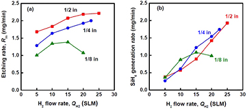
Figure 12. (a) Etching rate of Si and (b) SiH4 generation rate as a function of H2 flow rate for different diameters of SS pipe electrode (PH2 = 8.0 kPa, Wμw = 100 W for 1/8 inch, 200 W for 1/4 inch, and 400 W for 1/2 inch).
Download figure:
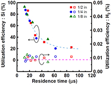
Standard image High-resolution imageHere, loc is the length of the outer circumference of the pipe, dgap is the plasma gap, and loc·dgap is the area through which H2 gas flows out. The unit of PH2 is kPa. dl was determined by the width of the etched area on the Si sample. Based on this assumption, the relationship between the utilization efficiency of the source materials and the average gas residence time (τ) is plotted in figure 13. The utilization efficiency of H2 gas is defined as the amount of H2 gas contributing to SiH4 formation divided by the amount of supplied H2 gas. As shown in figure 13, despite the use of different pipe diameters, the relationship between the utilization efficiency of the etched Si and τ can be well-described by a single curve. The utilization efficiency of the etched Si has a strong dependence on τ and greatly increases with decreasing τ, reaching >90% for τ < 13 μs. It was found that utilization efficiencies of >80% can be easily achieved by decreasing τ below about 15 μs. Conversely, the utilization efficiency of H2 gas shows little change with τ and is around 0.01%. All of the utilization efficiency trends seem to be related to the fact that, as previously mentioned, the SiH4 partial pressure in the plasma cannot continue to increase with increasing residence time because deposition on the Si substrate and particle formation become significant with increasing SiH4 partial pressure. Therefore, an equilibrium partial pressure of SiH4 gas at which deposition balances the etching phenomena would exist in this process. It seems that the following reactions proceed with τ along the gas-flow direction in the plasma. After the dissociation reaction of H2 molecules, SiH4 molecules form by the Si etching reaction with H atoms, and the SiH4 partial pressure increases and approaches an equilibrium pressure. In the case of long τ, some of the SiH4 molecules decompose in the plasma and reactive SiHx radicals are produced. Reactive radicals may condense and form higher order silane related species. As a result, Si re-deposition in the plasma and particle formation outside of plasma markedly increase with increasing τ. In particular, if the re-deposition process of generated SiH4 only occurs significantly when keeping the equilibrium SiH4 pressure constant, the utilization efficiencies of Si and H2 would not be affected. But the energy efficiency would decrease because the change of measured weight after Si etching due to this re-deposition process would not be counted as the etched Si weight. Conversely, if the formation processes of higher order silanes and Si particles occur significantly, the utilization efficiency of Si would markedly decrease without a significant decrease in the H2 utilization efficiency because the higher order silane generation process (i.e. clustering of Si atoms) in the plasma seems to act as a sink for generated SiH4. Thus, to keep the SiH4 equilibrium pressure constant in the plasma, Si etching will continue and the measured etched Si weight will increase. In this case, the SiH4 partial pressure is constant at the equilibrium pressure and the etched Si weight increases. Therefore, the SiH4 partial pressure is the same as the SiH4 concentration in H2 atmosphere. Thus, it seems that the utilization efficiency of H2 does not decrease, but Si utilization efficiency decreases with increasing τ.
Figure 13. Utilization efficiencies of the source materials as a function of gas residence time in plasma for different diameters of SS pipe electrode. Closed and open symbols correspond to Si and H2 utilization efficiency, respectively (PH2 = 8.0 kPa, Wμw = 100 W–400 W, QH2 = 5 SLM–27.5 SLM).
Download figure:
Standard image High-resolution image
The increase of τ is nearly equivalent to increasing the gas residence time in the reaction chamber. The gas residence time in the reaction chamber is solely determined by the total pressure and gas flow rate, and is independent of the plasma area. For example, the residence time in our chamber (125 cm3 volume) was about 117 ms when the hydrogen flow rate and total pressure were 5 SLM and 8.0 kPa (60 Torr), respectively. This residence time is more than 1000 times longer than τ in the plasma. During the residence time in the reaction chamber, generated SiH4 molecules might be decomposed by VUV irradiation and react with atomic hydrogen from the plasma. In the case of short τ, generated SiH4 molecules can leave the plasma before they decompose and the probability of particle formation decreases. The decrease of τ most often leads to a decrease of the residence time in the reaction chamber. Therefore, by also considering the residence time in the chamber, the utilization efficiency of etched Si may greatly increase with decreasing τ. If the input power density varied, the plasma parameters, such as electron temperature, electron density, and gas temperature, would change. Because these parameters are strongly correlated with the reaction rate induced in the plasma, the decay behavior of the utilization efficiency of etched Si would be influenced by changing the input power density.
As discussed above, it should be emphasized that the main factor to obtain high utilization efficiency of Si is not the H2 gas flow rate but the residence time in the plasma, because the utilization efficiency obtained with different electrode diameters cannot be uniquely plotted as a function of H2 flow rate but can be plotted as a unified curve as a function of the residence time in the chamber.
From the above results, it can be concluded that the gas residence time in the plasma should be short so H2 gas can be sufficiently decomposed to achieve high utilization efficiency of etched Si. The utilization efficiency of the H2 gas is constant at 0.01% and remains at a low level. Hence, in the chemical transport system to obtain a high purity Si film, the H2 gas should be recycled using a closed reaction system of circulation and regeneration. Improvement of the hydrogen utilization efficiency will be the subject of future work.
4. Summary
Toward efficient SiH4 production by direct hydrogenation of MG-Si for photovoltaic applications, the Si etching characteristics, utilization efficiencies of the source materials for SiH4 generation, and conversion behavior from solid Si to SiH4 in narrow-gap high-pressure microwave H2 plasma were investigated. For efficient Si etching, cooling of the Si sample is important. The narrow-gap plasma seems to be adequate for the Si etching application, because the excess increase of the gas temperature can be suppressed – even in the case of high microwave power density – to obtain high atomic hydrogen density. By simultaneously increasing the H2 pressure and the input power, a maximum Si etching rate of 38 μm min−1 was achieved. This etching rate indicates that the H density near the sample surface is at least of the order of 1016 cm−3. Although the etched Si weight per unit time increases with increasing input power, the input power density should be as low as the breakdown power for high energy efficiency in Si etching. The utilization efficiency of the etched Si increases with decreasing average gas residence time in the plasma. With increasing residence time, the probability of Si particle formation increases because of the decomposition of generated SiH4 molecules in the plasma. By decreasing the residence time below about 15 μs, high utilization efficiencies of the etched Si can be achieved (>80%). The utilization efficiency of H2 gas is almost constant at 0.01% and independent of the gas residence time in the plasma. This constant utilization efficiency of H2 gas seems to be because of the equilibrium partial pressure of SiH4 at which deposition balances etching. Improvement of the utilization efficiency of H2 gas will be investigated in future work.
Acknowledgments
This work was carried out in the Ultra Clean Room of the Department of Precision Science and Technology and in the Ultra Clean Facility of the Research Center for Ultra-precision Science and Technology, Osaka University. This work is partially supported by NEDO.